THE EFFECTS OF SURFACE TOPOGRAPHY AND LACK OF FUSION ON THE FATIGUE STRENGTH OF LASER HYBRID WELDS
Paper (101)
Md. Minhaj Alam1, Zuheir Barsoum2, Pär Jonsén1, Hans-Åke Häggblad1, Alexander Kaplan1
1
Luleå University of Technology (LTU), Dept. of Applied Physics and Mechanical Engineering SE 971 87, Luleå, Sweden
2
Royal Institute of Technology (KTH), Dept. of Aeronautical and Vehicle Engineering, SE 100 44, Stockholm, Sweden
Abstract
The geometrical aspects of laser hybrid welds (before, during and after the process) differ from autonomous laser welding and from arc welding. When studying the fatigue behaviour of laser hybrid welded fillet joints we identified that the micro-topography (i.e. the surface ripples) can be more important than the macrogeometry of the weld surface or lack of fusion (LOF), which frequently was detected. The plastic replica method was applied to measure the toe radii at the weld edges while the micro-topography was identified by interferometric profilometry. From metallurgical analysis of the joint interface, the tendency to LOF can be explained. Stress analysis was carried out by Finite element analysis (FEA) for the complex joint geometry and a bending load situation, showing maximum stress on the weld toes, even when including LOF. It was shown that the position and value of the maximum stress depends on a non-trivial combination of the weld geometry, including possible LOF, and the surface micro-topography. Thus it can be explained that at compressive stress conditions LOF does not contribute significantly to the fatigue strength of laser hybrid welds while the surface topography does. Recommendations for defining and in turn avoiding critical geometrical aspects during the welding process are discussed.
Introduction
Weld joints are characterized by differences in mechanical properties produced by geometrical, material and metallurgical discontinuities. As a consequence, fatigue failures appear in welded structures mostly at the welds rather than in the base metal. Crack-like defects on the weld surface (e.g. cold lap, surface ripples, notches and internal defects e.g. lack of fusion (LOF), lack of penetration (LOP)) are fatigue crack initiators, depending on the loading
condition [1-7]. Thus, a smooth weld surface geometry with minimal defects will optimise the fatigue strength of a welded joint. The welding process and its parameters influence the geometry of the weld. For example, the manual metal arc welding process tends to form a highly irregular weld toe, which leads to sharp transitions between the weld and the base metal. Unusual joint geometries, load situations and new welding techniques can produce new, complex situations from the point of view of fatigue behaviour. This paper studies laser hybrid welding of an eccentric fillet joint under a 4-point bending load. Hybrid welding [8, 9] combines a laser beam with an electric arc (MIG) and creates a narrow deep weld (from the laser beam) but also has the freedom to shape the surface (from the MIG parameters).
Models of fatigue behaviour usually estimate weld toe geometry by a weld angle, and a circular arc which defines the weld toe radius. This macro geometry affects the local stress concentration together with defects of different types. Also there is another important weld surface geometry - weld surface waviness or ripples i.e. micro geometry from where cracks initiate. Chapetti and Otegui [10] investigated the effect of toe irregularity for fatigue resistance of welds and concluded that the period of toe waves, as well as micro geometry, strongly influences fatigue crack initiation and propagation lives.
LOF is normally considered a very dangerous weld defect in a welded structure. Because of the notch effect, a crack may further propagate under the smallest load applied. The occurrence of the lack-of-fusion and its characteristic is described for gas shielded arc welding processes in [11]. The main cause for the occurrence of lack of fusion is insufficient energy input to the weld area. This means that the parent metal in the weld groove or previous runs have not heated to the melting point to make a uniform joint. This is mainly affected by the groove preparation, the welding technology and welding parameters chosen
[12]. Lack of fusion most often results from the weld pool running ahead of the arc. An important influence is exerted also by the welding parameters, i.e. welding current, voltage, welding speed, wire feed speed, and wire extension length. The torch inclination, welding position, weld preparation and arc deflection are important too [13]. In this paper, four point bend fatigue analysis was carried out on hybrid laser welded eccentric fillet joint. LOF was detected by microscopic analysis which was later used in a FE model including measured values of surface macro-geometry and micro-topography. LEFM analysis was carried out to calculate fatigue strength for different crack combinations.
Experimental Setup
The joint type studied involves two 10 mm thick steel plates in butt configuration, but with m = 5 mm eccentricity, see Fig. 1. This design was stipulated for a specific industrial application. Structural stainless steel SS2333 was used with sample dimensions of w x l x t = 50 x 100 x 10 mm3, prepared by milling and
grinding of the joint surface to give zero gap. Fillet welds were made between two base plates with 5 mm eccentricity using the hybrid laser metal inert gas (L/MIG) welding technique, see Fig. 1. The chemical composition and mechanical properties of the base metal and the filler wire are presented in Tables 1 and 2. After the welding had been completed, all specimens were milled to remove about 12.5 mm from both ends of the weld to remove start and stop defects. Consequently, a small square plate with 25 x 25 x 5 mm3 dimensions was attached by manual arc weld
under the eccentric base metal to facilitate sample attachment to the fatigue testing machine. The load condition was 4-point bending (see later), applying the force from the bottom. An Ytterbium Fiber Laser (IPG Laser YLR 15000) with a maximum power of 15 kW (wavelength 1070 nm), beam parameters product 10.4 mm·mrad delivered through a 200 µm fiber core, was in used for these experiments
.
The optics (focusing collimating length = 300:150 = 2:1) created a beam with a focal diameter of 400 µm and a Rayleigh length of ± 4 mm, with a focal plane position on the top surface of the weld. The laser was combined with a MIG-welding source (ESAB ARISTO). The filler wire, see Table 1, had a diameter of 1.2 mm. During the hybrid laser/MIG welding process, the laser beam was travelling 2 mm in front of the MIG torch. Further process parameters are summarized in Table 2. For statistical purposes 13 samples were welded under identical conditions. Figure 2 shows a typical top surface and weld cross section. The effective weld throat thickness is 6-7 mm and the leg length is 4 mm. As the bending force acts from the bottom, the weldroot shape is not important, as this area is under compressive stress. In contrast, the shape of the top of the weld was critical to the fatigue performance of these specimens.
The four point bend fatigue testing was performed using a servo- hydraulic machine (Instron 1272 max ± 50 kN). The welded joints were tested by keeping a constant amplitude stress ratio, R = 0 at a frequency of 45 Hz as shown in Fig. 3. The specimens were tested in the range from 2.5 kN to 4 kN until complete failure or to an endurance of 2 million cycles. A thicker beam than the base metal was specially prepared and hardened for fatigue testing with two different grooves so that the roller can fit the groove.
Fig. 1 Eccentric fillet joint
(a)
(b) (c) (d)
LOF
LOF
Fig. 2 Typical resulting weld: (a) weld top surface appearance, (b) defect-free weld cross section, (c) with lack of fusion-interface, (d) with distinct lack of fusion
Fig. 3 Four-point fatigue bending test (note: the weld is upside down)
Table 1: Chemical Composition (%) for the joints partners and filler wire
Material C Si Mn Cr Ni P S N SS2333 (sheets) .05 1.0 2.0 19 11 .045 .030 - Avesta 253MA (wire) .07 1.6 0.6 21 10 - - .15
Table 2: Hybrid welding parameters
Parameter Value/Type MIG current, high (constant) 328 A
MIG voltage, high (resulting) 27 V
MIG pulse time 2.4 ms
MIG frequency 90 Hz
Wire stick out length 16 mm
Wire feed rate 4.2 m/min
Shielding gas Ar
Shielding gas flow 20 l/min
Laser beam angle, α 10 °
Welding speed 1.05 m/min
Laser power 3.25 KW
Focal length (mm) 300
Magnification factor 2:1
Focal plane position 0
Impact of the macro-geometry
The surface macro-geometry is mainly determined by the toe radii and toe angles (see Fig. 1), and these were measured by the non-destructive plastic replica method [14, 15]. The measured data (radius and angle) were used to create a two-dimensional finite element (FE) model to calculate the stress concentration factor; Kt.
Figure 4 shows the relationship between all toe radii and toe angles. In this figure all the measured values from plastic replicas are plotted. Smooth toe radii and smaller toe angles give lower stress concentration factors [16]. Though many researchers have shown that toe radius is the most significant parameter for the stress concentration [17-19], out of our thirteen samples, only four specimens were cracked at the lower toe region whereas the rest of the specimens cracked within the weld bead, i.e. in the weld surface ripples. Therefore, the micro-topography (surface micro-geometry) of the welds was also studied. In order to calculate the stress fields and the stress concentration factors in the weld toes, stress analysis was carried out with the FEM using the ANSYS 11 software [20]. A linear elastic 2D model with the assumption of plane stress with thickness was applied, 25000 8-nodes quadrilateral elements were used, with mesh refinement around the toe regions. Residual stress was neglected due to the short weld length. According to the large scatter of the toe radii, Fig. 4, different radii-combinations were studied. Figure 5 shows stress field of smooth toe radii. Kt as a function
of the toe radius is plotted in Fig. 6. This figure shows how a smaller lower toe radius induces a much a higher stress peak than the upper toe, but for increasing radius this becomes less pronounced. Nevertheless, the lower toe has a shorter distance (throat) to the root and thus remains dominant. This indicates that the lower toe for eccentric filet joints in a four point bend situation is critical at the macro geometry level.
Fig. 4 Measured local weld geometry
Fig. 5 Calculated stress (1st principle in MPa) fields for a smooth surface for 1 mm lower and upper toe
Fig. 6 Stress concentration factor as a function of the upper and of the lower toe radius (Upper toe radius
kept constant at 1 mm)
Impact of the surface topography
A Wyko NT1100 was used for 3D optical profilometry. It utilizes vertical scanning/white light interferometry. A typical topography scan taken from the lower toe is shown in Fig. 7, showing the resolidification patterns which cover the surface. The measured data for three locations was extracted and imported into the FE code to compare with the ideal toe radius. Compared to the ideal toe radii, the stress peaks are considerably higher, see Figure 8. The present study aims to indicate the importance of stress raising resulting from features of the measured topography (compared to a smooth surface) for crack initiation. Once a crack is initiated, the stress level rapidly decays to the typical crack tip raiser values, thus the values of surface curvature and their stress peaks lose importance. Compared to the stress peaks from the toe radii, the welding ripples can cause significantly higher stress concentration. However, in the cases studied, the differences between the ripples were not so significant, therefore a ripple in the toe showed highest stress, as combined with the toe radius and neck impact. However low toe radii will shift the peak value to the most critical ripple in the weld bead.
Fig. 7 Typical measured weld surface topography at the lower toe radius; the ripples govern the surface curvature on a micro scale
(a)
(b)
(c)
Fig. 8: Stress (1st principle in MPa) fields calculated by FEA for a simplified cross section for the measured topography profile (a) case 1, (b) case 2, (c) case 3
Lack of Fusion
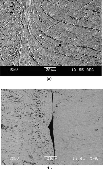
Lack of fusion (LOF) is a weld discontinuity in which fusion has not occurred between weld metal and parent metal or between adjoining weld beads. Microscopic analysis was carried out to detect LOF on all as-welded and fractured specimens. LOF was observed in most of the welded specimens. Joint surfaces were prepared by both sawing and milling, see Fig. 9. The two different surface preparations were not found to have any impact on the occurrence of LOF. After fatigue testing, the LOF surface was opened and examined. It was found that the parent metal surfaces were not fully melted in most cases, as demonstrated in Fig. 10 (b). The microstructure of a normal weld-parent metal interface is shown in figure 11, whereas figure 12
shows typical microstructures of LOF defects. The least detectable type of lack of fusion involves a sharp transition from one structure to another; see Fig. 12(a). This occurs when the molten metal contacts the parent metal but does not melt it. This is due to the presence of molten oxides on the surface of the melt. If, under the effect of internal stresses occurring during weld solidification and cooling, the two faces get separated, an open lack-of-fusion defect will be obtained. There is also LOF due to unmelted oxide inclusions, see Fig 12 (b), i.e. high melting point oxides or non-metallic inclusions are trapped between two adjoining faces. Oxides are arranged along the entire length of the LOF defect in a form of a thin layer. When they melt or slag occurs in the lack-of-fusion defect, globular non-metallic inclusions will form [5]. The oxide layer creates a thermal barrier between weld and parent metal which does not allow the parent metal to melt. By proper positioning of laser beam angle and adjusting welding speed, this effect can be minimized.
(a) (b)
Fig. 9 Joint edge surface prepared by (a) sawing, (b) milling
(a) (b)
Fig. 10 Surface after opening the lack of fusion: (a) weld bead side, (b) base metal side (milled
preparation)
Fig. 11 Weld cross section metallurgy: transition-HAZ
(a)
(b)
Fig. 12 Lack of fusion cross section: (a) contact, but limited melting transition, (b) distinct separation
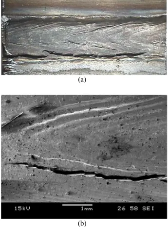
Fatigue Crack Geometry and discussion In this experiment, there were two different types of crack surfaces observed i.e. cracks in the weld toe and in the weld bead. Both cracks originated from undercuts according to Chapetti et al [21]. Surface ripples or waviness are here considered as undercuts. Figure 13(a) shows a typical cracked surface which failed at the lower toe. Multiple crack initiation can be expected for this kind of crack since some cracks follow surface ripples and others propagate parallel to the weld direction and join each other [22]. Figure 13(b) shows some of the crack initiation sites associated with local toe radius. These initiation sites correspond to positions in which the weld ripples approach the toe of the hybrid weld. In this situation the ripples follow the weld resolidification patterns. These defects are relatively long compared to their depth, and will cause a fairly constant stress concentration over most of their length. Figure 14 shows fatigue crack propagation from the lower and upper toes of welds with LOF defects. Experimentally it can be observed from Fig. 14 that LOF defects do not propagate, but they sometimes open as the weld fails. Linear elastic fracture mechanics analysis has been carried out with the help of LEFM code FRANC2D [23]. LOF (3 mm) defects were incorporated into the model with an initial crack length, ai= 0.1 mm where the upper and lower toe radii
was set 1 mm. The crack was allowed to propagate up to half of the weld throat thickness and it was found that the crack propagation direction was similar to the experiment without propagating LOF, see Fig. 15. While numerically calculating fatigue life from LEFM analysis, LOF with surface cracks slightly (<10%) reduces the fatigue life while LOF alone does not have any impact. Figure 16 shows a comparison of different crack situations on fatigue life with LOF and lower toe crack welded specimens with LOF have the lowest fatigue life. The weld top trace of the (longer) cracks of all 13 specimens is shown in Fig. 17. Many, but not all cracks follow the weld surface ripple pattern. Some cracks jump from an outer to an inner (with respect to the weld centre) ripple. Stress raising by the ripples obviously guides the cracks into a favoured direction, as forecast by the FE-simulation.
According to the present findings, an improvement of fatigue life by means of controlling the toe waviness is possible, e.g. controlling the weld pool flow as the origin of the ripples or by the post processing, e.g. surface remelting. Fatigue life improvement is also possible for this eccentric fillet joint by eliminating LOF which can be done with proper positioning of laser beam and optimizing welding speed.
(a)
(b)
Fig. 13 Typical crack geometry at the top surface; (a) cracking in the lower toe, partially propagating along
the weld ripples, (b) weld surface with crack propagating along the ripples
(a) (b) (c)
Fig. 14 Cross section of cracked welds (all with lack of fusion) after fatigue testing, with crack initiation (a) in the lower toe, (b) in the upper and lower toe, (c) in the
(a) (b) Fig. 15 Predicted fatigue crack propagation including 3
mm LOF; (a) initial condition (ai=0.1mm), (b)
fractured condition (af=3.5mm) 0 0.5 1 1.5 2 2.5 3 3.5 4
0.E+00 2.E+06 4.E+06 6.E+06 8.E+06 1.E+07
Cycles to failure C ra c k l e n g th (m m ) Upper toe Upper toe+LOF Low er toe Low er toe+LOF Weld bead Weld bead+LOF
Fig. 16 Fatigue life comparison for different crack situation
Fig. 17 Crack trace at the weld top surface for all 13 samples
Conclusion
• The lower toe radii are more critical than upper toe radii in this eccentric joint geometry.
• The toe radius does not always dominate the fatigue performance, as ripples can become local stress raisers.
• The surface ripples significantly raise stress. The ripples in the toe normally cause the highest stress except when the toe radius is large.
• The toe radius and surface topography can vary along the weld.
• Cracking follows the weld ripples at the weld surface.
• During fatigue, the LOF opened and top surface crack propagated in a curve manner while the root shows no crack. • LOF is not critical if under fully
compressive or at low tensile stresses load.
• LOF slightly (<10%) reduced fatigue life. • Three competing factors, namely the
throat distance, the toe radius and the ripple radii determine which region is most critical.
• Rules for laser hybrid welding of an eccentric fillet joint and for the process can be derived.
References
[1] Caccese, V., Blomquist, P.A., Berube, K.A., Webber, S.R., Orozco, N.J.(2006) Effect of weld geometric profile on fatigue life of cruciform welds made by laser/GMAW processes, Marine Structures 19, 1-22.
[2] Lee, C.H., Chang, K.H., Jang, G.C., Lee, C.Y. (2009) Effect of weld geometry on the fatigue life of non-load carrying fillet welded cruciform joints, Engineering Failure Analysis 16, 849-855.
[3] Nguyen, T.N., Wahab, M.A. (1995) A theoretical study of the effect of weld geometry parameters on
fatigue crack propagation life, Engineering Fracture Mechanics 51, 1-8.
[4] Wouters, M., Powell, J., Kaplan, A. (2006) The influence of joint gap on the strength of hybrid Nd:yttrium aluminum-garnet laser-metal inert gas welds, Journal of Laser Application 18, 181-184. [5] Rihar, G., Uran, M. (2006), Lack of Fusion- Characterisation of Indications, Welding in the World 50, 35-39.
[6] Singh, P.J., Achar, D. R. G., Guha, B., Nordberg, H. (2002) Influence of weld geometry and process on fatigue crack growth characteristics of AISI 304L cruciform joints containing lack of penetration defects, Science and Technology of Welding and Joining 7.
[7] Otegui, J.L., Kerr, H.W., Burns, D.J., Mohaupt, U.H. (1989) Fatigue crack initiation from defects at weld toes in Steel, International Journal of Pressure Vessels and Piping 38, 385-417
[8] Fatemi, A., Yang, L. (1998) Cumulative fatigue damage and life prediction theories: a survey of the state of the art for homogeneous materials, International Journal of Fatigue 20, 9-34.
[9] Yao, Y., Wouters, M., Powell, J., Nilsson, K., Kaplan, A. (2006) Influence of joint geometry and fit-up gaps on hybrid laser-metal active gas (MAG) welding, Journal of Laser Application 18, 283-288. [10] Chapetti, M.D., Otegui, J.L. (1995) Importance of toe irregularity for fatigue resistance of automatic welds, International Journal of Fatigue 17, 531-538. [11] Allen, D.J., Degnan, G. (1994) An Investigation of Fusion Quality in Conventional MIG, Synergic Pulsed MIG, Flux-Cored arc and Manual Metal Arc Welding, in Proceedings of the 2nd European Conference on Joining Technology, Eurojoin 2, Florence.
[12] Yamauchi, N., Inaba, Y., Taka, T. (1982) Formation Mechanisms of Lack of Fusion in MAG Welding, International Institute of Welding, IIW Doc. 212-529-82.
[13] Tusek, J., Blatnik, T. (2002) Ultrasonic Detection of Lack of Fusion in Spot Welds, Insight 44, 684-688. [14] Martinez, L. L. (1997) Fatigue behaviour of welded high-strength steels, Ph.D. thesis, Royal Institute of Technology, Sweden.
[15] Remes, H. (2007), Strain-based approach to fatigue strength assessment of laser-welded joints, Ph.D. thesis, Helsinki University of Technology, Finland.
[16] Ricondo, R.F. (2006) Fatigue and quality analysis of cruciform joints welded with different methods, Master’s thesis, Royal Institute of Technology, Sweden.
[17] Barsoum, Z. (2007) Residual Stress Analysis and fatigue assessment of welded steel structures, Ph.D. thesis, Royal Institute of Technology, Sweden.
[18] Martinsson, J. (2005), Fatigue Assessment of complex welded steel structures, Ph.D. thesis, Royal Institute of Technology, Sweden.
[19] Bell, R., Vosikovsky, O., Bain, S.A. (1989) Significance of weld toe undercuts in the fatigue of steel plate T-joints, International Journal of Fatigue 11, 3-11.
[20] ANSYS guide, ANSYS release 11. Houston : Swanson Analysis Systems.
[21] Chapetti, M.D., Otegui, J.L. (1997) Controlled toe waviness as a means to increase fatigue resistance of automatic welds in transverse loading, International Journal of Fatigue 19, 676-675.
[22] Alam, M.M., Barsoum, Z., Jonsén, P., Häggblad, H. A., Kaplan, A. (2009) Fatigue Behaviour Study Of Laser Hybrid Welded Eccentric Fillet Joints – Part I, in Proceedings of NOLAMP 12, Copenhagen, Denmark.
[23] FRANC2D. Version 3.2, www.cfg.cornell.edu Meet the authors
Md. Minhaj Alam was born in Rangpur, Bangladesh in 1981. He received his M.Sc. in Mechanical Engineering from Royal Institute of Technology, Stockholm, 2007, and has been working as PhD student at Luleå University of Technology, Luleå since 2007. His research area focuses on fatigue and fracture mechanics analysis of laser hybrid welded joint. Contact: minhaj.alam@ltu.se
Zuheir Barsoum received his doctoral degree in Lightweight Structures from The Royal Institute of Technology (KTH), dept of Aeronautical and Vehicle Engineering in 2008. Dr. Barsoum research interest is fatigue design and finite element analysis of engineering structures. Particularly fatigue design and testing of welded joints, weld quality, defect
assessment, applied fracture mechanics and welding residual stresses. Dr. Barsoum is also an expert member of the International institute of welding in commission XII which conduct research on the fatigue behaviour of welded structures and components. He is nowadays a faculty member at the dept of aeronautical and vehicle engineering at KTH. Contact: zuheir@kth.se.
Pär Jonsén was born in Kiruna, Sweden in 1971; receiving is doctoral degree in solid mechanics in 2006 from Luleå University of Technology, Department of Applied Physics and Mechanical Engineering. Research is focused on non-linear finite element simulation and particle based methods, modelling of powder processes and development of experimental methods. Main areas are development of material models, energy based crack models, damage in green bodies, crack energy measurements, fracture mechanics and studying of stress fields. Contact: par.jonsen@ltu.se.
Hans-Åke Häggblad was born in Örnsköldsvik, Sweden in 1955. Received his doctoral degree from Luleå University of Technology in 1993 on modeling and simulation of metal powder pressing. From 2004 and on he is appointed as professor at the division of solid mechanics at Luleå University of Technology. His main research interest is powder mechanics. Constitutive modelling and simulation of different powder based processes and granular materials. Moreover he is interested in modelling and simulation of different metal working processes and welding.Contact: hans-ake.haggblad@ltu.se.
Alexander Kaplan was born in Vienna, Austria in 1967, employed as researcher at Vienna TU from 1989 until 2000, receiving a PhD in 1994 on laser welding modelling. After a post-doc year at Osaka University, Japan, from 2002 on he is appointed as professor and head of division on manufacturing at Luleå University of Technology, Sweden. His research focus comprises laser materials processing, in particular process modelling, laser welding and hybrid welding. Contact: alexander.kaplan@ltu.se