New Concepts for Dielectrophoretic Separations
and Dielectric Measurements of Bioparticles
Fredrik Aldaeus
Licentiate Thesis in Chemistry KTH Chemical Science and Engineering
Analytical Chemistry Stockholm, Sweden, 2006
AKADEMISK AVHANDLING
som med tillstånd av Kungl Tekniska högskolan i Stockholm framlägges till offentlig granskning för avläggande av teknologie licentiatexamen i kemi måndag 27 mars 2006, kl. 10.15–11.15 i sal K2, Teknikringen 28, Stockholm.
New Concepts for Dielectrophoretic Separations and Dielectric Measurements of Bioparticles Fredrik Aldaeus
Thesis for the degree of Licentiate of Technology in Chemistry KTH Chemical Science and Engineering
Analytical Chemistry Stockholm, Sweden, 2006 ISBN 91-7178-286-9
Copyright © 2006, Fredrik Aldaeus
All rights reserved for the summary part of this thesis, including all pictures and figures. No part of this publication may be reproduced or transmitted in any form or by any means, without prior permission in writing from the copyright holder. The copyrights for the appended journal papers belong to the publishing houses of the journals concerned.
Denna avhandling beskriver genom beräkningsexemel två nya metoder för separation av mik-ropartiklar med hjälp av dielektrofores, nya beräkningar på dielektroforetisk rörelse i koncent-rerade suspensioner, och nya experimentella metoder för att erhålla riktigare värden på levande cellers dielektriska parametrar. Avhandlingen är baserad på fyra uppsatser.
Uppsats I beskriver hur superponerade elektriska fält signifikant kan förbättra infångning av mik-ropartiklar i suspensionsmedia med hög konduktivitet. Detta är viktigt eftersom det ofta är nöd-vändigt att undvika allt för låga konduktiviteter när levande celler används. Beräkningar utfördes för att beräkna partikelbanor för Escherichia coli-bakterier i system med superponerade elektriska fält, och en modell utvecklades med flera rader av parallella elektroder i en mikrokanal.
Uppsats II lägger fram en ny metod för separation av mikropartikar baserad på upprepat dielekt-roforetiskt infångande och frisläppande i ett flödessystem. Beräkningar visade att upplösningen var direkt proportionell mot antalet steg med infångande och frisläppande, och att skillnader i storlek påverkade separationen mer än skillnader i dielektroforetiska egenskaper. Polystyrenkulor i avjonat vatten användes som modell, och beräkningar utfördes för att prediktera separationsef-fektiviteten. Partiklar med en storleksskillnad på 0,2 % bör kunna separeras med 200 separa-tionssteg. Den förbättrade effektiviteten som erhålls med en dielektroforetisk separation med fle-ra steg kan ha viktiga tillämpningar, inte bafle-ra för ffle-raktionering av partiklar med liten skillnad i storlek, utan även för att mäta förändringar i ytkonduktivitet.
Uppsats III presenterar en ny beräkningsmetod för att förutsäga mikropartiklars dielektrofore-tiska rörelser. Metoden baserades på en metod från molekylärdynamik med mjuka sfärer. Beräk-ningsresultaten stämde väl överens med såväl teoretiska förutsägelser som praktiska experiment, vilket innebär att metoden gav god effektivitet och noggrannhet.
Uppsats IV beskriver en ny metod för att mäta konduktiviteten på levande bakterier. För att er-hålla pålitliga konduktivitetsvärden är det viktigt att behandla bakterierna så skonsamt som möj-ligt under mätprocessen. En standard-konduktivitetsmätare användes tillsammans med tvärflö-desfiltrering. På detta sätt kunde för bakterierna skadliga upprepade centrifugeringar och omsus-penderingar undvikas. Med hjälp av tvärflödesfiltrering kunde konduktiviteten på Bacillus subtilis bestämmas till 7000 µS/cm, vilket skiljer sig från tidigare publicerade värden med nästan en fak-tor tio.
Utöver det arbete som presenteras i uppsatserna har experiment på chip-baserade system utförts. Beteendet hos Escherichia coli (E. coli) och polystyrenkulor vid olika spänningar och frekvenser studerades. På en rad med parallella elektroder separerades kulor med olika storlek. Med spetsiga elektroder var det möjligt att observera hur E. coli radade upp sig i olika riktningar, bildade pärl-band, roterade, och utförde andra dielektroforetiskt inducerade rörelser.
Fredrik Aldaeus Stockholm, februari 2006
This thesis presents two new concepts for separation of micro particles using dielectrophoresis, demonstrated by calculated examples, as well as a new method for obtaining dielectric data on living cells. The thesis is based on four papers.
Paper I describes how the trapping efficiency of micro particles may be significantly increased when superpositioned electric fields are employed in a high conductivity medium. Avoiding low conductivity media is important when working with living cells. Calculations were performed to predict trajectories of Escherichia coli bacteria in the system with superpositioned electric fields, and a model was developed which employed two arrays of interdigitated electrodes in a micro channel.
Paper II proposes a new concept for separation of micro particles, based on repetitive dielectro-phoretic trapping and release in a flow system. Calculations show that the resolution increases as a direct function of the number of trap and release steps, and that a difference in size will have a larger influence on the separation than a difference in dielectrophoretic properties. Polystyrene beads in deionized water were used as a model, and calculations were performed to predict the particle behavior and the separation efficiency. It should be possible to separate particles with a size difference of 0.2 % by performing 200 trap-and-release steps. The enhanced separation po-wer of multi step dielectrophoresis could have significant applications, not only for fractionation of particles with small differences in size, but also for measuring changes in surface conductivity. Paper III presents a new calculation method for predicting dielectrophoretic motion of micro particles. The method is based on a soft sphere method often used in molecular dynamics. Re-sults from the calculations are in good agreement with theoretical predictions as well as initial ex-perimental results, showing that the method provides good efficiency and accuracy.
Paper IV describes a new method for measurements of conductivity of living bacteria. To obtain reliable conductivity values, it is important to handle the cells as gently as possible during the measurement process. A standard conductivity meter was used in combination with cross-flow filtration. In this way, repeated centrifugation and resuspension is avoided which otherwise may cause damage to the bacteria. The conductivity of Bacillus subtilis was determined to be 7000 µS/cm by means of the cross-flow filtration method, and the values differ from earlier published values by almost an order of a magnitude.
In addition to the work presented in the papers, some experimental dielectrophoresis work in chip-based systems was performed. The behavior of Escherichia coli and polystyrene beads at dif-ferent voltages and frequencies were studied. Separation of beads with difdif-ferent sizes was achieved on an array of interdigitated electrodes. Using electrodes with a pointed shape, align-ment in different directions, pearl-chain formation, rotation, and other dielectrophoretic motion of E. coli were observed.
Fredrik Aldaeus Stockholm, February 2006
Introduction... 5 Dielectrophoretic motion... 7 The superpositioned dielectrophoresis concept ... 9
Trapping in high conductivity media | Superpositioning of electric fields | Enhanced trapping The multi-step dielectrophoresis concept ... 12
Improving dielectrophoretic separations | Dielectrophoretic resolution and selectivity Enhanced separation power
Calculation methods ... 15 Model particles | Model chamber | Calculation procedure | Concentrated suspensions
The cross-flow filtration method for conductivity measurements... 18 Gentle pre-handling of cells | Isoconductance point | Preparation of B. Subtilis
Conductivity measurment device | Conductivity of gently treated cells
Dielectrophoresis experiments ... 20 Preparation of beads and bacteria | Open dielectrophoresis device
Positioning and separation of beads | Behavior of E. coli
Conclusions and future outlook ... 23 Acknowledgements ... 24 References ... 25 Appendicies
List of papers
This thesis is based on the following papers, referred to by their Roman numerals: I. »Superpositioned dielectrophoresis for enhanced trapping efficiency« Fredrik Aldaeus, Yuan Lin, Johan Roeraade, Gustav Amberg
Electrophoresis 26 (2005), 4252–4259
Reprinted with permission from Wiley-VHC Verlag GmbH & Co. (Copyright © 2006)
II. »Multi-stepped dielectrophoresis for separation of particles« Fredrik Aldaeus, Yuan Lin, Johan Roeraade, Gustav Amberg Submitted to Journal of Chromatography A (2006)
Reprinted with permission from Elsevier
III. »Simulation of dielectrophoretic motion of microparticles using a molecular dynamics approach«
Yuan Lin, Fredrik Aldaeus, Gustav Amberg, Johan Roeraade
Submitted to Proceedings of ASME ICNMM 2006 – 4th International Conference on Nanochannels, Microchannels and Minichannels (2006),
Limerick, Ireland, June 19–21, 2006 Reprinted with permission from ASME
IV. »Determination of conductivity of bacteria by using cross-flow filtration«
LarsErik Johansson, Fredrik Aldaeus, Gunnar Jonsson, Sven Hamp, Johan Roeraade Biotechnology Letters (2006), in press
Reprinted with permission from Springer Science+Business Media B.V. (Copyright © 2006)
The contributions of the author of this thesis to these papers are: I, II Major part of the writing, part of the calculations III Minor part of the writing and the experiments
Part of the work in this thesis has also been presented at conferences:
• »A study of biological particles in a bio-MEMS device using dielectrophoresis« Mats Jönsson, Fredrik Aldaeus, Lars-Erik Johansson, Ulf Lindberg,
Johan Roeraade, Ylva Bäcklund, Sven Hamp, Gunnar Jonsson Lecture and paper in the proceedings at Micro Systems Workshop ’04, Ystad, Sweden, March 30–21, 2004
• »Numerical predictions of continuous separations in a microfluidic positive dielectophoresis system«
Fredrik Aldaeus, Lin Yuan, Johan Roeraade, Gustav Amberg Poster at 4th Workshop on Nanochemistry and Nanobiotechnology, Saltsjöbaden, Sweden, August 25–27, 2004
• »Escherichia coli behavior in an open dielectrophoretic microsystem« Fredrik Aldaeus, Lars-Erik Johansson, Mats Jönsson, Gunnar Jonsson, Ulf Lindberg, Johan Roeraade, Sven Hamp
Poster at 4th Workshop on Nanochemistry and Nanobiotechnology, Saltsjöbaden, Sweden, August 25–27, 2004
• »Dielectrophoresis of living cells – new concepts and challenges« Fredrik Aldaeus, Lin Yuan, Mats Jönsson, Lars-Erik Johansson, Gunnar Jonsson, Johan Roeraade, Gustav Amberg
Lecture at 5th Workshop on Nanochemistry and Nanobiotechnology, Funchal, Madeira, Portugal, November 14–18, 2005
List of abbreviations
2D two-dimensional
3D three-dimensional
αDEP dielectrophoretic selectivity
δ phase shift ∇ del operator 2 ∇ Laplacian operator DEP ϑ dielectrophoretic mobility φ electric potential κ~ effective polarisability ω angular frequency A550 absorbance at 550 nm AC alternating current
B. subtilis Bacillus subtilis
DC direct current
DEP dielectrophoresis E electric field
E. coli Escherichia coli
F force
FDEP dielectrophoretic force
FFF field flow fractionation
MD molecular dynamics
OD600 Optical density at 600 nm
p induced dipole moment PDMS polydimethylsiloxane
q charge
R2 coefficient of determination
RDEP dielectrophoretic resolution
t time
uf velocity of the suspension medium
unDEP velocity induced by negative dielectrophoresis
upDEP velocity induced by positive dielectrophoresis
utot total velocity
Introduction
Separation of micro particles such as bacteria, yeast cells or polymer beads with different pro-perties is of great importance in modern mate-rial technology and life science. The rapid deve-lopment during the last decade of chip-based micro systems has had a tremendous impact on the field [1–3]. Chip-based systems have several features compared to macroscopic systems. A great advantage is that the size of biological cells or micro particles is in the same order of magnitude as the internal dimensions of a mic-ro-chip system. This enables work with a few or even single cells, and allows the design of very sensitive analytical methods. Many different forces may be employed to manipulate particles in a chip, for instance mechanical forces, mag-netic forces or optical forces. Electric forces are particularly well suited for miniaturization, be-cause a high field strength may easily be genera-ted with low voltages. Using electric forces, flu-id motion can be induced with electro-osmosis, while charged particles can be transported by electrophoresis, and polarisable particles may be manipulated with dielectrophoresis. Electric forces also provide the possibility to study both surface modifications and bulk properties [4– 5]. This is useful when studying for instance ef-fects of drugs on cells, efef-fects of external stimuli on cell behavior or in cancer diagnostics [6].
Two commonly used methods for particle separation are flow cytometry and field flow fractionation. Bench top flow cytometers are fast and powerful but expensive. Normally, the separation requires labeling with for instance fluorescent or magnetic markers [7]. This may affect some of the critical properties of the par-ticles such as viability and function, and it is difficult to downsize the equipment without lo-sing performance. Recently, a chip-based and label-free technology has been described, where the dielectric properties, measured by impe-dance spectroscopy, serve as a size and or/pro-perty indicator prior to flow cytometry [8]. However, the resolution of this system in terms of size difference is moderate.
Field flow fractionation (FFF) does not re-quire labeling [9]. The principle of this separa-tion technique is based on differences in hydro-dynamic behavior, where the particles position themselves in different regions of a laminar fluid stream. Usually, a perpendicular force, in the form of a gravitational, thermal, electric or dielectrophoretic field [10–11] is included to improve the separation. However, the separa-tion power, obtained in practice is modest and there is a great need for improved resolution.
As previously mentioned, dielectrophoresis is well suited for manipulation of particles in chip-based systems. Dielectrophoresis may be defined as »Motion of polarisable particles in spatially non-uniform electric fields« and was first described by Pohl in the early 1950’s [12]. Strong non-uniformity in electric fields was ini-tially difficult to obtain, but the improvements in micro fabrication where devices incorporate both micro electrodes and micro channels has lead to a widespread use of the method. The di-electrophoretic force is strongest close to the electrode edges, and acts on particles that are permanent dipoles or are polarisable. The di-rection of force depends on the polarisability of the particles and the surrounding medium.
Usually, dielectrophoretic separation devices are employed as trap-and-release-filters or par-ticle sorters. Different methods for trapping and sorting particles with dielectrophoresis have been described in the literature [4–5, 13], either with the purpose to direct one kind of particle to different positions, or to separate particle populations with significant difference in size and polarisability. Many types of partic-les can be separated, for instance different mic-ro-organisms or beads with different surface modifications. Separation by means of dielect-rophoresis does not necessarily rely on differen-ces in size or surface properties. Also the bulk properties of the particle may be crucial. An example of such a case is separation of viable and non viable cells [14–15], where the cells may be of similar size and outer appearance.
When handling living cells, trapping prob-lems may occur because the cells normally re-quire a surrounding matrix with at least a mo-derate conductivity [16–17]. With a high con-ductivity medium, the attracting dielectropho-retic motion may become low or even comple-tely absent [18]. This problem may be solved by diluting the suspension medium, but many cells are sensitive to conductivity changes. If viable cells are required for downstream use, it is of great importance to avoid exposing the cells to an environment of too low conductivi-ty.
This thesis describes two new concepts that may be used to increase the trapping and the separation efficiency in dielectrophoretic sepa-rations. In the first concept, two or more com-bined electric fields are utilized [Paper I]. The
second concept is based on a repetitive dielec-trophoretic trap- and-release [Paper II]. The calculations demonstrating these concepts were performed using Escherichia coli (E. coli) and polystyrene beads as model particles. These ma-terials were chosen in view of the major impor-tance of these micro-organisms and particles in biotechnology [19]. The calculations also in-clude some initial predictions on the behavior of concentrated particle suspensions [Paper III].
Tentative experimental dielectrophoresis work has been performed using the same mate-rials as in Paper I and Paper II (i.e. E. coli and polystyrene beads). The experimental work also includes a new, more reliable method for mea-suring the conductivity of living cells [Paper IV].
Dielectrophoretic motion
If a charged particle is placed in an electric field, the particle will be affected by a force pro-portional to the electric charge in the direction of the field (Figure 1A). Thus, if the charge is q and the field is E, the force is
F =qE (1)
If a particle with no net charge, but with the ability to become polarized is placed in an electric field between two electrodes, the char-ges in the particle are displaced in the direction towards the electrode with the opposite sign. Thus, the particle will be affected by a force in both directions. Since these two forces are equal in magnitude but have opposite direc-tions, there will be no net movement (Figure 1B). However, if the particle is placed in an electric field that is not uniform, the particle will be affected by a net force in the direction towards the higher field strength (Figure 1C). This is the phenomenon called dielectropho-resis [12]. The net dielectrophoretic force FDEP
is proportional to the polarisability of the par-ticle and the inhomogenity of the electric field.
(
p)
EFDEP = ⋅∇ (2)
where E is the electric field, ∇is the del opera-tor (
(
∂ ∂x,∂ ∂y)
in two dimensions), and p is the induced dipole moment.Particles in chemical applications are often suspended in a liquid medium. If the medium is polarizable and the force on the medium is larger than the force acting on the particle, the particle will be displaced in the direction to-wards the lower field strength. This motion is called negative dielectrophoresis. Positive di-electrophoresis will occur when the force on the particle is higher than the force on the medi-um, and the particle is moving in the direction towards higher field strength.
The induced dipole moment depends on the effective polarisability (κ~ ), the volume (V) of
A
B
C
Figure 1. A charged particle in a uniform
electric field (A) will experience a net force in the direction of the field, while a particle with no net charge (B) experiences no net force. A particle with no net charge but the ability to become polarized will experience a net force towards higher field strength when placed in a non-uniform electric field (C).
the particle, and the electric field:
The effective polarisability (κ~) can be calcu-lated from the shape of the particle and the di-electric properties (the conductivity and the permittivity) of the particle and the surroun-ding medium. The larger the volume of the particle, the larger the dipole moment will be-come since the charges may be more separated, whereas the magnitude of the electric field de-termines how much the charges are displaced. If Equation 2 and Equation 3 are combined, it can be seen that the dielectric force is propor-tional to the square of the electric field:
2 DEP 2 ~ E F =κV ∇ (4)
SinceE2 = −E2, the sign of the field has no influence. Thus, if the direction of the field is reversed, the movement will still be in the same direction. As a consequence, it is possible to use an alternating current (AC) electric field in-stead of a direct current (DC) electric field. A benefit of this is that the effective polarisability is dependent of the frequency of the applied field. For low frequencies, the effective polarisa-bility will be positive if the conductivity of the particle is larger than the conductivity of the medium, and negative if the conductivity of the medium is larger than the conductivity of the
particle. Hence, it is possible to have a move-ment in the direction towards either higher or lower field. A positive effective polarisability will result in positive dielectrophoresis, whereas a negative effective polarisability will result in negative dielectrophoresis. For high frequen-cies, the same line of reasoning may followed, but with permittivity instead of conductivity.
In most cases, it is of interest to know the ve-locity of a particle, rather than to just know the dielectrophoretic force. The velocity induced by dielectrophoretic motion can be written [20] as
2 DEP
DEP E
u =ϑ ∇ (5)
where ϑDEPis the dielectrophoretic mobility. It
is impossible to separate particles using dielect-rophoresis if not at least one of the parameters affecting the mobility (the permittivity, the conductivity, the size and the shape of the par-ticles, the permittivity, the conductivity and the viscosity of the medium, as well as the frequen-cy of the applied AC electric field) is different between the two sets of species. In the subse-quent calculations, the possibilities of exploi-ting differences in these parameters for separa-tion purposes are explored.
The superpositioned dielectrophoresis concept
Trapping in high conductivity media
Fractionation of cells is an issue of central im-portance in biotechnology. Often, the issue of maintaining viability may be unimportant, but for work where micro-organisms are used as templates for fermentation cultures, survival of the cells is of central importance. One method for maintaining viability is to avoid osmotic stress on the living cells by keeping the conduc-tivity of the suspension medium in the same range as the conductivity of the cells. This will cause problems since the effective polarisability becomes low and trapping will become diffi-cult. The effective polarisability will, as pre-viously mentioned, affect the mobility. As can be seen from the diagram in Figure 5A, the positive mobility decreases rapidly when the conductivity of the medium is increased, and will eventually become zero. Combined with the fact that the dielectric force only affects par-ticles at a small distance from the electrodes, trapping in high conductivity media is not fea-sible. However, under these conditions, the maximum negative mobility (at another AC frequency than for positive dielectrophoresis) is still high.
Superpositioning of electric fields
In the new concept, two AC electric fields with different frequencies are exerting a force on a system of particles suspended in a medium (Fi-gure 2). The fields must be considered as super-positioned [21–22], and if the difference bet-ween the AC frequencies is sufficiently large (i.e. several orders of magnitude), one of the fields induces positive dielectrophoresis, while the other field induces a negative dielectropho-resis [Box 1]. If uf is the velocity of the
suspen-sion medium, and upDEP and unDEP are the
respec-tive velocities induced by the posirespec-tive and the negative dielectrophoresis, the total velocity of the particle can be expressed as
nDEP pDEP
f
tot u u u
u = + + (6)
If the fields are opposing each other in a flow
Figure 2. Comparison of a case where one
and two sets of electrodes are used in a high conductivity medium.
A) Only attracting electrodes at the bottom of
the channel. The particles in the upper half pass the system without being trapped.
B) Attracting electrodes at both the top and
the bottom of the channel. The trapping efficiency is increased, but due to the weak dielectrophoretic force at high conductivities, the particles in the middle of the channel escape.
C) The top electrodes are given a repelling AC
frequency. At high conductivities, the re-pelling dielectrophoretic force is larger than the attracting force. This results in the par-ticles being pushed towards the attracting electrodes at the bottom of the channel. All particles are trapped (see also Paper I).
Reprinted with kind permission from Wiley-VHC Verlag GmbH & Co (Copyright © 2006)
channel, it is thus possible to push the particles from one set of electrodes closer to a set of trap-ping electrodes [Paper I].
Enhanced trapping
To investigate the feasibility to enhance the trapping efficiency using the suggested super-positioned dielectrophoresis, calculations on
particle trajectories in a micro system were per-formed. The trapping was assumed to take place in a flow conduit with the top and the bottom area patterned with micro electrodes arranged as an interdigitated array [23–26]. The particles were assumed to be trapped if the end point of a trajectory is at an electrode edge. The height of the channel used in this model is approximately 50 times larger than the diame-ter of the model particle E. coli.
As shown in Figure 2c, it is possible to in-crease the trapping efficiency in media with
high conductivity by using a row of electrodes on the top of the channel that is pushing the particles into a region closer to the attracting electrodes on the bottom of the channel. The reason is that for higher conductivities, the re-pelling force of negative dielectrophoresis is stronger than the attractive force of positive di-electrophoresis. For low conductivity media, attracting forces are stronger than repelling for-ces, and therefore, in that case, using two at-tracting arrays would be the preferred choice.
Box 1. The reason why two superpositioned alternating current electric fields can be useful in dielectrophoresis
The dielectrophoretic force and mobility are proportional to the gradient of the squared electric field (Equation 5). For the two-dimensional case, with
E = –∇ φ (B1.1)
where φ is the electric potential, the gradient of the squared electric field could for the 2D case be described (assuming that the electric field is free from rotation) as
⎟⎟ ⎠ ⎞ ⎜⎜ ⎝ ⎛ ∂ ∂ ∂ ∂ + ∂ ∂ ∂ ∂ ∂ ∂ ∂ ∂ ∂ ∂ + ∂ ∂ ∂ ∂ = ∇ 2 2 2 2 2 2 2 , 2 y y x y x y x y x x φ φ φ φ φ φ φ φ E (B1.2)
The total potentialφfrom the two fields may be written as
φ =φ1sin(ω1t)+φ2sin(ω2t+δ) (B1.3)
where φ1 and φ2 are the amplitudes of the two fields,ωis the angular frequency, t is the
time, and δ is the phase shift. Since the dielectrophoretic force is proportional to∇∇φ2, and the potential is induced by two fields with different frequencies, the total force is proportional to (( ) sin ( )) (( ) sin ( )) )) sin( ) sin( ( ) ( 2 2 2 2 1 2 2 1 2 2 2 1 1 2 δ ω φ ω φ δ ω φ ω φ φ + ∇ ∇ + ∇ ∇ = = + ∇ + ∇ ∇ = ∇ ∇ t t t t (B1.4)
To obtain the time averaged force, the squared electric field 2 )
(∇φ is integrated from time zero to a time T and then multiplied with 1/T.
1 2 c 0 2 ) ( 1 I I I dt T T + + = ∇ ∇
∫
φ (B1.5) where ⎟⎟ ⎠ ⎞ ⎜⎜ ⎝ ⎛ ∇ ∇ =∫
T t dt T I 0 1 2 2 1 1 sin ( ) 1 ) ( φ ω (B1.6) ⎟⎟ ⎠ ⎞ ⎜⎜ ⎝ ⎛ + ∇ ∇ =∫
T dt t T I 0 2 2 2 2 2 sin ( ) 1 ) ( φ ω δ (B1.7) ⎟⎟ ⎠ ⎞ ⎜⎜ ⎝ ⎛ ⎟⎟ ⎠ ⎞ ⎜⎜ ⎝ ⎛ + + − − − ∇ ∇ ∇ =∫
t dt∫
t dt T I T T 0 2 1 0 2 1 2 1 c cos(( ) ) cos(( ) ) 1 ω ω δ ω ω δ φ φ (B1.8)If the time T >> 1/(ω1 – ω2) and T >> 1/(ω1 + ω2), then Ic ≈ 0, whereas
I1 ≈ 2 1 ) ( 2 1 φ ∇ ∇ and I2 ≈ 2 1 ) ( 2 2 φ ∇ ∇ , and therefore 2 2 2 1 2 2 2 1 0 2 0 2 1 ) ( 2 1 ) ( ) ( 1 E E +∇ ∇ = + ∇ ∇ + ∇ ∇ ≈ ∇ ∇
∫
φ φ φ T dt T (B1.9)Hence, if two fields are superpositioned, the coupling term Ic may be neglected in
com-puting the dielectrophoretic force. It is then possible to have one field with a frequency that induces positive dielectrophoresis, and another frequency that induces negative di-electrophoresis. Furthermore, if the distance between the electrodes is sufficiently large, it is valid to approximate that the forces act independently of each other due to the intrin-sic short range of the dielectrophoretic force.
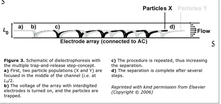
The multi-step dielectrophoresis concept
Figure 3. Schematic of dielectrophoresis with
the multiple trap-and-release step-concept.
a) First, two particle populations (X and Y) are
focused in the middle of the channel (i.e. at
L0/2.
b) The voltage of the array with interdigited
electrodes is turned on, and the particles are trapped.
c) The procedure is repeated, thus increasing
the separation.
d) The separation is complete after several
steps.
Reprinted with kind permission from Elsevier (Copyright © 2006)
Improving dielectrophoretic separations
A common method for separating particles with dielectrophoresis is to have a flow-through system where one population of particles is trapped whereas another population of particles is unretained. Another concept is based on trap-and-release. In the last method, particles with dissimilar mobility will travel a different distance before they are trapped, and when the voltage is turned off and the particles are relea-sed, they will exit the system with some degree of separation. If the difference in mobility be-tween the different populations is large enough, they will be completely fractionated. However, the trap-and-release method is not powerful enough if the mobility difference is small. One possibility is to repeat the trap-and-release pro-cedure several times [Paper II]. As this process is repeated, the degree of fractionation will be gradually enhanced even if two populations on-ly are slighton-ly separated in the first step.
Dielectrophoretic resolution and selectivity To quantify the degree of fractionation
obtai-B A DEP 3 w w d R + = (7)
where d is the distance between the two centers of each particle population, and w is the distan-ce between the particles most far apart within each population. It may either be written as a function of number of separation steps
DEP R DEP(N) C N
R = ⋅ (8)
or as a function of »dielectrophoretic selectivi-ty«, α , DEP
DEP DEP(α)= Cα ⋅α
R (9)
where α , is defined as DEP
X DEP, Y DEP, X DEP, DEP ϑ ϑ ϑ α = − , ϑ >ϑ (10)
matography. Using the definition in Equation 7, the two particle populations will be comple-tely separated if RDEP > 1.5.
Enhanced separation power
As in the example calculated for the superposi-tioned dielectrophoresis concept, the new met-hod of multi-step dielectrophoresis is demon-strated with a model consisting of a micro channel with electrode arrays at the top and the bottom of the channel. In this model, dielectric data for polystyrene beads suspended in deion-ized water were used [27]. At the start of the run, the particles were assumed to be focused in the middle of the channel, and when the vol-tage was turned on, the particles were transpor-ted to different positions downstream in the channel. The distances the particles are dis-placed before ending at an electrode edge de-pends on their hydrodynamic and dielectric properties. After being trapped, they are relea-sed and re-focurelea-sed in the middle of the chan-nel. If the difference in dielectrophoretic beha-vior between the particles is large enough, they are completely separated in just one trap-and-release step. If the difference is small, the pro-cedure is repeated, which leads to an increased resolution as the particles are moving down-stream in the channel (Figure 3).
Results from the calculation show that it is easiest to separate particles with different size (Figure 4) compared to different dielectric pro-perties. This agrees with the fact that the radius of the particle is quadratically proportional to the mobility, whereas the dielectric properties only affect the mobility in a linear way. Diffe-rences in conductivity have a larger influence on the separation possibilities than differences in permittivity. This is consistent with the fact that the conductivity is mainly governed by the surface properties, whereas the permittivity is determined by bulk properties.
A complete separation (i.e. RDEP > 1.5) may
be achieved in two trap-and-release steps if the difference in size is 5 %. If the size difference is 0.5 %, 20 steps are required, and with 200 steps it is possible to separate particles with a size difference as small as 0.2 %. For a particle
0 1 2 3 4 0 0.5 1 1.5 2 Number of steps Reso lu ti o n 5 % 2 % 1 % 5 % 2 % 1 % B 15 20 25 0 0.5 1 1.5 2 2.5 Number of steps Reso lu ti o n 0.5 % C 1800 200 220 0.5 1 1.5 2 2.5 Number of steps Re so lu ti o n 0.2 %
Figure 4. Calculated resolution as a function
of the number of steps in size-based separa-tion.
A) Relative differences in size: 5 %, 2 % and
1 %.
B) Relative difference in size: 0.5 %. C) Relative difference in size: 0.2 %. Reprinted with kind permission from Elsevier (Copyright © 2006)
with 5 µm radius, this difference corresponds to a 10 nm coating.
As mentioned above, differences in conducti-vity have a higher impact on the separation than differences in permittivity. Arnold et al. [27] have shown that the conductivity differen-ce between a set of boiled and unboiled COOH-coated polystyrene is 31 %. According to the model calculations, this difference is too small to enable a complete separation with one a single trap-and-release step. It should however be possible to separate such particles by repea-ting the trap-and-release step only once. Using four steps, the required conductivity difference drops to 19 %. Below this value, the separation possibilities are very poor. A decrease in
diffe-rence with just a few percent makes separation practically impossible.
For situations close to this limit of separa-tion, many steps are required. Fifty steps would correspond to approximately 1500 electrode pairs (assuming that there are 15 electrodes uti-lized in each step). With particles around 5 µm in radius, the necessary channel length would be 15 cm. This is a fairly long channel, but still feasible for a lab-on-a-chip-system [28]. If the differences in dielectric properties are smaller than the critical values necessary to obtain any separation, some of the values for the system parameters, such as electrode width, electrode gap, voltage, etc. must be changed.
Calculation methods
Model particles
As previously mentioned, the calculations de-monstrating the proposed concepts were per-formed using Escherichia coli (E. coli) and poly-styrene beads as model particles. Dielectric and morphological data were obtained from the li-terature [27, 29]. Using these data, the mobili-ties could be calculated [20, 30–31]. The re-sults are shown in Figure 5. The evaluation was made by calculating the trajectories of the mo-del particles. To obtain the trajectories, the electric field and the fluid velocity in different parts of the system was determined using the fi-nite element method in combination with a numerical method for forward stepping.
Model chambers
The model channel in which the separation is performed has a rectangular cross section with a width much larger than the height, hence allo-wing the calculations to be performed in a 2D plane in the direction of the flow. Both the top and the bottom of the channel are covered with an array of interdigitated electrodes [23–26]. The two arrays are connected to different signal generators, thus allowing different frequencies to be applied on the top and the bottom. This is useful if superpositioned fields are utilized. The electrodes in each array are connected in pairs so that the voltage phase angle between two adjacent electrodes is 180°.
Calculation procedure
The calculation procedure included three steps. First the electric potentials at all positions in the model system were calculated. Using that information, the gradient of the squared elec-tric field could be determined. Secondly, the fluid flow in all positions had to be determined. Combining the data from the first and the se-cond step, the particle trajectories could be de-termined in a third step.
The gradients of the squared electric field were calculated by solving the Laplace equation for the electric potential, using the finite ele-ment method and standard boundary
condi-tions [23]. In this method, the area is first divi-ded into small elements using a mesh of tetra-hedron units. The mesh units are smaller near the electrode edges, and grow with distance from the edges. The mesh was created in 3D using Fluent’s mesh generation software Gam-bit [32], which also allowed different boundary A 102 104 106 108 1010 -2 -1 0 1 2 3 x 10-11 Frequency [Hz] M obili ty of E . c o li [ m 4V -2s -1] 2.3 mS/cm 1.3 mS/cm B 102 104 106 108 1010 -1.5 -1 -0.5 0 0.5 1 x 10-18 Frequency [Hz] M o b ili ty of be a d [ m 4V -2s -1]
Figure 5. A) Calculated dielectrophoretic
mobility for E. coli in suspension media with different conductivity (1.3 mS/cm and 2.3 mS/cm).
B) Calculated dielectrophoretic mobility for
a polystyrene bead (conductivity 2.0 µS/cm, relative permittivity 2.5 and a diameter of 10 µm) in deionized water (conductivity 0.66 µS/cm, relative permittivity 80 and
viscosity 1·10–3 kg/m3s), as a function of
frequency.
Reprinted with kind permission from Elsevier (Copyright © 2006)
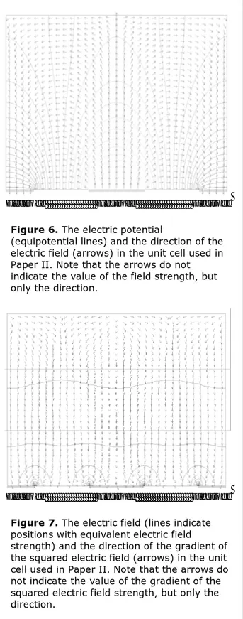
conditions to be applied. The meshes were re-fined adaptively and emerged in FemLego [33] during the computation procedure. When the electric potential in all elements were calcula-ted, the gradients could be calculated. An example of the appearance of the electric poten-tial and the electric field is displayed in Figure 6 and Figure 7.
Electrode Electrode Electrode
Figure 6. The electric potential
(equipotential lines) and the direction of the electric field (arrows) in the unit cell used in Paper II. Note that the arrows do not indicate the value of the field strength, but only the direction.
Electrode Electrode Electrode
Figure 7. The electric field (lines indicate
positions with equivalent electric field
strength) and the direction of the gradient of the squared electric field (arrows) in the unit cell used in Paper II. Note that the arrows do
The plots were created in FemLab [34] using the finite element method with the same boun-dary conditions as in the calculations used for determining the particle trajectories.
The velocity of the fluid can be calculated from the Navier-Stokes momentum balance and the mass conservation. In the model sys-tems used in this thesis, the dimensions are small, and therefore the flow can be assumed to be laminar. The simple geometry then allows the Navier-Stokes equations to be solved analy-tically. The analytical solution for the flow is the well known parabolic profile.
Finally, the Forward Euler method was used to compute and trace the position of one par-ticle. In that method, a small step is made in the direction of the force. From the new point, another small step is taken in the direction of the force in that point. This is repeated until the particles are positioned at a distance from the wall approximately equal to the radius of the particle. MatLab [35] was used to plot the trajectories of the particles.
To simplify the calculations and to be able to easily compare different calculations, the equa-tions were put in a dimensionless form, which facilitates rescaling.
Concentrated suspensions
In the calculations supporting the two new concepts, the suspensions were assumed to be diluted enough to allow particle-particle inter-actions to be neglected. To obtain correct pre-dictions of the behavior of concentrated par-ticles, a new method for motion induced by inter-particle forces has been investigated [Pa-per III]. The method provides good efficiency and accuracy. It is based on a molecular dyna-mics (MD) approach [36] which makes it pos-sible to include several different forces (hydro-dynamic forces, electrostatic forces and dielect-rophoretic forces) without making the calcula-tions too time-consuming. In this way, the be-havior of a concentrated suspension of polari-sable particles may be predicted. The well known formation of pearl-chain structures was also investigated (Figure 8). This behavior was qualitatively confirmed by experimental dielect-rophoresis work as depicted in Figure 13.
pearl-chain formation is less likely to occur close to the electrode edges, which is also the case for the bulk flow region where the
dielect-chain formation takes some time, thus it should not be a limiting factor in a trap-and-release system. A Electrode B Electrode Electrode C Electrode Electrode Electrode
Figure 8. Calculated prediction of the behavior
of polarisable particles between two pointed electrodes (A and B). Compare with the photo-graphs in Figure 13.
A) Initial distribution of particles. B) Pearl chains are forming.
C) The pearl chains move toward the electrode
tips where the dielectric force is strongest.
Reprinted with kind permission from ASME (Copyright © 2006)
The cross-flow filtration method
for conductivity measurements
Gentle pre-handling of cells
When making predictions on dielectrophoretic behavior, it is of great importance that relevant values of dielectric properties such as conducti-vity are available. Cross-flow filtration is suitab-le for handling suspensions of bacteria and yeast [37] and it reduces the osmotic shock [16–17] which is normally induced when stan-dard conductivity measurement procedures, which include repetitive centrifugation and re-suspension, are employed [14, 16, 38].
Isoconductance point
The conductivity of a particle suspension does not only depend on the suspension medium, but is also affected by the suspended particles. A method for determining the conductivity of particles is to vary the conductivity of the me-dium until it reaches the same value as the con-ductivity of the suspension [38]. This value is commonly referred to as the isoconductance point, because here the conductivity of the sus-pension is the same as the conductivity of the particles. An accurate determination of the vo-lume fraction is usually a difficult task, and a great advantage of using this method is that it is independent of the particle volume fraction (as long as the volume fraction is not too low) [16].
Preparation of B. subtilis
A Bacillus subtilis strain CCUG 1638 (Culture Collection University of Gothenburg) was ino-culated in sterile Tryptone Soya Broth (Oxoid) overnight. Optical density measurements at 600 nm (OD600) were performed to monitor
the cell-growth. At harvest, the optical density was 2.2. This corresponds to 4·108
colony for-ming units (cfu)/ml.
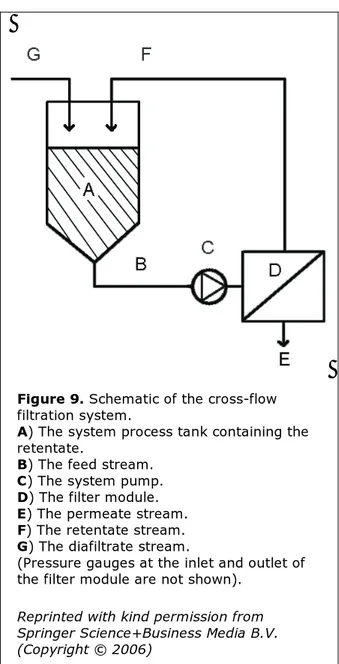
Figure 9. Schematic of the cross-flow
filtration system.
A) The system process tank containing the
retentate.
B) The feed stream. C) The system pump. D) The filter module. E) The permeate stream. F) The retentate stream. G) The diafiltrate stream.
(Pressure gauges at the inlet and outlet of the filter module are not shown).
Reprinted with kind permission from Springer Science+Business Media B.V. (Copyright © 2006)
is initially filled with 250 mL of the bacterial suspension. 150 mL permeate is removed. The remaining 100 mL of the retentate is then se-micontinously diafiltrated by removal of 10 to 25 ml permeate followed by addition of a cor-responding volume of diafiltrate (10 mM po-tassium phosphate). During the diafiltration at
Conductivity of gently treated cells
The difference between the conductivity of the suspension and the medium is plotted as a function of the conductivity of the medium. When the difference is zero, the conductivities of the medium, suspension and bacteria are equal [38]. Hence, the isoconductance point is to be found at the intersection between the x-axis and the plotted curve. Using the least squa-re-method, a straight line is fitted to the data (Figure 10). The intercept of the curve was found to be 270 ± 52 µS/cm, and the slope be-comes –0.042 ± 0.006 (both with a 95 % con-fidence limit). Three separate experiments on three different B. subtilis cultures yielded a con-ductivity of 7000 ± 1500 µS/cm (using a one-sample t-test with a 95 % confidence limit). Previous reports on the conductivity of B.
sub-tilis [14] state a value of 935 ± 96 µS/cm.
Hen-ce, the value obtained in this study is almost an order of a magnitude higher than reported in previous studies. This discrepancy is anticipa-ted to be due to the differences in cell treat-ment during the measuretreat-ments. The cross-flow filtration allows the osmotic potential of the suspension medium to be changed little by litt-le from the starting value, thereby exposing the micro-organisms to less osmotic stress.
Figure 10. Conductivity difference between
retentate and permeate during cross-flow fil-tration as a function of the conductivity of the permeate. The straight line (solid) is fitted to
data (coefficient of determination, R2
=0.974). The isoconductance point is at the intersection between the line and the x-axis (6600 µS/cm). The two curved (dashed) lines show the 95 % confidence limit prediction intervals.
Reprinted with kind permission from Springer Science+Business Media B.V.
Dielectrophoresis experiments
Preparation of beads and bacteria
A mixture of polystyrene beads with diameters of 0.5 and 2.0 µm were utilized. The beads were initially suspended in an aqueous solution. A sample of the suspension was centrifuged at 5000 rpm for 3 minutes, the medium was re-moved, and the beads were suspended in deio-nized water. Samples of beads with different conductivity were made by adding KCl or MilliQ water to the beads suspension.
E. coli K-12 bacteria of the genetically
modi-fied strain W3110 were cultured batch-wise in a complex medium at 37 °C, 35 % dissolved oxygen and pH 7.0 using a 1 L fermenter (Be-lach AB, type SARA). Samples were withdrawn from the culture at regular intervals. The samp-les were centrifuged, the medium removed and the pelleted bacteria frozen at –20 °C. Bacterial growth was monitored by measuring light ab-sorbance at 550 nm (A550) using a
spectropho-tometer, and by standard dry-weight determi-nation. The frozen bacteria were thawed and washed three times with deionized water prior to dielectrophoresis. The conductivity of the cell suspension was modified by adding known amounts of NaCl solution.
Open dielectrophoresis device
The experimental devices were designed to po-sition particles at a desired spot or in different patterns. They were also designed to be easy to use, clean, and reuse.
The basic platform for the dielectrophoresis device was a glass plate equipped with thin-film Ti- or Al-electrodes. The electrode geometries were dimensioned to suite the size of the par-ticles used in the experiments. Different elect-rode shapes and positioning patterns were tes-ted (tip distance 10 or 30 µm, point angle 90 or 110 degrees, and spacing 30 or 100 µm), and straight interdigitated geometries of 10 µm width and 15 µm spacing. The pointed electro-des were electro-designed to produce a very high
elect-tween the electrodes. Single pairs and arrays of up to 50 electrodes were used.
Figure 11. Schematic of the
dielectrophore-sis set-up used in the experiments. The de-vice consists of a glass microscope slide (A) with Ti electrodes (B). The suspension (C) is deposited drop-wise directly onto the sur-face, and enclosed with a standard cover glass (D).
Microfabrication of the dielectrophoresis de-vice was a one-mask lithography process of a Ti layer on the glass substrate. The substrate used was standard soda-lime glass, 76 x 35 mm, thickness 2 mm, which was cleaned using stan-dard procedures. The Ti-layer was deposited by sputtering onto the glass to form a layer with a thickness of 0.20 µm. Photolithography of Shi-pley-1813 positive photo resist was used for patterning and the excess Ti was removed by etching in buffered HF-solution (5 vol-% HF buffered with ammonium fluoride). The photo resist was removed in acetone and the substrate was then spin dried. Electrical connection to the electrodes was achieved by bonding wires to the contact pads using conductive epoxy glue. The substrate can easily be upgraded to a flui-dic device by mounting of a piece PDMS with a moulded channel and in/out connections on top of the electrode platform (Figure 11). In
A B C D Function generator Fluorescence microscope Dielectrophoresis chip
Coolpix) (Figure 11). To apply the electric field, a function generator (TTi TG-120) was connected to the device via the wires of the micro dielectrophoresis chip. In order to check the electric field, an oscilloscope (GW Instec GOS-620, 20 MHz) was used. The particle suspension was dispensed drop-wise onto the electrode-glass system and covered with a stan-dard cover glass for light microscopy. In the experiments, sine waves at frequencies from 100 Hz up to 20 MHz and voltages from 0 to 20 V peak to peak were used. The response of the particles to the applied electric field was studied using a fluorescence microscope.
After each experiment, the plates with elect-rodes were washed with 70 % ethanol and MilliQ water and then dried with nitrogen gas. Cleaned in this way, the device could be used for more than 30 consecutive experiments, and no decrease in performance could be observed. Positioning and separation of beads
Dielectrophoretic positioning of polystyrene beads in rows was performed using an array of interdigited electrodes. The sample contained a mixture of 2 µm and 0.5 µm diameter beads. The conductivity of the sample was 8 µS/cm. At low frequency (10 kHz) the beads stick to
sing the frequency to 4.0 MHz, the 0.5 µm beads were affected by a negative dielectropho-retic force and also positioned themselves in rows. An interaction effect was seen, where the particles formed pearl chains with nearby sur-rounding particles.
Behavior of E. coli
The dielectrophoretic behavior of E. coli cells was also demonstrated using the pointed elec-trodes. The bacteria were exposed to an electric field of frequencies between 10 kHz and 20 MHz. At the lower frequencies, the bacteria li-nearized and pearl-chains were formed (Figure 13). When the frequency was increased, the pearl-chain formation became more pronoun-ced and the particles drifted towards the gap between the electrode tips. At higher frequen-cies, about 3 MHz and above, rotation was ob-served and the pearl-chains seemed distorted when increasing the frequency further. At fre-quencies above 10–15 MHz, the bacteria chan-ged orientation and linearized orthogonally to the field. Pearl-chains of bacteria oriented in the same direction were also observed. With the suspensions used, no repelling action was noted.
A B C
Figure 12. Dielectrophoresis of a mixture
containing 0.5 and 2.0 µm fluorescent polystyrene beads at interdigited electrodes with an applied voltage of 10V.
A) At an AC frequency of 100 kHz, both
particle populations are attracted to the electrode edges.
B) At 1.40 MHz, the 2.0 µm beads experience
a repelling dielectrophoretic force and are positioned in the rows between the electrodes.
C) At 4.0 MHz, the 0.5 µm beads also
experience a repelling force. All particles are now positioned between the electrodes.
A B C
Figure 13. Behavior of E. coli cells under
influence of dielectrophoresis.
A) At 10 kHz, the bacteria are orientated
vertically, and some pearl-chains are formed.
B) At 2 MHz, the particles are strongly
attracted by the electrode edges, especially towards the pointed tips.
C) At 20 MHz, the bacteria orient themselves
horizontally, and some rotation at the electrode edges is observed.
Conclusions and future outlook
When determining the conductivity of living cells, the incorporation of cross-flow filtration should result in more accurate values as well as a reduced degree of cell destruction to conven-tional methods. It should be possible to minia-turize the equipment and to run in a conti-nuous mode, which would make it feasible to integrate it with dielectrophoretic chip-based separation systems. This may be particularly useful when manual handling must be avoided,
e.g. when dealing with hazardous organisms or
in cases where only very small amounts of ma-terial are available.
The concept of trapping particles with super-positioned dielectrophoresis is particularly use-ful in cases where the conductivity of the sus-pension medium has to be high. The overall flow rates and throughput are small under such conditions, but this may still be acceptable when dealing with living cells and where a high survival rate of the cells is of key priority. Ope-ration with superpositioned fields also offer an extended possibility for fine tuning and impro-ved selective trapping of particles according to shape and dielectric properties.
The multi-step dielectrophoresis concept based on repetitive dielectrophoretic trap-and-
release in a flow system could provide entirely new possibilities for e.g. production of mono-disperse materials or cell separation. Model cal-culations for polystyrene beads predict that it should be possible to obtain a complete separa-tion of particles with a 0.2 % size difference by performing approximately 200 trap-and-release steps. Since the particles are refocused in every step, the resolution increases linearly with the number of steps. The improved separation po-wer could be of great interest for fractionation of particles with small differences in surface conductivity, and applications can be envisio-ned in connection with flow-based affinity-based assays. There seems to be a limiting value of conductivity difference, below which no se-paration can be obtained. For the model system used for calculations in this thesis, this limiting value was 18 % difference in conductivity.
The preliminary practical tests which have been performed have shown that the behavior of living cells was as predicted by theoretical models. In conclusion, it can be said that the described new methods have shown a promi-sing potential for improved separations. How-ever, further experimental work is now required to validate the proposed concepts.
Acknowledgements
I would like to express my sincere gratitude to my supervisor professor Johan Roeraade for gi-ving me the opportunity to begin my research studies in his group and for teaching me the secrets of scientific writing.
Special thanks to my co-writers and co-wor-kers: Yuan Lin, LarsErik Johansson, Gustav Amberg, Sven Hamp, Gunnar Jonsson, Mats Jönsson, Ulf Lindberg.
I would also like to thank other people who have helped me with this thesis, as well as past and present colleagues: Alf Jarméus, Kurt Ben-kestock, Johan Jacksén, Johan Sjödahl, Anders Björk, Lisa Skedung, Catharina Silfwerbrand-Lindh, Johan Pettersson, Jonas Bonn, Patrik
Ek, Olof Nord, Mårten Stjernström, Anders Hanning, Suguru Uemura, Theres Redeby, Åsa Emmer, Martin Kempka, Erik Litborn, Lars-Göran Danielsson, Helene Andersson, Per Bingefors, Gerd Eriksson, Laila Mannsdorff, Sten Johansson, Rolf Jansson, Peter Lindberg, Erik Furusjö, Matthew Rice, Mario Curcio, Ola Berntsson, Xiaotian Yang, Andreas Wolde-giorgis, Adam Kloskowski, Gustav Sundqvist, and many more…
This work had not been possible without Sara and my family!
The financial support from SSF (The Swe-dish Foundation for Strategic Research) is gratefully acknowledged.
References
[1] Andersson H., v d Berg A., »Micro-fluidic devices for cellomics: a review«,
Sens. Actuators B 92 (2003) 315
[2] Erickson D., Li D., »Integrated micro-fluidic devices«, Anal. Chim. Acta 507 (2004) 11
[3] Yi C., Li C.-W., Ji S., Yang M., »Microfluidics technology for mani-pulation and analysis of biological cells«, Anal. Chim. Acta (2006), in press
[4] Hughes M. P., »Strategies for dielectrophoretic separation in laboratory-on-a-chip systems«,
Electrophoresis, 23 (2002) 2569
[5] Gascoyne P. R. C., Vykoukai J., »Particle separation by dielectro-phoresis«, Electrophoresis 23 (2002) 1973
[6] Cen E. G., Dalton C., Li Y., Adamia S., Pilarski L. M., Kaler K. V. I. S., »A combined dielectrophoresis, traveling wave dielectrophoresisand electro-rotation microchip for the mani-pulation and characterization of human malignant cells«, J. Microbiol.
Methods 58 (2004) 387
[7] Tanke H. J., v-d-Keur M., »Selection of defined cell types by flow-cytometric cell sorting«, Tibtech 11 (1992) 55 [8] Cheung K., Gawad S., Renaud P., »Impedance spectroscopy flow cyto-metry – On-chip label-free cell diffe-rentiation«, Cytometry A 65A (2005) 124
[9] Reschiglian P., Zattoni A., Roda B., Michelini E., Roda A., »Field-flow fractionation and biotechnology«,
TRENDS in Biotechnology 23 (2005)
475
[10] Wang X. B., Vykoukal J., Becker F. F., Gascoyne P. R., »Separation of
polystyrene microbeads using dielectrophoretic gravitational field-flow-fractionation«, Biophys. J. 74 (1998) 2689
[11] Wang X. B., Yang J., Huang Y., Vykoukal J., Becker F. F., Gascoyne P. R., »Cell separation by dielectro-phoretic field-flow-fractionation«,
Anal. Chem. 72 (2000) 832
[12] Pohl H. A., »The motion and percipitation of suspensoids in
divergent electric fields«, J. Appl. Phys. 22 (1951) 869
[13] Pethig R., Markx G. H., »Applications of dielectrophoresis in biotechnology«,
Tibtech 15 (1997) 426
[14] Markx G. H., Talary M. S., Pethig R, »Separation of viable and non-viable yeast using dielectrophoresis«, J.
Biotech. 32 (1994) 29
[15] Docoslis A., Kalogerakis N., Behie L. A., Kaler K. V. I. S., »A novel
dielectrophoresis-based device for the selective retention of viable cells in cell culture media«, Biotech. Bioeng. 54 (1997) 239
[16] v d Wal A., Minor M., Norde W., Zehnder A. J. B., Lyklema J.,
»Conductivity and dielectric dispersion of gram-positive bacterial cells«, J.
Colloid Interface Sci. 186 (1997) 71
[17] Morbach S., Krämer R., »Body shaping under water stress:
osmosensing and osmoregulation of solute transport in bacteria«,
[18] Fuhr G., Glasser H., Müller T., Schnelle T., »Cell manipulation and cultivation under AC electric fiels influence in highly conductive culture media«, Biochim. Biophys. Acta 1201 (1994) 353
[19] Choi L., »Secretory and extracellular production of recombinant proteins using Escherichia coli«, Appl. Microbiol.
Biotechnol. 64 (2004) 625
[20] Morgan H., Green N. G., AC
Electro-kinetics: colloids and nanoparticles,
Research Studies Press, Baldock, Hertfordshire, UK (2003) 297
[21] Hughes M. P., Pethig R., Wang X.-B., »Dielectrophoretic forces on particles in travelling electric fields«, J. Phys. D:
Appl. Phys. 29 (1996) 474
[22] Pethig R., Talary M. S., Lee R. S., »Enhancing traveling-wave dielectro-phoresis with signal superposition«,
IEEE Eng. Med. Biol. Mag. 22 (2003)
43
[23] Green N. G., Ramos A., Morgan H., »Numerical solution of the dielectro-phoretic and travelling wave forces for interdigitated electrode arrays using the finite element method«, J. Electrostat. 56 (2002) 235
[24] Holmes D., Green N. G., Morgan H., »Microdevices for dielectrophoretic flow-through cell separation«, IEEE
Eng. Med. Biol. Mag. 22 (2003) 85
[25] Li H., Bashir R., »On the design and optimization of micro-fluidic dielectro-phoretic devices – a dynamic
simulation study«, Biomed.
Microdevices 6 (2004) 289
[26] Suzuki M., Yasukawa T., Mase Y., Oyamatsu D., Shiku H., Matsue T., »Dielectrophoretic micropatterning with microparticle monolayers covalently linked to glass surfaces«,
Langmuir 20 (2004) 11005
[27] Arnold W. M., Schwan H. P., Zimmermann U, »Surface
conductance and other properties of latex particles measured by electro-rotation«, J. Phys. Chem. 91 (1987) 5093
[28] Manz A., Becker H., Microsystem
Technology in Chemistry and Life Sciences, Springer-Verlag Berlin
Heidelberg, Germany (1999) [29] Asami K., Hanai T., Koizumi N.,
»Dielectric analysis of Escherichia coli suspensions in the light of the theory of interfacial polarization«, Biophys. J. 31 (1980) 215
[30] Asami K., Yonezawa T., »Dielectric behavior of non-spherical cells in culture«, Biochim. Biophys. Acta 1245 (1995) 317
[31] Morgan H., Green N. G.,
»Dielectrophoretic manipulation of rod-shaped particles«, J. Electrostat. 42 (1997) 279
[32] http://www.fluent.com
[33] Amberg G., Tönhardt R., Winkler C., »Finite element simulations using symbolic computing«, Math. Comp
Sim. 49 (1999) 257
[34] http://www.comsol.com [35] http://www.mathworks.com/ [36] Elimelech M., »Particle deposition and
aggregation: measurement, modelling and simulation«, J. Chem. Phys. 63 (1975) 2376
[37] Cheryan M., Ultrafiltration Handbook,
Technomic Publishing Company, Inc Lancaster, PA, USA (1998) 527 [38] Yunus Z., Mason V., Verduzco-Luque
C. E., Markx G. H., »A simple method for the measurement of bacterial particle conductivities«, J. Microbiol.