Faculty of Technology and Society Computer Engineering
Bachelor thesis 15 credits
Establishing a suitable middleware based on reconstruction and
repeating patterns
Fastställande av en passande mellanprogramvara baserat på rekonstruktion och upprepande mönster
Jesper Hansen
Peter Johansson
Exam: Bachelor of Science in Engineering Subject area: Computer Engineering Date of final seminar: 2016-06-01
Supervisor: Dr. Ulrik Eklund Examiner: Dr. Mia Persson
Abstract
In distributed systems, components communicate by passing messages between each other and a middleware bridges gaps between the interaction of different applications. The aim was to investigate and analyse middleware designs that handle a one-to-many communication usable in XFS based software and identify possible problems during the development process.
Reverse engineering was used to reconstruct our stakeholders XFS based software. Entry and exit points were localised and visualised with UML diagrams from the reconstruction. By fo-cusing on the stakeholders requirements and the reconstruction, the design pattern Broker and Reactor were used to decouple a one-to-one relationship towards the stakeholders hardware. The architecture of the middleware prototype was based on a client-server architecture and the prototype utilises a one-to-many inter-process communication that sends JSON messages over a pipe connection.
The prototype was evaluated using written test cases and the test cases presented satisfactory results. The final version of the prototype was able to handle several clients communicating with the stakeholders hardware through the server and all clients displayed callbacks.
Choices made during the iterative development identified problems that are valuable to other developers. The two main problems were high complexity in a legacy software system and that all logic in the XFS standard is open to interpretation. Our solution is successful as a start-up approach but asynchronous patterns are determined as a possible optimisation for the software system.
Keywords: Distributed systems, Middleware, XFS, Inter-process communication, JSON, Pipes, Reconstruction, UML, Patterns
Sammanfattning
I distribuerade system, kommunicerar komponenter genom att skicka meddelanden till varan-dra och mellanprogramvara överlappar integrationen mellan olika applikationer. Syftet var att undersöka och analysera olika designmönster till en mellanprogramvara som hanterar kommu-nikationen i en en-till-många relation och som kan användas i en XFS baserad programvara samt identifiera eventuella problem som uppkom under utvecklingsprocessen.
Reverse engineering användes för att rekonstruera vår uppdragsgivares XFS baserade mjuk-vara. Ingång- och utgångspunkter lokaliserades och visualiserades med hjälp av UML-diagram. Med hjälp av vår uppdragsgivares krav och rekonstruktion av deras mjukvara, de designmön-ster som valdes var Broker och Reactor. Dessa valdes för att frikoppla en-till-en relationen mot vår uppdragsgivares hårdvara. Arkitekturen i vår prototyp av mellanprogramvaran baserades på klient-server och prototypen använder en en-till-många interprocesskommunikation för att skicka JSON-meddelande över en pipe anslutning.
Prototypen utvärderades med hjälp av testfall och utfallet av testen var till belåtenhet. Slutver-sionen av vår prototyp klarade av att hantera kommunikation mellan flera klienter till vår upp-dragsgivares hårdvara genom en server. Callbacks hanterades och presenterades i alla klienter.
Valen som gjordes under utvecklingen identifierade problem som är värdefulla för andra utveck-lare. Två huvudproblem uppstod för att det är väldigt hög komplexitet i välutvecklade system samt att logiken bakom XFS standarden är öppen för fri tolkning. Vår lösning är bra vid en utvecklingsuppstart men det fastställs att asynkrona mönster är en möjlig optimering av mjuk-varusystemet.
Keywords: Distribuerade system, Mellanprogramvara, XFS, Interprocesskommunikation, JSON, Pipes, Rekonstruktion, UML, Mönster
Acknowledgements
We would like to thank SCAN COIN, and especially Ola Söderström, for giving us an oppor-tunity to work with their XFS based software and hardware and for helping us during the development. We would like to thank our supervisor Dr. Ulrik Eklund for all his guidance and feedback on our thesis. Finally, we would like to thank our families that supported and helped us throughout this thesis.
List of Abbreviations
ADD - Attribute-Driven Design
API - Application Programming Interface CEN - European Committee for Standardization DLL - Dynamic Link Library
FIFO - First In First Out
IDE - Integrated Development Environment IPC - Inter-Process Communication
JSON - Javascript Object Notation SPI - Serial Peripheral Interface
SRS - Software Requirements Specification UML - Unified Modeling Language
XFS - Extension for Financial Services XML - Extensible Markup Language
Contents
1 Introduction 1 1.1 Background . . . 1 1.2 Research aim . . . 2 1.3 Research question . . . 2 1.4 Limitations . . . 3 2 Teoretical background 4 2.1 Distributed computing . . . 4 2.1.1 Middleware . . . 4 2.1.2 Pipes . . . 5 2.1.3 Sockets . . . 5 2.2 Serialization formats . . . 62.2.1 JSON - Javascript Object Notation . . . 6
2.2.2 XML - Extensible Markup Language . . . 6
2.3 Software architecture . . . 7
2.3.1 Re-engineering . . . 7
2.3.2 Design patterns . . . 7
2.4 XFS - Extensions for Financial Services . . . 7
2.4.1 Hardware - Coin acceptor . . . 8
3 Related work 9 3.1 Mitchell J, Sanchez-Ruiz A - An architectural pattern for adaptable middleware infrastructure . . . 9
3.2 Y. Liang et al. - Study on Service Oriented Real-time Message Middleware . . . 9
3.3 Rubel P et al. - Fault Tolerant Approaches for Distributed Real-time and Em-bedded Systems . . . 10
3.4 Liu X, Ma L, Liu Y - A Middleware-based Implementation for Data Integration of Remote Devices . . . 11
3.5 Hsu K, Leu J - Improving the efficiency of presence service in IMS by JSON . . . 11
4 Method 13 4.1 Construct a conceptual framework . . . 13
4.2 Develop a systems architecture . . . 14
4.3 Analyse and design the system . . . 15
4.4 Build the prototype . . . 16
4.5 Observe and evaluate the system . . . 16
5 Results and Evaluation 17 5.1 Software Requirements Specification . . . 17
5.2 Reconstruction . . . 17
5.2.1 Evaluation of Reconstruction . . . 20
5.3 Prototype development . . . 21
5.3.1 Serialization format . . . 21
5.3.2 Design pattern . . . 21
5.3.3 Architecture and design . . . 21
5.3.4 Integration . . . 23
5.3.5 Evaluation of Prototype . . . 25
5.5 Controlled Experiments . . . 27
5.5.1 Test Cases . . . 27
5.5.2 Results . . . 28
5.5.3 Analysis of Test Cases . . . 29
5.6 Evaluation of Requirements . . . 31
6 Conclusions and further work 32 6.1 Research Question . . . 32
6.2 Findings . . . 32
6.3 Further Work . . . 33
6.4 Contributions . . . 33
Appendix A Diagram A-1
1
Introduction
This chapter introduces the background of this thesis. Also research aim, research question and limitations are introduced.
1.1 Background
In distributed systems, the concept of passing messages is used between cooperating network components. The client-server model and the peer-to-peer model are well known models of this system. The common client-server role describes a client making requests to a server and the server responds to that request. In peer-to-peer, both sides act as client and server at the same time. The stakeholder for this thesis is SCAN COIN [1] and their software is based on a client-server model.
SCAN COIN develops and sells products and solutions for deposit, withdrawal, counting and sorting of coins and notes, complete with hardware and software. Their hardware products include sensors, coin acceptors, note acceptors, card readers, receipt printers and pin pad ter-minals. The coin acceptor and all software products are made in-house.
The software in SCAN COINs products is based on a client-server model titled Extension for Financial Services (XFS) [2]. XFS is a standard that defines a multi-vendor software interface to financial devices and its specifications are developed by European Committe for Standard-ization (CEN), in collaboration with over 20 companies.
Today, SCAN COIN has a one-to-one relationship between their XFS based software and hard-ware, because the hardware can only handle one request at a time. SCAN COIN requests a many solution so that many applications can connect to one hardware device. A one-to-many relationship would let applications simultaneously communicate and monitor a hardware device.
At the same time, SCAN COIN has begun to develop a new Dynamic Link Library (DLL) [3] interface on top of their coin acceptor. A DLL is a code library that is linked either at run-time or at load-run-time and SCAN COINs new DLL will replace the Java drivers used today. The java drivers are bound to a license fee and SCAN COIN is now interested in a proof-of-concept that a one-to-many relationship is achievable between their new DLL and existing software.
Middleware resembles a glue that bonds software components together and this glue handles the communication between them [4]. Middleware is often used with distributed systems because there are growing demands that they need to provide scalability, reliability, predictability and secure quality of service. There are also differences in hardware architectures, many different operating systems and network platforms [5]. These reasons make it is impossible to build the perfect system from the ground up and eventually, middleware implementations become neces-sary. However, software developers can build complex middleware designs and implementations with the help of patterns.
Using patterns is a effective way to build software, because patterns are reusable successful software models, designs and implementations to proven solutions. Since they are reusable, us-ing patterns prevents a necessity to rediscover and reinvent common software artifacts and avoid software traps and pitfalls [5]. Patterns offer a thinking process in pairs of problem-solution that is considered an expert behaviour and common in software engineering [6].
As mentioned above, middleware is sometimes an essential software implementation and com-bined with patterns, it becomes a powerful and reusable development technique. Different approaches can be utilised to design and implement a middleware solution in SCAN COINs software. One example is the binding of a host application and middleware to an interface, which separates the middleware from the application logic [7]. By using a middleware that replicates clients and server, it is possible to replicate a client-server relationship with many clients [8].
Another example is a modification to the publish-subscribe middleware, which decouples pro-ducers and consumers and this decoupled communication is necessary when implementing a one-to-many relationship [9]. By using the Publish-Subscribe pattern and implementing a transceiver with a message queue, reader/writer, parser/re-packer and a message forwarder, a middleware structure is created that bridges lower-level devices with upper-level software. This logic is also necessary when implementing a one-to-many relationship [10].
These examples use similar or resembling approaches that is necessary when designing a mid-dleware that suits SCAN COINs problem and requirements. This thesis will therefore be a contribution for solving a specific software problem in XFS based software; to enable a one-to-many relationship in a one-to-one environment between client and server/hardware.
First we introduce relevant theory in chapter 2 and in chapter 3, we summarise related work. In chapter 4, we provide an overview of the steps described in chapter 5. Last, we summarise our contribution and discuss future work in chapter 6.
1.2 Research aim
It is necessary to re-engineer SCAN COINs software because this ensures that the most suitable middleware solution, according to specification requirements, is implemented. Design patterns are used to accomplish a middleware architecture. The aim of this thesis is:
To investigate and analyse middleware designs that handle a one-to-many commu-nication usable for SCAN COINs software and implement a middleware prototype based on existing architecture and design analysis.
1.3 Research question
A research question was defined from the research aim. A result from the research aim was a middleware prototype, that was thoroughly tested in a test environment and implemented in SCAN COINs software. The research question is:
What difficulties emerges when implementing a client-server middleware usable for XFS based software?
This was achieved by dividing the question into two subproblems:
1. Design a suitable middleware prototype according to specification requirements, pattern analysis and reconstruction.
2. Implement and evaluate the proposed middleware solution in a controlled test environ-ment and in the software architecture in question.
1.4 Limitations
The reconstruction of SCAN COINs software architecture was limited to modelled UML dia-grams. These diagrams contain class diagrams, sequence diagram and deployment diadia-grams.
Only JSON and XML was used as text-based communication in the prototype. The selec-tion of the most favourable text-based format was limited to research results. Only sockets and pipes was used as communication technique in the prototype. The selection of the most favourable communication technique was limited to a performance comparison.
The prototype development was limited to the Integrated Development Environment (IDE) at SCAN COIN. The design of the prototype was limited to the reconstruction, design patterns and software requirement specifications. The requirements could be expanded with time. The prototype was evaluated with one specific hardware at SCAN COIN; a coin acceptor (see section 2.4.1).
2
Teoretical background
This chapter is about distributed systems, middleware, serialization formats, reverse engineer-ing, design patterns and XFS.
2.1 Distributed computing
A distributed system is a system that contains one or more components cooperating by net-work communication. The most common distributed systems are the Internet and the World Wide Web but distributed systems are also found in industrial automation, telecommunication, e-commerce, financial services, health care and entertainment [11].
Inter-process communication (IPC) is commonly used in distributed systems. IPC is the ability for processes and threads to communicate and share data between each other. IPC is both one-and two-way communication, where a single process or thread is able to act both as a client and server depending on the circumstances. Common IPC mechanism for Windows are Pipes and Windows Sockets [12].
Three techniques were developed that handles the distribution obstacles of inherent and ac-cidental complexities, inadequate methods and techniques and the endless reinvention and rediscovery of concepts and techniques. These techniques are ad hoc network programming, structured communication and middleware.
2.1.1 Middleware
Middleware is a distribution infrastructure software that sits between applications and operating system, network or hardware. The use of middleware is mainly to bridge the gap between how parts of applications are connected and interoperate with each other and the capabilities to pass messages and share data. The use of middleware is also to support and simplify component in-tegration developed by different technology suppliers. Two applications can communicate with each other without being directly connected.
If middleware is implemented correctly, developers can focus on application business logic re-quirements instead of low-level platform details. Middleware also reduces the cost for software lifecycles because previous development expertise on frameworks and services can be reused instead of reinvented every time, which increases software portability [11]. Figure 1 shows the presence of middleware.
A common area of use is applications that run on different platforms. This means a network of different operating systems and hardware components that need to communicate with each other. The network acts as a transport mechanism and middleware ensures that the commu-nication between them is functional, regardless of platform. Middleware can also be used for communication and data sharing between applications on a local machine. The use of middle-ware softmiddle-ware is versatile [4, 13].
2.1.2 Pipes
Pipes is a technique that allows processes and threads to communicate and send data between each other. Pipes was first developed for Unix based systems and the purpose of pipes is to allow programs to work together by redirecting the output of a program to the input of another program [14].
There are two types of pipes, anonymous and named pipes. Two main differences between named pipes and anonymous pipes are the absence of full-duplex communication for anony-mous pipes, which is the ability to communicate in both directions over a network, and the ability to have a one-to-many communication.
Pipes are commonly used as communication technique in a client-server architecture. When using anonymous pipes, the server creates a pipe and sends the data through the pipe to a client. The client connects to the pipe and reads the data but the client is unable to send any information back to the server, because anonymous pipes can only handle simplex communi-cation. When using named pipes, the server waits for clients to connect to the server. Once a connection is made, a duplex pipe between clients and server is established. With full-duplex, client and server are able to send data to each other in both directions simultaneously [15, 16].
2.1.3 Sockets
Sockets is a technique that allows processes to send and receive data between different processes. Sockets were developed by Berkeley Software Distribution as an IPC for UNIX based machines. By connecting two sockets to each other, two processes have the ability to communicate. Two types of sockets are used in IPC; stream socket and datagram socket.
Stream socket is a communication between two sockets and a communication based on stream protocol is connection-oriented, reliable and error-free. A connection-oriented communication ensures that a connection between the sender and receiver is established before transmitting data. It is reliable and error-free, which ensures that the data is received in the same order as it was transmitted and the receiver retransmits an error message if something went wrong. Datagram socket is an connectionless communication which means that a sender transmits data addressed to a receiver without a connection. There is no guarantee that the message is received [17, 18].
The first version of Sockets was limited to just UNIX based machines. Therefore Windows developed their own version of Sockets named Winsock and its design is based on UNIX sockets for an easy port to Winsock. Windows Socket provides both an Application Programming In-terface (API) and Serial Peripheral InIn-terface (SPI). API is used by the application and Winsock connects to the underlying hardware using SPI [19].
2.2 Serialization formats
Object serialization is a process that converts the state of the object into a string format, usually for storage or message transmission, in a way that the object state can be fully restored after the process [20].
2.2.1 JSON - Javascript Object Notation
Javascript Object Notation (JSON) is a lightweight text-based data exchange format and was inspired by object literal notation in JavaScript [21]. A JSON-object is an unsorted container that is created by specifying all object components as key/value pairs. The JSON format is language-independent and often used between clients and servers. Because it is text-based, it is both simple to use and readable by humans.
The key name must be a string, any string name, and it is paired to a value. There are 6 different JSON-values; objects, arrays, strings, numbers, true or false and null. A JSON-array contains JSON-values that also can be new JSON-objects or JSON-arrays, but deeper array-levels increase complexity [21]. Listing 1 shows the JSON-syntax.
Listing 1: Syntax for JSON { " s t r i n g " : " h e l l o " , " numbers " : 1 2 3 , " a r r a y n u m b e r s " : [ 4 5 6 , 7 8 9 ] , " o b j e c t " : { " p r o b a b i l i t y " : true , " empty " : f a l s e } , " more " : n u l l }
2.2.2 XML - Extensible Markup Language
Extensible Markup Language (XML) is a file format for describing and structuring data [22]. Developers felt a limitation in Hypertext Markup Language (HTML) regarding extensibility, structure and validation [23]. In 1996, Jan Bosak at Sun Microsystem started to work on a text-based markup language [24]. The underlying reason to develop XML was to create an language-independent markup language for web based applications [23].
XML is an easy to use markup language that consist of nested elements for describing, structur-ing and exchangstructur-ing data. The data in XML is stored in elements and each element is identified by its name. The name of the element specifies the element type. To extend the flexibility and structure, each element can also contain an attribute. Attribute specification works as a key/value pair [25]. Listing 2 shows the XML syntax.
<r o o t>
< v e h i c l e>
<c a r name=" usa ">Ford</ c a r> <c a r name=" sweden ">Volvo</ c a r> <c a r name=" usa ">C h e v r o l e t</ c a r> <c a r name=" germany ">Mercedes</ c a r> </ v e h i c l e>
</ r o o t>
2.3 Software architecture
A software architecture describes subsystems and components of a software system and their relationship. The software architecture is a result of the software design activity [6].
2.3.1 Re-engineering
Re-engineering is the process of examination and alteration of a software system. Re-engineering includes both reverse engineering and forward engineering. Reverse engineering is a process where the software system is being analysed for identifying the system components and their relationship between each other. Reverse engineering does not change or modify anything, it gathers information about the systems complexity for a greater understanding. With the help of this information, the software system can be visualised in different views. This visualisation can be done with UML [26].
Forward engineering is the traditional process of software engineering. It is the process from high level abstraction such as requirements and constraints to the design and implementation of the system [27].
2.3.2 Design patterns
A design pattern is a reusable solution to a frequently reappearing software problem involving a few software components. A design pattern is a description that solves a problem with enough information so that it can be placed in unique situations but it is not a finished design that immediately can be converted into source code [28].
Design patterns can be divided into structural, behavioral or creational purpose. Structural patterns solves problems by putting the right arrangement of patterns together. Behavioral patterns spreads responsibility among objects. Creational patterns create new system objects.
2.4 XFS - Extensions for Financial Services
XFS is a client-server architecture model that defines a set of APIs and a set of corresponding SPIs. XFS provides access to financial services for Windows-based applications. XFS works with all 16- and 32-bit versions of Windows operating system, from Windows 3.1, Windows NT and onwards.
By having a standard interface, a financial application can use the corresponding API to com-municate with different Service Providers without any changes. Therefore, a standard inter-face offers enhanced productivity and flexibility by handling complex financial devices from
Windows-based applications [2].
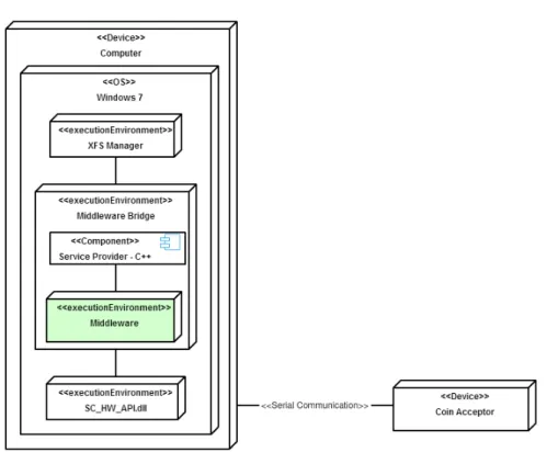
Financial applications developed with XFS can use middleware to overcome differences in plat-form implementations, and communicate with some plat-form of financial hardware. The financial hardware communicates with XFS applications through the Service Provider which is a DLL interface. Figure 2 shows the XFS software architecture with connected hardware.
Figure 2: XFS software architecture
2.4.1 Hardware - Coin acceptor
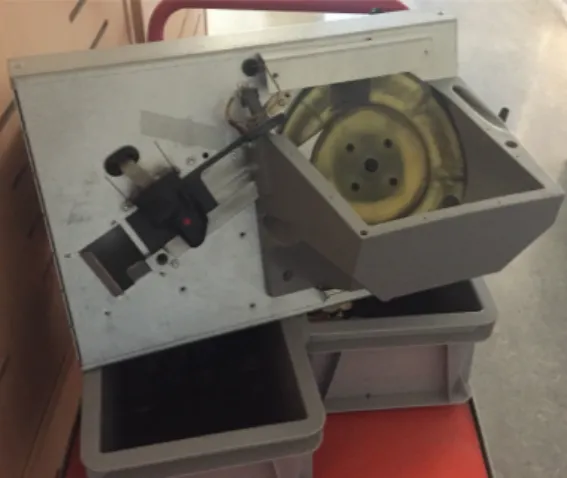
The coin acceptor at SCAN COIN valuates different coins and permits those that meet their requirements. The coin acceptor is connected to a computer using a serial connection and the computer is running SCAN COINs software. Their software registers, among other things, coin values and the amount of these values. A DLL acts as a Service Provider that helps their software to communicate with the coin acceptor. Figure 3 is a picture of the coin acceptor.
3
Related work
In this chapter, relevant articles related to our research question are reviewed. Each article is summarised and comments regarding its relevance are presented at the end. The articles were found in the IEEE database by using keywords as XML JSON, middleware "distributed systems"
pattern*, "reverse engineering" reconstruction architecture views and "client server" middleware pattern*. Articles about XML, JSON, patterns and designing middleware were selected for
deeper reading.
3.1 Mitchell J, Sanchez-Ruiz A - An architectural pattern for adaptable middleware infrastructure
This paper [7] proposes the use of a specific architectural pattern for communication and guide-lines in the beginning of software development. This is done to avoid pitfalls that could lead to large modifications of the system while implementing new middleware, at a later stage.
When implementing a communication middleware, the author recommends that the host ap-plication is bound to an interface and the interface is then bound to a middleware. Doing it this way, decouples the middleware infrastructure from the application logic and makes it less painful to introduce new bindings. A simple class diagram of the pattern placed in the system shows how the business logic is bound to the interfaces.
The author discusses the message logic between components as an important part overlooked by designers. A suggestion to move the message logic to the application so that the only thing the middleware knows about is the message, is that it is a string literal being passed. This way a new middleware only needs to know that the message is a string literal and not how the message is marshalled and un-marshalled. This approach makes the system less dependent on the middleware. The author also recommends using XML because it offers an integration environment that is loosely coupled.
The author passes XML messages in a distributed system case study with three different mid-dleware to validate how easy it is to implement different midmid-dleware with their proposed archi-tectural pattern and guidelines.
Comments
The authors idea of constructing a middleware could be investigated further. The way the pattern is summarised and presented is something that our work could use.
3.2 Y. Liang et al. - Study on Service Oriented Real-time Message Middle-ware
This paper [9] implements a service oriented real-time message middleware to overcome tightly coupled message producers and consumers in publish-subscribe pattern. The tight coupling between message producers and message consumer will directly make the service provided by the consumers unavailable if communication fails. Message middleware is considered a key component and attractive in distributed systems. Message middleware promotes a data-centric communication and connects communicating services. A looser coupling between services is achieved by being oblivious to other services it is communicating with.
According to the authors, traditional middleware solutions involve distributed publish-subscribe systems that send messages from producers to broker clusters which in turn sends the messages to consumers. This induces a tight coupling between message producers and consumers and offline consumers affect this process. To address the problems with a tight coupling the authors introduce the following solution for a new middleware.
The message consumer register themselves on the server. The registration information include topic name and service status. The message consumer needs to send a heartbeat every 30 sec-onds to maintain the registration. Software heartbeats are used to determine service liveliness. The message producer can find which message consumer that is registered and subscribed to interest services. The middleware fetches the registered services from the server and stores it locally. The message producer obtains the service from the local cache and calls the service by sending a message. Local cache guarantees availability of the services even when the server is unavailable.
To test the latency of the middleware, a stream of produced messages are received by the consumer. Each message is marked with a timestamp for indicating when the message is sent. When the message is received by the consumer, it computes the time difference. The second test calculates the amount of data the middleware is able to send each second.
The authors introduce a middleware layer that decouples producers and consumers to achieve a loose coupling and adopt a push-based message consumption model that delivers messages arriving at the message broker.
Comments
The idea of a looser coupling between the producer and the consumer is interesting when de-signing a middleware for a distributed system. By making the coupling loose, the middleware itself has great portability. Portability is an key aspect when developing a middleware be-cause it should be easy to reuse and implement in other parts of the system. The controlled experiments with latency are interesting and will be considered when designing our middleware.
3.3 Rubel P et al. - Fault Tolerant Approaches for Distributed Real-time and Embedded Systems
This paper [8] proposes a Fault Tolerance (FT) middleware that is a central design selection for mission-critical distributed real-time and embedded (DRE) systems. According to the authors, replicated servers are common in fault tolerance replication solutions but not in DRE systems. Many DRE systems use a peer-to-peer structure. The peer-to-peer structure performs client and server roles at the same time and on both sides. According to the author, this structure prohibits replicated servers.
Therefore, the following contributions in this paper are made: An approach to communicating with replicas titled Replica Communicator (RC), an approach to a self-configuring replica com-munication layer and an approach to duplicate message management to replicated clients and server, which deals with peer-to-peer interactions. This is achieved by using a Group Communi-cation System (GCS) and a lookup table. The lookup table is introduced to manage references to replicas and non-replicas.
The software is evaluated by using failure recovery time measurements from two failure sce-narios and from comparing performance from a simple client-server model running with and without the authors fault tolerant software.
Comments The idea of replicating the server and keeping track of all replicas with a lookup
table, could be of value to our middleware prototype.
3.4 Liu X, Ma L, Liu Y - A Middleware-based Implementation for Data Integration of Remote Devices
This paper [10] describes a middleware that uses Component-Oriented Programming (COP), message queuing, XML and publish-subscribe design pattern. The authors design the middle-ware as a soft-gateway that bridges upper-level softmiddle-ware with lower-level Data Transfer Units (DTU). The key part of data communication is extracted from its original holder and imple-mented in the middleware.
The middleware is composed of four modules: packet transceiver, message reader/writer, packet parser/re-packer and data forwarder. According to the author, this guarantees flexibility and robustness for the middleware. The author also recommends using XML to encapsulate parsed values.
The packet transceiver communicates with DTUs and pushes messages into a queue and the message reader/writer obtains messages from the queue. The parser/re-packer encapsulates data in XML format intended for applications and the data forwarder tags the message with a topic and uses a socket server and the publish-subscribe pattern to send messages to applica-tions that asked to receive messages with that specific topic.
The author states that because of data load, performance, security and robustness, the mid-dleware is deployed on two separate servers, which deals with data of distributed sources in parallelization.
Comments
The authors do not describe if the implementation is successful but their middleware approach with a message queue and publish-subscribe pattern could be used in our work.
3.5 Hsu K, Leu J - Improving the efficiency of presence service in IMS by JSON
This paper [29] evaluates JSON and XML in a IP multimedia subsystem (IMS). IMS is an IP architecture that delivers multimedia services. The authors adopt different open source projects to be able to implement a IMS platform based on a IMS network. This allows users to com-municate with each other via browsers supporting WebRTC. The evaluation of the message transmission time is done by having three different quantities of user on the IMS gateway and the amount of users was 50, 100 and 150.
The authors lists used hardware and shows graphs containing the test results. Tests show that encoded JSON data size is 40% smaller than XML and by using JSON in IMS, message transmission time is reduced by 40% to 60%.
Comments
The test is interesting even though it focuses on an IMS architecture. The comparison of JSON and XML is something that is valuable for our work.
4
Method
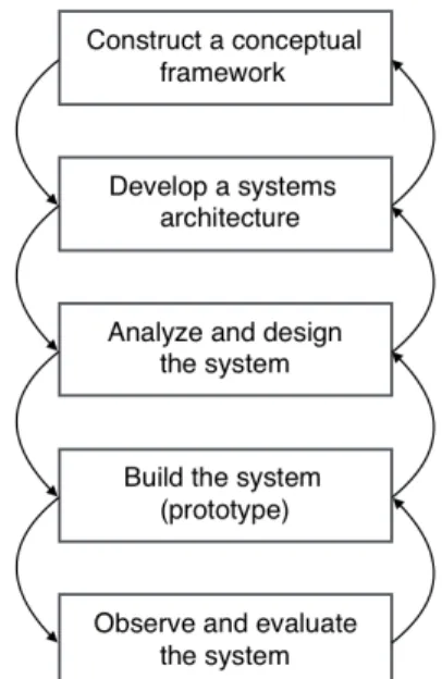
The proposed solution and prototype will be developed using a system development research process by Nunamaker, Chen and Purdin [30]. The proposed steps in the research process method in Figure 4 handles both the procedure of software engineering development and neces-sary research steps when performing software research. An iterative development ensured that all steps in the method was carried out throughout the development life cycle. Because of this, we chose to use this research method.
Figure 4: Research method by Nunamaker, Chen and Purdin
4.1 Construct a conceptual framework
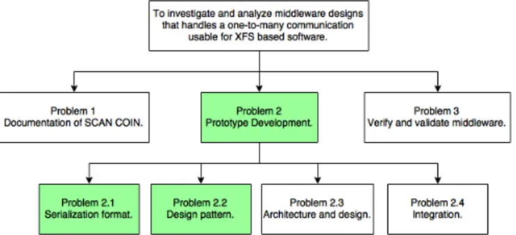
A conceptual framework is the basis of a thesis and it consists of theory building, investigation of system functionalities and requirements, stating a research question and study relevant aca-demic fields. In the first stage of the research process, the conceptual framework was important to get a clear focus of the problem and organise our software research. To do so we focused on a feasibility study which includes finding related work and compile a theoretical background that was relevant to the problem. The question and aim for this research were formulated during a meeting with representatives from SCAN COIN. The defined research aim, research question and feasibility study gives a better and clearer understanding of the development process and a direction of the continuous work.
The formulated research aim (see section 1.2) is broken down into three problems (see Fig-ure 5). The first problem (Problem 1) is to document the current system. Documentation of the software helps us to achieve a greater understanding of the software and possible solutions for our middleware prototype. The second problem (Problem 2) is to develop the middleware prototype by investigating communication protocols, serialization formats and design patterns. Also the proposed prototype needs to be evaluated before the validation and verification (Prob-lem 3).
Figure 5: Overview of problems.
Problem 1 is broken down to additional subproblems (see Figure 6). Software requirements spec-ification (Problem 1.1) is gathered for our middleware prototype. The software requirements specification consist of functional and non-functional requirements and these requirements are listed in section 5.1. Software requirements specification defines the required functionality of our middleware.[31, 32]
The second subproblem (Problem 1.2) is to analyse and reconstruct SCAN COINs software. By performing re-engineering, a reconstruction was created and it showed us where in the current software our middleware prototype needed to be implemented. The reconstruction is visualised using deployment diagram, sequence diagram and class diagram. The reconstruction of SCAN COINs software is found in section 5.2.
Figure 6: Overview of problem 1 and its subproblems. Problem 1.1 and 1.2 are investigated during this step in the research method.
4.2 Develop a systems architecture
In this stage of the research process it was important to find a design for the prototype ar-chitecture that meets the demands that were identified in section 4.1. The arar-chitecture of the prototype was influenced by several steps in the Attribute-Driven Design (ADD) method [33]. According to ADD, requirements and design constraints needs to be defined by the stakeholder and they were defined in section 5.1. The next step in ADD was to identify and choose an ele-ment in the software system, or the entire system, to decompose and this was done by extracting information about SCAN COINs software system from the reconstruction in section 5.2. Also, potential patterns were identified based on the architectural drivers, the requirements, and the extracted information.
Figure 7: Overview of problem 2 and its subproblems. Problem 2.1 and 2.2 are investigated during this step in the research method.
The first subproblem (Problem 2.1) is to find a serialization format and communication tech-nique for passing messages between the clients and server. Serialization formats are well doc-umented and our choice of serialization format is based on results of previous research (see section 3.5). The choice between pipes and sockets is based on a performance comparison (see test case TC3 and test case TC4).
The second subproblem is to find design patterns that we could use to solve our one-to-many problem. Patterns regarding distributed infrastructure systems were considered when perform-ing a literature study. The design patterns were selected (see section 5.3.2) by comparing common distributed patterns and common demultiplexing patterns [11] with the identified soft-ware architecture from the reconstruction (see section 5.2) of SCAN COINs current softsoft-ware system.
4.3 Analyse and design the system
In this stage (see Figure 8), the architecture was defined and the middleware was designed to fulfil the requirements (see section 5.1) using the serialization format and design pattern (see section 5.3.1 and 5.3.2) that was brought forward in earlier stages of the research process. Dia-grams for the new middleware were drawn, class diaDia-grams describes the architectural design of the middleware and sequence diagrams describes the internal communication (see section 5.3.3).
Figure 8: Overview of problem 2 and its subproblem. Problem 2.3 is investigated during this step in the research method.
4.4 Build the prototype
During this stage (see Figure 9), the middleware was constructed and implemented in SCAN COINs software (Problem 2.4). With the result from the reconstruction (see section 5.2) and our proposed middleware solution (see section 5.3.1, 5.3.2 and 5.3.3) we constructed and imple-mented the middleware in SCAN COINs already existing software. The result of the integration process is to be found in section 5.3.4 where a new software architecture view, deployment di-agram, sequence and class diagrams describe and visualise the middleware integrated into the current system.
Figure 9: Overview of problem 2 and its subproblem. Problem 2.4 is investigated during this step in the research method.
4.5 Observe and evaluate the system
In this final stage (see Figure 10), the reconstruction, prototype and test cases are evaluated (see section 5.2.1 and 5.3.5) and also verified against the requirements (see section 5.1) using the results from the evaluation. To verify the ability of handling concurrency, test cases (see section 5.5) were performed where two or more clients were connected and manipulated the hardware. To verify interoperability, the prototype is created as similar as possible to the original software, so that an implementation in SCAN COINs software should be accomplished with as few alterations as possible. To verify performance, the communication process is compared, analysed and evaluated (see section 5.3.1, section 5.3.5 and section 5.5.3).
Figure 10: Overview of problem 3. This problem is investigated during this step in the research method.
5
Results and Evaluation
This chapter presents the results from the development process. Software requirements and reconstruction of SCAN COINs software is a preamble to the prototype development and it determines the architecture, design and integration of the prototype. Controlled experiments, test cases, are used to evaluate the prototype.
5.1 Software Requirements Specification
Functional requirements describe what the middleware is supposed to do, in our case what it is supposed to do in SCAN COINs software. Non-functional requirements describe qualities of the middleware and these requirements also depict limitations for the developer [32]. The following requirements are identified from discussions with SCAN COIN.
Functional Requirements:
1 Many applications must be able to connect to a single hardware device and share the hardware access.
2 The middleware implementation must be able to lock out other instances/applications.
3 The middleware implementation should be based on design patterns.
4 The client-server IPC-connection must communicate with either JSON or XML using Pipes or Sockets.
Non-Functional Requirements:
5 The middleware design must be interoperable and functional with other hardware devices with minor modifications. Minor modifications should be accomplished within one days work.
6 The communication between client-server must ensure performance and offer better value compared to other formats/techniques. Better value is translated into smaller data size and lower transmission time.
7 The XFS platform is based on Windows OS platform.
8 The prototype must be written in the C++ programming language for better platform compatibility with XFS based software.
5.2 Reconstruction
SCAN COINs current implementation uses a bridge between the XFS Manager and the coin acceptor driver. The name of the bridge is X2J and the bridge is responsible for the communi-cation between the XFS manager and the hardware.
The first step is to get an overview of the system, and this is achieved by using a deployment diagram. In Figure 11 the physical nodes and artifacts of the system are visualised.
Figure 11: Deployment diagram of the software system before middleware implementation.
The deployment diagram in Figure 11 contains two physical nodes, the computer and the coin acceptor. SCAN COINs software is currently divided into three layers: XFS Manager, X2J bridge and Java XFS drivers. The X2J bridge contains the Service Provider (see section 2.4) and the X2J server that send local messages using sockets, which can be seen in Figure 11. The Java XFS drivers are to be removed and a new DLL containing hardware drivers for the coin acceptor is already in development. Instead of the X2J bridge, a new middleware solution between the Service Provider and the new DLL needs to be developed and implemented. In Figure 12, a deployment diagram shows the location of the prospective middleware between the Service Provider and the new SC_HW_API.dll, developed by SCAN COIN.
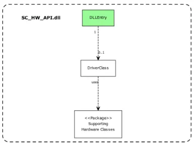
The class diagram in Figure 13 describes the SC_HW_API.dll. The green highlighted DL-LEntry class is specified as the entry-point to the DLL when loading SC_HW_API.dll and it is through this entry-point that the coin acceptor will be controlled. DLLEntry is the only class that is of interest in the middleware. DLLEntry initiates DriverClass which in turn initiates other classes and its corresponding threads for all hardware in the coin acceptor. The middle-ware prototype must send commands through DLLEntry to DriverClass, which in turn sends commands further towards the hardware to control the coin acceptor.
There are many commands and functions that control the coin acceptor and four functions are SCOpen, SCClose, SCAsyncExecute and SCAsyncGetInfo. For extended functionality and reuse of code, different commands are passed to SCAsyncExcute and SCAsyncGetInfo as pa-rameters. Sequence diagrams that describe the internal communication for Open CAM, Close CAM, Start Coin Acceptor, Stop Coin Acceptor and Status commands are displayed in Figure 19, 21, 23, 25 and 27 (see Appendix A). These sequence diagrams show how the coin acceptor is controlled by the commands.
Figure 13: An incomplete class diagram that displays with green color the part of SC_AW_API.dll that is of interest.
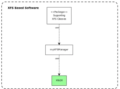
After the reconstruction of SCAN COINs XFS manager, it was identified that every Service Provider has access to shared communication classes. A Service Provider uses myXFSManager
to send messages through XfsDll to the hardware and the XfsDll class becomes an exit point from the Service Provider when it loads an outside DLL for further communication in the obsolete X2J Bridge (see Figure 11). Therefore, the green highlighted XfsDll class in Figure 14 below, is the only class of interest and it needs to be rewritten/replaced so that it instead loads the proposed middleware prototype. Sequence diagrams for Open CAM, Close CAM, Start Coin Acceptor, Stop Coin Acceptor and Status commands are displayed in Figure 18, 20, 22, 24 and 26 (see Appendix A).
Figure 14: An incomplete class diagram that displays with green color the XFS based software part of interest.
5.2.1 Evaluation of Reconstruction
Each manufacturer defines their own logic behind the API and SPI in the XFS standard, ac-cording to their needs and requirements. This creates differences between each XFS based software. A solution to this problem is to gather information about the software system before the development process. The information is gathered from a reconstruction.
A reconstruction using class and deployment diagrams gave enough structural information for deciding where our middleware prototype is supposed to be implemented. Sequence diagrams describe the interaction between components in the software. The information from the dia-grams combined with the stakeholders requirements ease the choice of a suitable design pattern for our prototype. A problem during the reconstruction was that due to high complexity in SCAN COINs legacy XFS based software, we chose to limit the reconstruction. This limita-tion was sufficient for a proof-of-concept but with increased complexity during the development process, uncertainties arose regarding the information from the reconstruction. A new recon-struction needs to be considered before a full integration.
5.3 Prototype development
5.3.1 Serialization format
When analysing the research results for text-based communication in section 3.5 and comparing it with the non-functional requirements in section 5.1, it showed that JSON is the better option for the middleware communication. Two similar comparisons confirmed JSON to be more efficient than XML [34, 35]. The comparison between section 5.1 and section 3.5 follows below:
• The text-based communication between client-server must ensure performance and offer better value compared to other formats. Better value is translated into smaller data size and lower transmission time (see section 5.1).
• Tests by Hsu K and Leu J show that encoded JSON data size is 40% smaller than XML and by using JSON in IMS, message transmission time is reduced by 40% to 60% (see section 3.5).
5.3.2 Design pattern
The design patterns for the prototype are based on Reactor and Broker [11]. This decision was based on the software problem to connect many applications/clients to a listening server in a one-to-many relationship and to communicate with the hardware in a one-to-one relationship. A one-to-one relationship between server and hardware is necessary because the hardware can only handle one request at a time.
The Broker pattern separates and encapsulates communication details from applications. This reduces the coupling between a component and its communication. Broker also defines compo-nents that invoke location independent method services. This means that a client can invoke remote methods on the server as if they were locally connected. Broker was first used in the Common Object Request Broker Architecture (CORBA) from 1992 by Object Management Group (OMG), before the pattern was abstracted and brought forward by Frank Buschmann, Regine Meunier, Hans Rohnert, Peter Sommerlad and Michael Stal in 1996 [6].
The Reactor pattern simultaneously waits on multiple sources and when a service request oc-curs, it demultiplexes and dispatches the request one request at a time. This means that the processing of requests are done sequentially and synchronous. Reactor reduces the coupling between components by handling multiple client requests. The Reactor pattern was brought forward by Douglas C. Schmidt in 1994 [6] and the pattern was commonly used in event-driven servers, such as distributed logging services [36].
5.3.3 Architecture and design
The architecture and design for the middleware prototype follows the chosen design patterns. The server must handle multiple connecting clients in a one-to-many relationship. When a client message is ready, the server must pick up the message and execute the client request from start to finish. The client must invoke server functions to the hardware via JSON messages as if the client was connected directly to the hardware. The server must respond directly to the client before handling the next client message in a synchronous one-to-one relationship.
The choice of using a pipe technique between client and server was based on a performance test between sockets and pipes (see test case TC3 and test case TC4) and test case TC3 showed satisfactory results for the pipe communication. The pipe server is open to multiple read and
write operations on different pipe instances and the pipe server decides the number of simulta-neous client instances. Multiple connecting clients are handled with a wait for multiple objects function [37, 38]. However, a First-In-First-Out (FIFO) queue is implemented towards the hardware and client requests are queued in the pipe server until the current client is finished. This approach creates a one-to-many relationship between clients and server and a one-to-one relationship between server and hardware.
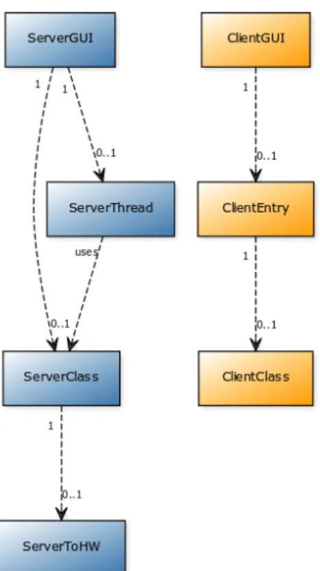
A simple ClientGUI class was created instead of modifying SCAN COINs software and a text window and buttons with basic commands were implemented. ClientGUI utilises a load li-brary function to load the client-DLL and this is the same function used in SCAN COINs software. The client-DLL contains the ClientEntry class and the ClientClass. The ClientEntry class contains the same function names as SCAN COINs software, to simplify integration. The ClientClass connects to a listening pipe server and sends JSON hardware commands from the ClientGUI. This approach separates and encapsulates the communication from the ClientGUI.
A ServerGUI class was created with a simple start and stop command, which controls the server. The server is started in the ServerThread class because the server communication is in an infinite loop. By running the server in a thread, ServerGUI can stop the server if necessary. The ServerClass is a class that listens for multiple connecting pipe clients and it multiplexes and demultiplexes JSON messages sequentially using a FIFO queue. ServerClass dispatches JSON responses to the client and commands to the ServerToHW class, which communicates with the hardware. This approach separates and encapsulates the client communication from ServerToHW and the hardware communication from ServerClass. Figure 15 shows the class diagram for the middleware prototype.
5.3.4 Integration
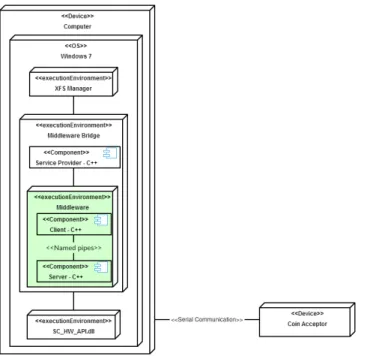
By connecting the middleware to SCAN COINs hardware DLL entry point seen in section 5.2, the prototype has the ability to control the coin acceptor. After a reconstruction of the software system, an exit point from XFS Manager was discovered and by connecting to the exit point in section 5.2, the middleware prototype has the ability to communicate with XFS Manager. Figure 16 shows the implementation of the middleware in Figure 2 with green colour.
Figure 16: Software architecture with implemented middleware.
Figure 17 describes a conceptual integration of the middleware prototype in SCAN COINs software system using a deployment diagram. The middleware prototype is placed between the Service Provider and SC_HW_API.dll, which is the DLL for controlling the coin acceptor. The middleware binds XFS Manager to the coin acceptor and redirects function calls from XFS Manager to SC_HW_API.dll. The communication only takes place through the exit and entry points and this keeps the different parts encapsulated from each other.
In the integration process, the middleware entry and exit point was localised after a recon-struction of SCAN COINs software. The server in the middleware prototype is responsible for connecting to the coin acceptor. This integration is done by loading the DLLEntry class and utilising the DLL functions to access hardware functions. This is visualised in Figure 18 with a class diagram that combines the class diagram from Figure 13 called SC_HW_API.dll and the class diagram for the server in Figure 15.
The second class diagram in Figure 18 describes a conceptual integration of SCAN COINs software with the middleware prototype. The class diagram describes how XfsDll loads the DLL for ClientEntry and utilises the DLL functions to send further commands towards the server through ClientClass. This integration is done by combining XFS software from Figure 14 and the client in Figure 15. Figure 29-32 in appendix A shows sequence diagrams through the middleware to the hardware.
Figure 18: Two class diagrams describing the integration of the server (Left) and client (Right) to the already existing software.
5.3.5 Evaluation of Prototype
Both synchronous and asynchronous solutions are allowed in XFS based software and this cre-ates uncertainties of which solution is the most suitable. This problem was solved by focusing on the requirements (see section 5.1). Requirement 1 and 2 are important to achieve a one-to-many solution towards the hardware but requirement 3 and 4 are techniques that simplified the development and possibly not as important to other developers. The non-functional require-ments are SCAN COIN specific and possibly not as important to other developers.
An assumption based on the software problem was made that a synchronous solution would suffice to achieve requirement 1 and 2. The results in test case TC7 shows that requirement 1 and 2 was achievable with a synchronous solution. The choice of using the Reactor pattern was based on the hardware limitation, that only one client request can be handled at a time and therefore a synchronous one-to-one relationship, or FIFO queue, was established between the server and hardware. Also the Broker and Reactor pattern were used, so that many clients could connect to a server and send request to the hardware in a decoupled one-to-many relationship. The client-server communication used JSON messages over a pipe connection. Section 5.5 shows extensive prototype testing to verify our results and test case TC13 proves that simultaneous communication was achievable.
The one-to-many problem, was solved with a wait for multiple objects function in the pipe server. The problem with locking out applications from simultaneous hardware access was solved by implementing a FIFO queue towards the hardware and test case TC8 shows that server responses are sent after the hardware is finished. A switch from sockets to pipes de-creases client-server latency (see analysis of test case TC3 and test case TC4 in section 5.5.3) and passing messages with JSON is more efficient than XML (see section 5.3.1).
By adding increased complexity in the server, consequences of the FIFO queue are delays in the software system because our synchronous solution waits for server responses. These responses are sent after the hardware and the communication DLL callbacks are finished. However, the callback waits are stable and have minimal user impact (see test case TC9) and some delays are inevitable. The start command has a delay under one second and this is perceived as fast when operating the hardware. During open or close commands, no other command can be managed and a delay becomes necessary because the hardware is inaccessible during these operations. There is an uncertainty in the design to what happens with the callback if the callback wait and timeout ends at the same time (see analysis of adding callback handling in section 5.5.3).
The prototype is a proof-of-concept that a one-to-many relationship is achievable in SCAN COINs software. Therefore all commands were not implemented and tested and it is possible that there are other commands with delays that have a negative impact on the system. The limited prototype implementation was sufficient to solve our stakeholders problem and answer our research question but increased complexity, as callbacks, added problems to our solution. With further development, these problems need to be addressed.
5.4 Comparison with related work
According to Mitchell and Sanchez-Ruiz [7], the host and target interact with the middleware using an interface that separates the application logic from the middleware and to achieve de-coupling of data, a XML string should be passed as a parameter in and out of the middleware. We were first inspired by this solution but we were restricted by SCAN COINs software and their
parameters are numbers. Because of this, our solution built JSON strings from the parameter number inside the middleware and the strings were passed between the client and server. This decision helps with implementation in XFS based software but portability and interoperability with other environments need more work.
Rubel P et al. [8] handle communication with replicated clients and server by using a Fault Tolerance middleware. Their middleware replicates clients and server in a peer-to-peer archi-tecture, where both sides act as client and server in an environment that prohibits replicates. Our solution did not have to use replicated components to overcome the one-to-one hardware access. Instead, our middleware is a less complex pipe communicating one-to-many client-server that produced satisfactory results (see test case TC13).
Liang et al. [9] implemented a publish-subscribe pattern to achieve a loose coupling between message producers and consumers. Liu X, Ma L and Liu Y [10] also implemented the publish-subscribe pattern. The middleware by Liu X, Ma L and Liu Y pushes messages into a queue and then fetches a message from the queue before turning it into a XML message with a topic. The messages are published and applications that subscribe to the specific topic gets a copy of the message. The middleware by Liang et al. involves a message consumer that registers a topic and service on the server. The message producer searches for subscribing consumers and calls the registered service in the server. These solutions were considered as possible alternatives, but synchronous messaging was less complex to start with. With asynchronous messaging, it would be necessary with semaphores that signals and locks the hardware access from other clients until the hardware is finished. The Reactor pattern is less complex to implement when each client is handled sequentially and it fits the one-to-one hardware limitation. However, the loss of asynchronous messaging in the Reactor pattern could create performance issues if all processes are not equal in time and an asynchronous pattern could be a better solution when handling callbacks to clients in our solution.
Both Mitchell and Sanchez-Ruiz [7] and Liu X, Ma L and Liu Y [10] suggested that XML should be used as text-based communication. Two identical comparisons as section 5.3.1, con-sidered JSON to be more efficient than XML. The first comparison used resource-constrained embedded devices with low data rate. In that experiment, JSON had a lower request time, higher average byte/sec, lower size and fewer frames [34]. The second comparison found that with lightweight applications, JSON can save calculation resources, reduce network transmis-sion time and speedup network transmistransmis-sion speeds [35]. These two comparisons creates more validity to the research results in 5.3.1.
5.5 Controlled Experiments
Controlled experiments were used to verify the functional and non-functional requirements (see 5.1). The results from controlled experiments were measurable because all of the experimental variables were controlled. Variables were manipulated until the result matched the expected result and the test was then labelled as passed. If the test was for a requirement, the requirement was verified when the test passes. All tests were performed in SCAN COINs IDE called RAD Studio [39]. Results, comments and an analysis is found below. Some test cases in Table 1 verify requirements and some were development iterations toward requirements. When a test passed in the iterative development, all previous tests were also considered to have passed. Table 2 shows comments regarding the test and if it passed or failed. See Appendix B for complete test cases.
5.5.1 Test Cases
ID Requirement Title
TC1 4 Send a message between a pipe client and server.
TC2 4 Send a message between a Windows socket client and server.
TC3 6 Test the performance of a pipe client and server.
TC4 6 Test the performance of a Windows socket client and server.
TC5 Send open command from a server GUI to the hardware.
TC6 Send start and stop commands from a client GUI to the hardware.
TC7 1 Send start and close commands from different client GUIs to the hardware.
TC8 2 Send close and start commands from different client GUIs to the hardware.
TC9 Determine the impact of callbacks.
TC10 Send open command and receive a callback from the hard-ware DLL.
TC11 Send status command and receive a callback from the hard-ware DLL.
TC12 Send start and stop commands and receive callbacks from the hardware DLL for each command.
TC13 1 Send open, start and status commands from different client GUIs and wait for either a callback or a timeout.
5.5.2 Results
ID Result Comment
TC1 PASS The client text window displayed: "Default server response".
TC2 PASS The client text window displayed: "Default server response".
TC3 PASS The client text window displayed: "10/10 messages passed in 0 sec",
"100/100 messages passed in 0.006 sec", "1000/1000 messages passed in 0.043 sec" and "10000/10000 messages passed in 0.196 sec".
TC4 PASS The client text window displayed: "10/10 messages passed in 0.823
sec", "100/100 messages passed in 2.601 sec", "1000/1000 messages passed in 18.046 sec" and "10000/10000 messages passed in 259.492 sec".
TC5 PASS The hardware clicked two times and a 0 was returned.
TC6 PASS The hardware started to rotate and sort coins. The stop command stopped the hardware. A 0 was returned.
TC7 PASS The hardware started to rotate and sort coins when client 1 sent a start command and it stopped when client 2 sent a stop command. A 0 was return by both commands.
TC8 PASS The hardware opened when client 1 sent an open command, closed when client 2 sent a close command and returned an error to the start command from client 1 after the close command finished. A 0 was returned by both open and close and 1 was returned by start.
TC9 PASS The client text window displayed: "Open wait: 3.68 sec", "Start wait:
0.86 sec", "Stop wait: 0 sec" and "Status wait: 0 sec".
TC10 PASS The hardware opened when the client sent an open command and an event callback was displayed on the text window.
TC11 PASS A status command was sent by the client and an info callback was displayed on the text window.
TC12 PASS The hardware started to rotate and sort coins when the client sent a start command and an execute callback was displayed on the text window. When the client sent a stop command, the hardware stopped and an execute callback was displayed on the text window.
TC13 PASS The hardware opened when client 1 sent an open command and the callback was displayed. The hardware started to rotate and sort coins when client 1 sent a start command and the callback was displayed. A hardware status callback was displayed when client 2 sent a status command.
5.5.3 Analysis of Test Cases Requirement 4 - Pipes or sockets
The first test was about finding out if both sockets and pipes could be used when sending messages locally between different processes. This is shown with test case TC1 and test case TC2. Both techniques can also send messages between different computers, but this is not of importance because the communication between client and server is on the same computer.
Requirement 6 - Performance of pipes and sockets
The next step was to test the performance of pipes and sockets, before moving forward with one technique. Test case TC3 and test case TC4 showed that both sockets and pipes delivered all messages without loss. This was verified by iterating through every client and server message and matching all letters with the original word, which was hard coded only as comparison ref-erence. A successful delivery increased a counter. This comparison introduced a delay, but by using identical code for both sockets and pipes, the delay was also identical for both techniques and therefore can be neglected. This means that the results for each technique were actually lower but the importance of the test was to compare the ratio between them.
The time taken for sending 10 pipe messages between processes was not measurable and the time taken for 10000 socket messages fluctuated up and down a great deal, so 100 and 1000 messages are analysed. The ratio between 100 socket and pipes messages are: 2.601sec0.006sec ≈ 434. The ratio between 1000 socket and pipes messages are: 18.046sec0.043sec ≈ 420. These calculations show that pipes send local messages over 400 times faster than sockets and therefore the pipe connection decreases latency compared to the socket connection.
Building the client-server
After choosing the pipe technique, a temporary server GUI with more logic was utilised before adding a client. In test case TC5, it was possible to test hardware functions before integrating the logic in a client, which is shown in test case TC6. Test case TC6 is based on the pipe solution used in test case TC3. This solution produced satisfactory results and was therefore used in further development.
Requirement 1 - One-to-many relationship
This test was about the stakeholders main problem; a one-to-many relationship. Test case TC7 follows test case TC6 and two client GUIs are started. Every client GUI loads its own client-DLL with its own pipe communication to the same pipe server. Every pipe client is able to send commands to the pipe server, every command is dispatched to the hardware and the server responds to every client command using a one-to-many relationship. Error handling is implemented by returning numbers to indicate if an operation was successful. A zero means everything was OK and one means an error occurred.
Requirement 2 - Locking out applications
Requirement 2 was about locking out applications. Test case TC8 utilises the close command, which is a special command because it takes approximately 15 seconds for the hardware to accomplish. This means that no other client can communicate with the hardware until it is finished. All other test case commands are handled fast, so the close command is an opportunity
to test the queueing of client messages when the hardware is occupied. Queued client messages are handled with the implemented FIFO queue and the next client message is dispatched when the current client is finished and the FIFO queue locks out other applications.
Determine the impact of callbacks
This test was about increasing complexity and waiting for callbacks to determine their impact on the middleware. The callbacks of an open command takes approximately 3.68 seconds to complete, a start command takes approximately 0.86 seconds and both stop and status com-mands are handled instantaneously. These results were stable every test iteration. Callbacks are sent asynchronous from the hardware DLL and the open callback comes after the hardware has opened and the start callback comes after the hardware is set to an active mode.
In order to handle these callbacks synchronously and send them as responses to the client, the server must wait the amount of time previously mentioned. But it is unnecessary to always wait the same amount of time and for stop and status commands to wait, because they were handled instantaneously. A flag should be set when the callback is finished but if a callback disappears, a timeout must also be set so that the wait is not infinite. The amount of time needed for the timeout should be more than the results mentioned above.
Adding callback handling
The solution to wait for callbacks was successful and the timeout made sure that the wait is not infinite, as a safety precaution, in case a callback is lost. If the timeout ends, a response without a callback is sent. The wait flag is versatile, and can be set to false for commands without callbacks. By doing this, no unnecessary timeout wait is created. Test case TC9 to test case TC11 passed and all callbacks were displayed in the client text window.
Requirement 1 - One-to-many relationship with callbacks
The final test was about verifying that callbacks could be handled in a one-to-many relationship. The status callback was successfully received and displayed on a second client text window while the hardware was operated from another client.