Thesis no: XXXX-20XX-XX
Faculty of Engineering
Department of Applied Signal Processing Blekinge Institute of Technology SE-371 79 Karlskrona Sweden
Performance Analysis of a MIMO
Cognitive Cooperative Radio Network with
Multiple AF Relays
i This thesis is submitted to the Faculty of Engineering at Blekinge Institute of Technology in partial fulfillment of the requirements for the degree of Masters in Electrical Engineering with Emphasis in Radio Communications.
Contact Information: Authors:
Advaita
j.advaita@gmail.com Mani Meghala Gali
manimeghala8@gmail.com Supervisor:
Dr. Thi My Chinh Chu Faculty of Computing
Department of Communication Systems thi.my.chinh.chu@bth.se
Examiner:
Prof. Hans-Jürgen Zepernick Faculty of Computing
Department of Communication Systems hans-jurgen.zepernick@bth.se
iii
A
BSTRACT
With the rapid growth of wireless communications, the demand for the various multimedia services is increasing day by day leading to a deficit in the frequency spectrum resources. To overcome this problem, the concept of cognitive radio technology has been proposed which allows the unlicensed secondary user (SU) to access the licensed spectrum of the primary user (PU), thus improving the spectrum utilization. Cooperative communications is another emerging technology which is capable of overcoming many limitations in wireless systems by increasing reliability and coverage. The transmit and receive diversity techniques such as orthogonal space–time block codes (OSTBCs) and selection combining (SC) in multiple-input multiple-output (MIMO) cognitive amplify and forward relay networks help to reduce the effects of fading, increase reliability and extend radio coverage.
In this thesis, we consider a MIMO cognitive cooperative radio network (CCRN) with multiple relays. The protocol used at the relays is an amplify and forward protocol. At the receiver, the SC technique is applied to combine the signals. Analytical expressions for the probability density function (PDF) and cumulative distribution function (CDF) of the signal-to-noise ratio (SNR) are derived. On this basis, the performance in terms of outage probability is obtained. Mathematica has been used to generate numerical results from the analytical expressions. The system model is simulated in MATLAB to verify the numerical results. The performance analysis of the system model is hence done in terms of outage probability.
Keywords: Cognitive radio, Cooperative communications, Space time coding, MIMO systems, Outage probability
iv
ACKNOWLEDGEMENTS
First of all, we would like to express our gratitude to our supervisor Dr. Thi My Chinh Chu for her enormous support throughout the thesis. Our thesis would have not been possible without her. We are forever indebted to our examiner Prof. Hans-Jürgen Zepernick for his valuable guidance. It is a privilege to work with him.
We are very grateful to our families and friends for their constant encouragement in all our endeavors in life. We are obliged to have each other as team members and are thankful to each other for all the support during the thesis.
Above all, we thank the almighty for always showering his blessings and love upon us.
ADVAITA MANI MEGHALA GALI
v
C
ONTENTS
ABSTRACT ... III ACKNOWLEDGEMENTS ...IV CONTENTS... V 1 INTRODUCTION ... 8 1.1 MOTIVATION ... 8 1.2 RELATED WORKS ... 8 1.3 RESEARCH QUESTIONS... 101.4 MAIN CONTRIBUTIONS OF THIS THESIS ... 10
1.5 OUTLINE OF THE THESIS ... 11
2 FUNDAMENTALS OF ADVANCED RADIO COMMUNICATIONS ... 12
2.1 COGNITIVE RADIO TECHNOLOGY ... 12
2.2 COOPERATIVE COMMUNICATIONS ... 14
2.3 FUNDAMENTALS OF MIMOSYSTEMS AND SPACE-TIME CODING ... 16
2.4 WIRELESS CHANNELS AND FADING ... 18
3 PERFORMANCE ANALYSIS IN TERMS OF OUTAGE PROBABILITY ... 20
3.1 SYSTEM MODEL ... 20
3.2 DEFINITION OF OUTAGE PROBABILITY ... 21
3.3 CALCULATION OF SNR ... 22
3.3.1 First hop ... 22
3.3.2 Second hop ... 23
3.4 DERIVATION OF CDF OF SNR ... 26
3.5 EXPRESSION OF OUTAGE PROBABILITY ... 31
4 NUMERICAL AND SIMULATION RESULTS... 32
4.1 SCENARIO 1:VARYING THE NUMBER OF RELAYS ... 32
4.2 SCENARIO 2:VARYING THE NUMBER OF ANTENNAS ... 33
4.3 SCENARIO 3:VARYING THE FADING SEVERITY PARAMETER ... 35
4.4 SCENARIO 4:VARYING THE DISTANCE ... 36
5 CONCLUSION AND FUTURE WORKS ... 39
vi
ABBREVIATIONS
AF Amplify-and-Forward
CCRN Cognitive Cooperative Radio Network
CDF Cumulative Distribution Function
CLPC Closed Loop Power Control
CR Cognitive Radio
CSI Channel State Information
IF Intermediate Frequency
MIMO Multiple-Input Multiple-Output
NOAF Non-Orthogonal Amplify and Forward
OAF Orthogonal Amplify and Forward
OP Outage Probability
OSTBC Orthogonal Space-Time Block Code
PDF Probability Density Function
PU Primary User
RF Radio Frequency
RV Random Variable
SC Selection Combining
SER Symbol Error Rate
SNR Signal-to-Noise Ratio SU SINR PURX SUTX Secondary User Signal-to-Interference-Plus-Noise Ratio
Primary User Receiver Secondary User Transmitter
vii SURX OF BW EF DF SUR
Secondary User Receiver Operating Frequency Bandwidth
Estimate and Forward Decode and Forward Secondary User Relay
8
1
I
NTRODUCTION
1.1 Motivation
The world has witnessed a rapid growth and development in wireless communications during the last few decades. This has led to an increase in the number of users and demand for higher data rates and services. Cognitive radio (CR) and cooperative communications are two promising technologies which have proved to improve spectrum utilization and reliability. The CR technology allows the spectrum to be shared among licensed users called primary users (PUs) and unlicensed users called secondary users (SUs). The secondary users are also known as cognitive users. Cooperative communications, on the other hand, provides an efficient energy transmission to increase the coverage area of the wireless networks. The basic idea behind cooperative transmission is that in a wireless environment, the signal transmitted by a source to a destination node is also received by other terminals called relays. The relays process and retransmit the signals which they receive. The destination then combines the signals coming from the source and the relays. This creates spatial diversity by taking advantage of the multiple receptions of the same data at the various terminals from different transmission paths. These factors are the motivation of this thesis. In this chapter, the motivation of this thesis, the related works done in this domain and the main contributions are discussed.
1.2 Related Works
The topic of multiple-input multiple-output (MIMO) cognitive and cooperative relay networks provides a great scope for research. The work reported in [1], provides information about the important aspects of the cognitive and cooperative technologies such as spectrum sensing techniques, matched filter detection, energy detection, cyclo-stationary detection, wavelet detection etc. It deals with spectrum sharing and most importantly about cognitive space–time–frequency coding technique that can opportunistically adjust its coding structure by adapting itself to the dynamic spectrum environment. In [2], the joint relay selection and power allocation to maximize system throughput with limited interference to licensed users in CR systems has been investigated. An optimal approach based on the dual method is proposed and a suboptimal approach to reduce complexity while maintaining reasonable performance has been discussed. In [3], outage probability of cognitive relay networks with
9 cooperation between secondary users based on the underlay approach, while considering the interference constraint on the PU, has been calculated.
In [4], the exact outage probability (OP) of cognitive dual-hop relay networks equipped with a single amplify-and-forward (AF) relay and a selection combining (SC) receiver at the destination is derived under spectrum sharing constraint on a primary user. In [5], a power control algorithm incorporating distributed beamforming via multi-relay structure with underlay cognitive radio architecture is proposed. In the underlay approach, the secondary transmission is allowed to coexist along with the primary transmission.
In [6], space–time block coding is introduced for communication over Rayleigh fading channels using multiple transmit antennas. Here, data is encoded using a space–time block code and the encoded data is split into n streams which are simultaneously transmitted using n transmit antennas. The received signal at each receive antenna is a linear superposition of the n transmitted signals perturbed by noise. The paper uses orthogonal space–time block codes (OSTBCs) to achieve the maximum diversity order for a given number of transmit and receive antennas subject to the constraint of having a simple decoding algorithm. It is a powerful approach to combat the effects of fading, increase capacity and coverage.
In [7], it has been shown that the maximum diversity order can be achieved for decouple and forward relay networks with OSTBC transmission. In [8], symbol error rate (SER) and outage performance analysis is done for AF cooperative relay networks employing transmit antenna diversity with OSTBCs, and multiple antennas are equipped at the transmitter over a flat Rayleigh fading channel. In [9], the performance of MIMO dual-hop AF relay systems using OSTBCs over arbitrarily correlated Nakagami-m fading channels is analyzed.
In [10], the spectrum-sharing problem of a basic cognitive network consisting of a PU link and SU link is studied and a spectrum-sharing scheme is proposed in which transmission diversity of the primary user is formed by the secondary user actively acting as its cooperative relaying through OSTBC. In [11], the performance of MIMO cognitive AF relay networks using OSTBC over independent Nakagami-m fading is analyzed. A lot of further research has been done in these areas. However
,
this thesis aims at analyzing performance of MIMO10 cognitive AF multiple relay networks with OSTBC for SC with multiple relays and multiple antennas at PU, secondary transmitter (SUTX), relays and secondary receiver (SURX).
1.3 Research Questions
A lot of research has been done in the areas of Cognitive cooperative radio networks (CCRNs), MIMO systems and OSTBC transmissions. However, work in this area is limited on the performance when multiple relays and antennas are considered at PU, SUTX, relays and
SURX with OSTBC transmission at SUTX. Hence, the scope of this thesis is extended to
address the following research questions:
x Does an analytical expression for the probability density function (PDF) of total SNR of the considered CCRN exist?
x Does an analytical expression for the cumulative distribution function (CDF) of total SNR of the system exist?
x Does an analytical expression for the OP of the system exists?
x How does a change in fading severity effect the outage performance of the system? x How does a change in the number of relays effect the outage performance of the
system?
1.4 Main Contributions of this Thesis
In [11], the performance of MIMO cognitive AF relay networks using OSTBC over independent Nakagami-m fading is analyzed. The Nakagami-m distribution is always advantageous compared to other models because it is a generalized distribution which can model different fading environments. It has greater flexibility and accuracy in matching some experimental data than the Rayleigh, lognormal or Rician distributions. Our thesis is an extension of the work done in [11]. We have incorporated multiple antennas at PU, SUTX,
relays and SURX along with multiple relays while considering the interference constraints
from the PU. The main contributions of this thesis are mentioned below:
x Derivation of the total SNR which includes SNRs from direct link, first hop and second hop.
x Derivation of an analytical expression for the PDF and CDF of total instantaneous SNR.
x Derivation of an analytical expression for the OP of the system. x Simulation of the system model in MATLAB.
11 x Numerical analysis is performed and is compared with simulation results.
x Study of the effect of varying fading severity, number of relays, number of antennas, and distance on the outage performance.
1.5 Outline of the Thesis
The remaining of this thesis is organized as follows. Chapter 2 deals with the fundamentals of cognitive radio networks, cooperative communications, MIMO systems, OSTBC transmissions and fading. Chapter 3 presents the system model, derivations of SNR, CDF of SNR and the expression for OP. Chapter 4 provides the numerical results, obtained graphs and analyses. Specifically, the outage probability versus signal-to-noise ratio (SNR) plots are discussed. Finally, Chapter 5 concludes the thesis.
12
2
F
UNDAMENTALS OF
A
DVANCED
R
ADIO
C
OMMUNICATIONS
This chapter takes up the fundamentals of advanced radio communications. Section 2.1 is about the basics of CR technology. Section 2.2 handles basics of cooperative communications. Section 2.3 incorporates the MIMO systems and space-time coding techniques and Section 2.4 deals with the wireless channels and fading.
2.1 Cognitive Radio Technology
The cognitive radio technology has been introduced by J. Mitola in [17]. The basic idea of the cognitive radio technology is to allow SUs to dynamically access the licensed spectrum of the PU under the condition that the interference caused by the SU to the PU is minimal. Mitola defines the cognitive radio as “A really smart radio, that would be self- , RF-and user-aware, and that would include language technology and machine vision along with a lot of high-fidelity knowledge of the radio environment.” [12].
The main features of CR include cognition capability and re-configurability. The cognition capability is the ability to identify the available spectrum at a particular time or location by sensing the surrounding radio environment, analyze the captured information and take decision accordingly which band to access and appropriate transmission strategy [12]. The re-configurability, on the other hand, is the ability to dynamically adapt its transreceiver parameters to the radio environment. The other main features include frequency agility, dynamic frequency selection, adaptive modulation and transmit power [12].
The spectrum sensing of the CR is the ability of the SU to be aware of the essential information of the surrounding environment such as locally available radio spectrum and fading conditions. The spectrum sensing methods are generally classified as indirect spectrum sensing, direct spectrum sensing and cooperative spectrum sensing.
The indirect spectrum sensing popularly known as primary transmitter detector, is a method in which the detection of PUs is done based on the received signal at the SUTX from the PUTX.
The three major approaches in this method are energy detection, matched filter detection and feature detection. Energy detection is the most common way of spectrum sensing because the SU does not need any prior information about the primary signal and is easy to implement
13 [13]. The signal is simply detected by comparing the energy received with a predefined threshold in order to determine the presence or absence of a PU signal. Matched filter detection requires the SU to have prior information about the primary signal. The features such as operating frequency (OF), bandwidth (BW), modulation type, and packet format are required at the SUTX.
Matched filters are used to get high SNR at the receiver end [13]. In the matched filtering detector, the operation is similar to the traditional matched filter detection technique employed in digital receivers. The operation is similar to correlation in which the unknown signal is convolved with the filter whose impulse response is the mirror and time shifted version of the reference signal or known signal [12].
Every primary signal is associated with some features such as modulation rate and carrier frequency which possess cyclostationary characteristics. Cyclostationary features can be utilized to distinguish noise from the primary signal in feature detectors since these are different from the additive white Gaussian noise (AWGN). The cyclostationary feature based detection algorithm performs better than energy detection for low SNRs [13].
In the direct spectrum sensing, the power spectrum density is estimated based on the leakage signals from the primary receiver within the transmission range of an SU [13]. The most prominent approaches in the direct spectrum sensing methods are local oscillator detection and proactive detection. In the local oscillator detection, a local oscillator is used in order to down convert the radio frequency (RF) band which is a set of frequencies ranging from 3kHz to 300GHz, into the intermediate frequency (IF) band which can range from 10MHz to 100MHz. It is tuned to a frequency which is then mixed with the incoming RF signal to generate the IF signal. In this process, the oscillator leakage signals are produced which are weak and hence the implementation requires long detection time [13].
In proactive sensing, the SUTX sends some sounding signals to trigger the closed-loop power
control (CLPC) which is a widely used scheme utilized with feedback channels to maintain the quality of received signals [12]. If there is an active PURX nearby, the interference power
will temporally increase, and this decreases the signal-to-interference-plus-noise ratio (SINR) at the PURX. The CLPC will adjust the power of the transmit signals to compensate for the
14 the SU can sense the nearby PURX [12]. In cooperative sensing, multiple SU’s exchange
sensing information to improve the sensing performance. This technique reduces the false alarm probability to enhance the utilization of the idle spectrum [13].
The spectrum access techniques are broadly categorized as interweave spectrum access, underlay spectrum access and overlay spectrum access. In interweave spectrum access, the transmit powers of the SUs are not constrained under the interference power thresholds imposed by the PUs. However, they are constrained on time or location when accessing the licensed spectrum in order to not interfere with the primary network [12, 13]. In underlay spectrum access, the SU can simultaneously access the spectrum with the PU provided that the interference from its transmission appears as noise at the PU. In overlay spectrum access, the SUs are allowed to concurrently access the frequency bands along with the PUs. However the SUs must have knowledge of the primary codebooks which then can be exploited in a variety of ways to mitigate the interference at both the secondary and primary receivers in order to not degrade the performance of the primary network [12, 13].
2.2 Cooperative Communications
Cooperative communications is an emerging technology which is capable of overcoming many limitations in wireless systems by increasing reliability and coverage. The concept of relaying communication in CR networks with cooperative spectrum sharing has attracted attention in the recent years. This is because, in underlay cognitive radio networks, the secondary user has strict power constraints so that the interference power is less than a threshold value. Due to such constraints, the transmit power of the secondary user is low. Therefore, relays are required to increase the reliability between secondary transmitter and secondary receiver.
The probability that the signal experiences fades is lower when it is sent through multiple paths when compared to a single path. Cooperative technology uses this advantage. Figure 1.2 shows a cooperative multiple relay network. The secondary transmitter and receiver are represented by SUTX and SURX. The relay nodes are represented by SUR1, SUR2, ... ,SURN
where SUR1 is the first relay node and SURN is the Nth relay node. Here, the signal from SUTX
is transmitted to various relaying nodes where the signal is processed and forwarded to the destination.
15 Figure 1.1 A cooperative relay network.
At the destination, independent copies of the signal are combined to strengthen the signal. There are two phases in every transmission cycle of cooperative communications. In the first phase, the source transmits the signal to both relays and destination. In the second phase, the relays process and forward the signals to the destination. There are three main types of relaying protocols, namely, AF, decode-and-forward, and estimate-and-forward protocols. In the AF protocol, the relays simply amplify the received signal with a gain factor and forward it to the destination. The noise in the relay is amplified as well. The selection of the gain factor depends on the channel state information (CSI) of the first hop from the source to the relay [14]. If the relay knows about the instantaneous channel power gain of the first hop, the relay employs a variable-gain in each transmission. If the relay knows only the statistical distribution of the channel power gain of the first hop, the relay employs a fixed-gain for all transmissions. This protocol can be implemented with two methods called orthogonal amplify-and-forward (OAF) and non-orthogonal amplify-and-forward (NOAF) method [14]. In OAF, in the first phase, the source transmits the signal and in the second phase, the relay amplifies the signal and sends it to the destination. NOAF, which offers more data rate transmission compared to OAF, the source is also active when the relay transmits the signal to the destination. A drawback of the AF protocol is that not only the signal from the source is amplified but also the noise is amplified at each relay.
In the decode and forward (DF) protocol, the relay decodes the signal and if the decoding is correct, it forwards the signal to the destination. It performs an additional operation to
16 decoding by re-encoding the signal and then forwarding the resulting signal to the destination. An advantage of this method is that the noise is not amplified at the relay. However, a DF relay network needs to know source-destination and relay-destination CSI, but AF relay network just needs to know CSI of the source to relay link. This difference causes a better performance for the AF relay network [14].
In an estimate-and-forward (EF) protocol, the signal from the transmitter is quantized and compressed at the relay. Then, the quantized signal is encoded and transmitted to the destination. This is also known as compress-and-forward protocol. The performance of the EF protocol is dependent on the quality of the source to relay link [14].
2.3 Fundamentals of MIMO Systems and Space-Time Coding
The use of multiple antennas at wireless transmitters and receivers is an efficient technique for acquiring high-rate transmissions over wireless channels. MIMO relay channels have great potential in wireless communications. They increase the data rate, transmission reliability, spectral efficiency, and radio coverage. Further advantages of MIMO systems are array gain, interference gain and diversity gain. It has hence many applications in Wi-Fi, WiMAX and cellular standards.
The MIMO techniques are classified into two broad categories, i.e. spatial multiplexing techniques and spatial diversity techniques. In spatial multiplexing, the multiplexing gain is obtained in the following way. At the transmitter, the input sequence is split into N subsequences in which each subsequence is modulated and transmitted simultaneously in the same frequency band over each transmit antenna. At the receiver, with the help of a suitable interference cancelation algorithm, the transmitted subsequences are separated and decoded. In the spatial diversity technique, by transmitting the same signal on multiple antennas, the MIMO systems can obtain a diversity gain and a coding gain. Figure 1.2 shows a 2×2 MIMO system with two transmit antennas and two receive antennas.
17 Figure 1.2 A 2×2 MIMO system.
Transmit diversity has been proven to be an effective method of combatting impairments in wireless fading channels. The space-time block codes are generalized versions of Alamouti codes and have the same features. The data are constructed as a matrix where the columns represent number of the transmit antennas and its rows represent the number of the time slots required to transmit the data. At the receiver side, the signals received are first combined and then sent to the maximum likelihood detector and the decision rules are applied there. In the Figure 1.2, the transmit antennas are represented by TX1 and TX2 and the receive antennas
are represented by RX1 and RX2. The channel coefficients are represented by hij from jth
transmit antenna to ith receiving antenna in Figure 1.2. In the Alamouti scheme for the above system, the encoding is done as follows.
Table 1.1 Alamouti coding
Time Transmitter 1 Transmitter 2
t
t+T ∗ ∗
In Table 1.1, and represent the modulated symbols. The signal vectors received during the first and second time slots are given as:
x First time slot
= ℎ ℎ
ℎ ℎ +
(1)
x Second time slot
= ℎ ℎ
ℎ ℎ
− ∗
18 where is received signal at jth antenna in ith time slot and is AWGN at jth antenna in ith time slot. Then, the received signal at receiver antennas in two consecutive timeslots can be obtained as: ∗ ∗ = ℎ ℎ ℎ ℎ ℎ∗ −ℎ∗ ℎ∗ −ℎ∗ + ∗ ∗ (3)
Since the receiver knows the channels, the signal is combined as
= ℎ ℎ ℎ ℎ ℎ∗ −ℎ∗ ℎ∗ −ℎ∗ ∗ ∗ = ‖ ‖ + ℎ ℎ ℎ ℎ ℎ∗ −ℎ∗ ℎ∗ −ℎ∗ ∗ ∗ (4) where, ‖ ‖ = ∑, ℎ,
Thus, after combining, the received signal is simply equivalent to an AWGN channel where input signal is gained with a scalar = ‖ ‖ .
2.4 Wireless Channels and Fading
In general, when a signal is transmitted it is affected by frequency, the path taken, distance between the transmitter and receiver and the environment around the path. The received signal power is in general impaired by path loss, shadowing and multipath. Path loss is the power attenuated of the transmitted signal with respect to the propagation distance [12]. When there are any obstacles between the transmitter and the receiver, the signal power is attenuated. This is called shadowing. If the received signal reaches the receiver through more than one path often due to reflection, diffraction and scattering from various objects between transmitter and receiver, it is referred as multipath propagation [12].
If the signal variations are due to path loss and shadowing, it is referred to as large scale propagation effects and they predict the signal mean strength. On the other hand, if the variations are due to multipath propagation, it is referred as small scale propagation effects which predict the fluctuations. However, it is highly complicated to construct a deterministic channel model to characterize the effect of multipath propagation on a received signal. Hence, statistical models are used for the same purpose. Few examples of statistical models are Rayleigh, Rician, Nakagami-m, and α-μ distributions [12].
19 Rayleigh is the most commonly used distribution. However, the Nakagami-m distribution is advantageous compared to other models because it is a generalized distribution which can model different fading environments [15]. It has greater flexibility and accuracy in matching some experimental data than the Rayleigh, lognormal or Rician distributions. Also, Rayleigh and one-sided Gaussian distribution are special cases of the Nakagami-m model [15].
Nakagami-m fading
In the Nakagami-m fading, the wavelength of the carrier is proportional to the size of the clusters and scatterers. For a Nakagami-m channel with h as the channel impulse response having magnitude = |ℎ|. The PDF of is given by [13]
( ) = 2
Ω ᴦ( ) Ω ≥ 0 0 < 0
(5)
Here ᴦ(.) is the gamma function defined in [16, eq. (8.310.1)]. The fading severity parameter is represented by m and it ranges from 0.5 to ∞. The channel power gain is represented by
= |ℎ| . The PDF and CDF of are expressed as follows:
( ) =
ᴦ( )
(6)
( ) = 1 −
! (7)
where ᴦ (., .) is the incomplete gamma function defined in [16, eq. (8.350.2)].
It is important to note that various propagation environments can be represented as special cases of Nakagami-m fading by setting the fading parameter m value. When m=0.5, it is Gaussian fading distribution. When m=1, the Rayleigh fading distribution is obtained. The Rician fading model can be approximated using the Nakagami-m model by setting the parameter = ( + 1) /(2 + 1) where is the Rician fading parameter [13].
20
3
P
ERFORMANCE ANALYSIS IN TERMS OF OUTAGE
PROBABILITY
In this chapter, we present the system model, derivation and approximations of OP. The PDF, CDF and SNR for the whole system is calculated. The system model is studied over Nakagami-m fading channel.
3.1 System Model
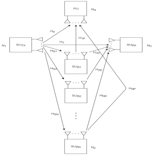
The system model considered in this thesis is a two hop CCRN with multiple relays and multiple antennas at the transmitter, relay and receiver side. The topology is given in Figure 3.1.
Figure 3.1 System model of two hop CCRN.
The secondary transmitter is represented by SUTX having N1 antennas and the secondary receiver is denoted by SURX having N3 antennas. The primary receiver is represented by PU
21 and has N4 antennas. The first relay is represented by SUR1 and the Nth relay by SURN. Each
of the relays has N2 antennas.
In Figure 3.1, the following channel coefficient matrices are used:
HS1: N2×N1 channel coefficient matrix from SUTX to the first relay SUR1. HS2: N2×N1 channel coefficient matrix from SUTX to the second relay SUR2. HSN: N2×N1 channel coefficient matrix from SUTX to the Nth relay SURN. H1D: N3×N2 channel coefficient matrix from SUR1 to SURX.
H2D: N3×N2 channel coefficient matrix from SUR2 from SURX. HND: N3×N2 channel coefficient matrix from SURN from SURX. H3: N3×N1 channel coefficient matrix from SUTX to SURX. H4: N4×N1 channel coefficient matrix from SUTX to PU. H1P: N4×N2 channel coefficient matrix from SUR1 to PU. H1P: N4×N2 channel coefficient matrix from SUR2 to PU. HNP: N4×N2 channel coefficient matrix from SURN to PU.
Let X= {x1, x2, …, xM} be the input sequence of the encoder at SUTX which includes M symbols
selected from any modulation scheme such as phase shift keying (PSK), quadrature amplitude modulation (QAM) or pulse amplitude modulation (PAM). For transmission through N1 antennas, the symbols are encoded into an N1×L1 OSTBC G. Here L1 is the block length of the codeword which is the number of time slots needed for transmission of the codeword. In our work, we assume that all channels are subjected to Nakagami-m fading. Also, the relays and the secondary receiver SURX have perfect channel state information to decouple and
decode their received signals.
3.2 Definition of Outage Probability
Outage probability is defined as the probability that the instantaneous SNR falls below a predefined threshold , i.e.
22
= { ≤ } = ( ) (8)
where, ( ) is the PDF of instantaneous total SNR .
Thus, to quantify the outage for our considered system, we first formulate the , then we derive the CDF of which will finally lead us to an expression for OP.
3.3 Calculation of SNR
To find out the OP in our system model, we should calculate the CDF ( ) of the total SNR which consists of SNR of the relaying transmission and the SNR of direct transmission. The relaying transmission consists of the first hop transmission of the signal from SUTX to the
relays SUR1, SUR2, . . ., SURN and the second hop transmission of the signal from AF relays
SUR1, SUR2, . . ., SURN to SURX. Lastly, direct transmission is from SUTX to SURX.
3.3.1 First hop
In the first hop, the SUTX transmits an OSTBC G over L1 time slots. The code rate of the
OSTBC encoder is given by = / 1. Then, a N2×L1 received signal matrix at SUR1 in
the first time slot is given as
= S1 + (9)
Similarly, the received signal matrices … at SUR2 … SURN are represented as
= S2 + (10)
= SN + (11)
where , = 1,2, … , is the N2×L1 AWGN matrix at SURi whose elements are random
variables (RVs) with zero mean and variance . Furthermore, is a N3×L1 received signal matrixat the destination in the first time slot given by
= SD + (12)
where is the N3×L1 AWGN matrix at SURX whose elements are RVs with zero mean and
variance .
Let and be the average transmit power per symbol and total transmit power through N1 antennas, respectively. The transmit power of OSTBC should satisfy the following condition:
23
| | = 1 = 1 (13)
Therefore, we have
= /( 1 ) (14)
Let Q be the interference power threshold at PU in one time slot, the total interference power that PU can tolerate in L1 time slots is 1. Thus, we have
| | = || || = (15)
Then, the transmit power of each symbol at SUTX should satisfy the following constraint:
= || || (16)
3.3.2 Second hop
In the second time slot, assume that opportunistic relaying is utilized. This means that among L relays, only one relay that provides the highest SNR is selected to be active. Assume that the relay SURj that maximizes the end-to-end SNR at the receiver is selected to forward the
signal. In particular, first, this relay decomposes the received OSTBC signal by using the squaring approach. As a result, the ith decoupled signal
i corresponding to the ith original
symbol xiof the source is given by [11]
i= i + (17)
where is the decomposed noise which is AWGN, having zero mean and variance
N0 . This can be denotes as CƝ (0, N0 ) [11]. The relay SURj then multiplies
these M decoupled signals { } with a scalar gain Aj to create a new symbol sequence { } . Let be the power of each symbol at the relay SURj. Then, we have
= {‖ ‖ }= = ‖ ‖ (18)
This means that the gain is selected as
24 The multiplied symbol sequence { } is utilized as an input to the OSTBC encoder at SURj.
Then, the encoder generates an OSTBC matrix of size × over time slots with the code rate of . Then, the code rate of the OSTBC encoder at the relay SURj is given by
= M/ (20)
Let be the total transmitted power from SURj over all antennas in one time slot. Further,
assume L2 being the number of timeslots over which OSTBC is transmitted from relay. Thus,
we have
= (21)
From (21), we have
= (22)
Then, the × received signal matrix YjD at SURX from SURj is given by
YjD= HHjD + ZZjD (23)
where ZjD is a × AWGN matrix at SURX. Further, HjP is the channel coefficient matrix
from SURj to PU where = 1, 2, … , .
Similarly, the interference from SURj at PU in time slot is given by
YjP = HHjP (24)
As a result, the interference power from SURj at PU in time slot is given by
= N2M (25)
The interference power from SURj at PU in time slot is computed as . Thus, we have
= (26)
Therefore, we can calculate from (26) as
= (27)
25
= (28)
At the destination, using the squaring approach, the ith decoupled signal from the relaying link to destination is obtained as
, = + + (29)
where is the corresponding decomposed AWGN with zero mean and variance . Similarly, the ith decoupled signal from the direct link to destination is expressed as
, = | | + (30)
where is the corresponding decomposed AWGN with zero mean and variance ‖ ‖
= (0, | | ) (31)
As a result, the instantaneous SNR per symbol at SURX from the jth relay is obtained as
=
+
(32)
Similarly, the instantaneous SNR per symbol at SURX from the direct link is formulated as
=
| |
{| | }
(33)
Substituting (16) and (28) into (19), the gain factor at the jth relay is selected as
= | |
| |
(34)
Note that and are AWGN with zero mean and variance and
, respectively. Thus, the noise power of and is
26
{‖ ‖ } = (36)
Substituting (34), (35), (36) into (32), the instantaneous SNR per symbol at SURX from the
relaying link is further calculated as
=
.
| | + | | (37)
Similarly, the instantaneous SNR per symbol at SURX from the direct link is obtained as
= | |
| |
(38)
Let = ; = ; | | = ; | | = ; | | = ; =
; = and μ = . Then, the instantaneous SNRs at the SURX from relaying link and
direct link are obtained, respectively, as
= μ + (39) = μ (40)
At the receiver, it is assumed that selection combining takes place where the receiver picks the antenna with highest SNR and discards the information from all the other antennas. As a result, the total SNR of the system when selection combining is utilized at the receiver is obtained as
= ( , , , , … … … ) (41)
3.4 Derivation of CDF of SNR
To facilitate the further calculation, we provide here the PDF and CDF, respectively, of the channel power gains of all the links:
27 ( ) = ᴦ (42) ( ) = ᴦ (43) ( ) = ᴦ( ) (44) ( ) = ᴦ( ) (45) ( ) = ᴦ( ) (46) and ( ) = 1 − ! (47) ( ) = 1 − ! (48) ( ) = 1 − ! (49) ( ) = 1 − ! (50) ( ) = 1 − ℎ! (51)
To calculate the outage of the system, we need to obtain an expression of the CDF of . Since
, , … , are dependent random variables on and , we need to first
calculate the conditional CDF of on , . From (40), the conditional CDF of the SNR of the direct link on and is calculated as
| , = (52)
From (41), the conditional CDF of the total SNR on , is derived as
28 By substituting (52) into (53) we rewrite | , as
| , =
μ | ,
(54)
As a result, the CDF of can be calculated as
| , =
μ | , ( ) ( )
(55)
From (39), | , can be calculated as
| , = ∫ Pr {
≤ } ( )
(56)
To further calculate | , , we get the following two cases in (56):
If ≤ , Pr ≤ = 1 (57) If > , we have Pr ≤ μ − = μ − (58)
Now substituting (57) and (58) into (56), we can obtain | , as
| , =
μ +
μ − ( ) (59)
After some algebraic modifications, we can rewrite | , as
| , = μ +1 μ + μ + μ (60) Using (47), we have
29 + μ = 1 − μ + μ ! (61)
Substituting (61) into (60), | , can be rewritten as
| , = μ + 1 − μ −1 μ μ + μ ! × + μ (62)
Using the binomial formula ( + ) = ∑ , | , can be rewritten as
| , = 1 − 1 μ ∑ μ μ ! × + μ (63)
where is a binomial coefficient given by the expression = !
!( )! From (43), we have + μ = ᴦ + μ (64)
30 | , = 1 −1 μ − 1 × μ ! × ᴦ (65)
To solve the integral in (65), we utilize Equation (3.471. 9) of [16] which leads to | , = 1 −1 μ − 1 × μ ! (66) × ᴦ 2 2
where 2 is Basel function of an imaginary argument as defined in [16].
Substituting (49) into (52), the conditional CDF of SNR on , from the direct link can be calculated as | , = μ = 1 − μ ! (67) From (55) F ( ) = μ | , ( ) ( ) (68)
31 ( ) = 1 − μ ! 1 −1 μ − 1 × μ ! × ( ) ᴦ( ) 2 2 μ × ᴦ( ) ᴦ( ) (69)
3.5 Expression of Outage Probability
The analytical expression for the OP of the considered CCRN is given by
= ( ) (70) Substituting (69) into (70), we get
= 1 − μ ! 1 −1 μ − 1 × μ ! × ( ) ᴦ( ) 2 2 μ × ᴦ( ) ᴦ( ) (71)
32
4
N
UMERICAL AND SIMULATION RESULTS
In this section, we present the numerical and simulation results for the performance metric derived in Chapter 3. For the entire analysis, we set the outage threshold value at = 5dB. The OP is the metric which is used to study the effect of the number of relays, number of antennas and fading parameters on the system performance. The different scenarios are discussed below where each scenario deals with a particular parameter.
4.1 Scenario 1: Varying the Number of Relays
In this scenario, we have varied the number N of relays. The examined cases are selected as follows:
x Case 1: N=1 x Case 2: N=2 x Case 3: N=4
The other parameters like the number of antennas and fading parameters are kept constant for all the cases and are set as follows:
Number of antennas At SUTX: N1=2 At SUR: N2=2 At SURX: N3=2 At PU: N4=2 Fading parameters x m1= 1, m2=1, m3=1, m4=1, m5=1 x d1= 0.5, d2=0.5, d3=0.8, d4=1.2, d5=1.2
On the basis of the values obtained from simulation and numerical results, the graphs of outage probability versus interference-to-noise ratio Q/N0 plotted for the cases mentioned above, are shown in Figure 4.1.
33 Figure 4.1 Outage probability versus interference power-to-noise
ratio Q/N0 for different relay configurations.
Comparing Case 1 (N=1) and Case 2 (N=2), we can infer that the outage probability significantly decreases as the number of relays increased from one to two. There is also a significant improvement in the outage probability when the number of relays is increased from two to four as in Case 3 (N=4). From this, we can conclude that as the number of relays is increased the outage probability decreases. If we keep on increasing the number of relays the outage performance gets better. However, the difference in outage performance gets smaller as we increase the number of relays. As we can observe that there is significant improvement when we increase the number of relays from 1 to 2 but when we increase the number of relays from 2 to 4 the improvement is not as much.
4.2 Scenario 2: Varying the Number of Antennas
In this scenario, we varied the number of antennas N1, N2, N3, N4 at SUTX, SUR, SURX and
PU, respectively.
The examined cases are selected as follows: x Case 4: (N1, N2, N3, N4): (2,2,2,8)
34 x Case 6: (N1, N2, N3, N4): (2,2,2,2)
x Case 7: (N1, N2, N3, N4): (2,8,2,2)
x Case 8: (N1, N2, N3, N4): (2,2,8,2)
The other parameters like the number of antennas and fading parameters are kept constant for all the cases. They are given below.
Number of relays N=4 Fading parameters
x m1=0.5, m2=0.5, m3=0.5, m4=0.5, m5=0.5.
x d1=0.5, d2=0.5, d3=0.8, d4=1.2, d5=1.2.
On the basis of the values obtained from simulation and numerical results, the graphs of outage probability versus interference-to-noise ratio Q/N0, plotted for Cases 4-8 are shown in Figure 4.2.
Figure 4.2 Outage probability versus interference power-to-noise ratio Q/N0 for different antenna configurations.
Case 4 gives the worst outage performance when compared to rest of the cases. In this case, a higher number of antennas is used at the PU terminal which leads to higher outage probability.
By observing the above graphs, we divide our analysis into two main parts. The first analysis at low SNR and second is at higher SNR. When the SNR values are low, Case 6 performs
35 better than Case 5 but at higher SNR, Case 5 performs better than Case 6. This is because of higher coding gain and diversity gain at the transmitter.
When we analyze Case 7 and Case 8, outage performance of Case 8 is better at low SNR because of better diversity gain at the receiver but Case 7 performance gets better than Case 8 with the increase in SNR as the coding gain achieved at the relays outperforms the advantages of diversity gain at the receiver.
4.3 Scenario 3: Varying the Fading Severity Parameter
In this scenario, the fading severity parameters (m1, m2, m3, m4, m5) are varied. The examined
cases are selected as follows:
x Case 9: m1=m2=m3=m4=m5=0.5
x Case 10: m1=m2=m3=m4=m5=1
The other parameters are kept constant for all the cases. They are as follows: Number of relays N=4 Number of antennas At SUTX:N1=2 At SUR: N2=2 At SURX: N3=2 At PU: N4=2 Distance parameters (d1, d2, d3, d4, d5) = (0.5,0.5,0.8,1.2,1.2)
Outage probability versus interference-to-noise ratio Q/N0, plotted for the cases mentioned above are shown in Figure 4.3.
36 Figure 4.3 Outage probability versus interference power-to-noise
ratio Q/N0 for different channel mean powers.
Case 9 and Case10 provide an insight into the effect caused when we vary the fading severity parameter m. In Case 10, when the fading severity parameter is 1, the outage performance is better when compared to Case 9 where fading severity parameter is 0.5. This is because, the smaller m larger the amount of fading. As m→∞the Nakagami-m channel converges to AWGN channel which is nonfading.
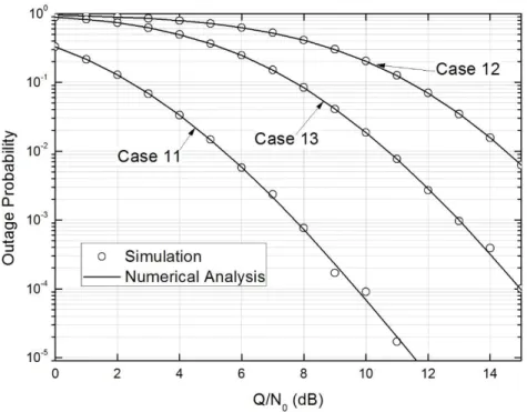
4.4 Scenario 4: Varying the Distance
In this scenario, we vary the distances d1, d2, d3, d4, d5 between the links SUTx→SUR,
SUR→SURx, SUTx→SURx, SUTx→PU, SUR→PU, respectively, which effects the channel
mean power. The examined cases are selected as follows: x Case 11: d1=0.5, d2=0.5, d3=0.8, d4=1.2, d5=1.2.
x Case 12: d1=1.12, d2=1.12, d3=1.2, d4=1.2, d5=1.2.
x Case 13: d1=0.5, d2=0.5, d3=0.8, d4=0.8, d5=0.8.
The other parameters are set as follows: Number of relays N=4.
37 At SUTX:N1=2
At SUR: N2=2
At SURX: N3=2
At PU: N4=2
Fading severity parameters m1=m2=m3=m4=m5=0.5
The outage probability versus interference-to-noise ratio Q/N0, are shown in Figure 4.4.
Figure 4.4 Outage probability versus interference power-to-noise ratio Q/N0 for different values of distance.
In Case 11, the distance is chosen such that the channel mean power between the links SUTx→SUR, SUR→SURx and SUTx→SURx is higher than the channel mean power between
the links SUTx→PU and SUR→PU. When we compare Case 11 with Case 12, as we have
increased the distances d1, d2, and d3, it reduces the channel mean power between SUTx→SUR,
SUR→SURx and SUTx→SURx. This results in Case 11 having better outage performence.
Case 13 illustrates that decreasing the distance between SUTx→PU and SUR→PU while
keeping all other distances the same as in Case 11, leads to a degradation in outage performance. This is because the channel mean power has increased between SUTx, PU and
38 Thus, as the distance between the SU components and PU is increased, we get better outage characteristics when compared to the case where we increase the distance among the SU components, i.e. SUTx, SURx, SUR.
39
5
C
ONCLUSION AND
F
UTURE
W
ORKS
In this thesis, we have investigated the performance of a MIMO CCRN under the impact of Nakagami-m fading. In Chapter 3, analytical expressions for the PDF and CDF of the SNR for the considered system model have been derived. The expression for outage probability is obtained on which the performance of the system is analyzed. In Chapter 4, simulation results obtained in MATLAB are compared with the numerical results obtained with Mathematica. Specifically, the outage probability is investigated for a range of SNR values. Various parameters like the number of relays, number of antennas at the transmitter, receiver, and relay, and the fading parameters have been varied to study their effect on the outage performance of the system.
Based on the observations made in Chapter 4, several insights have been gained as follows. Increase in number of relays from N=1 to N=2 significantly improves the outage performance whereas a further increase from N=2 to N=4 gives not as much improvement. The next analysis was done by varying the number of antennas at SU components and the PU. The consequence was substantial and it was studied that an increase in the number of antennas at the PU degrades the system performance in the secondary network. Also, when the number of antennas at the SU terminals are increased the outage performance improved. When the fading severity parameter m was varied, it was learnt that as m is increased, the outage probability decreases. Lastly, the distances between SU components and PU were changed which effected the channel mean powers. It was concluded that higher channel mean powers between SUTx, SURx and SUR generate lower outage probability and high channel mean
powers between PU and SUcomponents resulted in poorer outage performance.
In this thesis, we have restricted ourselves to the analysis of system performance for selection combining in terms of outage probability. The future works may include extensions using combining techniques like equal gain combining, maximal ratio combining etc. The performance in terms of symbol error rate and ergodic capacity can also be used to analyze system performance. The fading channel assumed in this thesis is a Nakagami-m channel. The future work may also include studying the performance of the system under the impact of a different channel like κ − μ shadow fading for various parameters.
40
R
EFERENCES
[1] K. B. Letaief and W. Zhang, “Cooperative communications for cognitive radio networks,”
Proceedings of the IEEE, vol. 97, no. 5, pp. 5878–893, Apr. 2009.
[2] L. Li, X. Zhou, H. Xu, G. Y. Li, D. Wang, and A. Soong, “Simplified relay selection and power allocation in cooperative cognitive radio systems,” IEEE Transactions on Wireless
Communicatons, vol. 10, no. 1, pp. 33-36, Jan. 2011.
[3] J. Lee, H. Wang, J. G. Andrews, and D. Hong, “Outage probability of cognitive relay networks with interference constraints,” IEEE Transactions on Wireless Communications, vol. 10, no.1, pp. 390-395, Feb. 2012.
[4] T. Duong, V. N. Q. Bao, G.C. Alexandropoulos, and H.-J. Zepernick, “Cooperative spectrum sharing networks with AF relay and selection diversity,” Electronic Letters, vol. 47, no. 20, pp. 1149-1151, Sept. 2011.
[5] A. Louni and B. H. Khalaj, “Distributed beam-forming and power control in multi-relay underlay cognitive radio networks: a game theoretical approach,” in Proc. IEEE Cognitive Radio Oriented
Wireless Networks and Communications, Cannes, France, Jun. 2011, pp. 71-75.
[6] V. Tarokh, H. Jafarkhani, and A. R. Calderbank, “Space-time block codes from orthogonal designs,” IEEE Transactions on Information Theory, vol. 45, no. 5, pp. 1456-1467, Jul. 1999. [7] I. H. Lee and D. Kim, “Achieving maximum spatial diversity with decouple-and-forward relaying
in dual-hop OSTBC transmissions,” IEEE Transactions on Wireless Communications, vol. 9, no.3, pp. 921-925, Mar. 2010.
[8] S. Chen, W. Wang, X. Zhang, and Z. Sun, “Performance analysis of OSTBC transmission in amplify-and-forward cooperative relay networks,” IEEE Transactions on Vehicular Technology, vol. 59, no. 1, pp. 105-113, Jan. 2010.
[9] T. Q. Duong, G. C. Alexandropoulos, H-J. Zepernick, and T. A. Tsiftsis, “Orthogonal space time block codes with CSI-assisted amplify-and-forward relaying in correlated Nakagami-m fading channels,” IEEE Transactions on Vehicular Technology, vol. 60, no. 3, pp. 882-889, Mar. 2011. [10] F. Wei, Z. Yang and Q. Zhu, “Throughput analysis of cognitive radio with OSTBC between
primary and secondary users,” in Proc. IEEE Wireless Communications Networking and Mobile
Computing, Chengdu, China, Sept. 2010, pp. 1-5.
[11] T. M. C. Chu, H. Phan, and H.-J. Zepernick, “Performance analysis of MIMO cognitive amplify-and-forward relay networks with orthogonal space-time block codes,” Wireless
Communications and Mobile Computing, DOI:10.1002/wcm.2449, Jan. 2014.
[12] L. Sibomona, “Performance analysis of cognitive radio networks under spectrum sharing and security constraints,” Ph.D. dissertation, Department of Communication Systems, Blekinge Institute of Technology, Karlskrona, Sweden, 2016.
[13] T. M. C. Chu, “On the performance assessment of advanced cognitive radio networks,” Ph.D. dissertation, Department of Communication Systems, Blekinge Institute of Technology, Karlskrona, Sweden, 2015.
41 [14] F. Gharari, “Performance analysis of piecewise-and-forward relay network on Rayleigh fading
channel,” M.S. thesis, Department of Applied Signal Processing, Blekinge Institute of Technology, Karlskrona, Sweden, 2015.
[15] R. Sannegowda and V. Aalo, “Performance of selection diversity systems in a Nakagami fading environment,”in Proc. IEEE, Southeastcon '94. Creative Technology Transfer - A Global Affair., Miami, Florida, pp. 190-195, Apr. 1994.
[16] I. S. Gradshteyn and I. M. Ryzhik, Table of Integrals, Series and Products, 7th ed. Academic Press, 2000.
[17] J. Mitola III, “Cognitive radio: An integrated agent architecture for software defined radio,” Ph.D. dissertation, Royal Inst. of Technology, Stockholm, Sweden, 2000.