A Radial-Ulnar Deviation and
Wrist-Finger Flexion Analysis
Based on Electromyography
Tanzim Kawnine
A Bachelore of Science Thesis in Electronics
Mälardalen University, Sweden
Department of Computer Science and Electronics
2008
Supervisor & Examinator: Baran Cürüklü
Abstract
This study is aimed to determine the electromyographic signals of the forearm, using Ag/AgCl electrodes. The four major muscles of forearm, which are providing the bioelectrical currents, have been displayed and analysed to determine the different activities. In order to record the signals, an EMG device has been developed and installed and a schematic has also been presented in this paper.
Content
Chapter 1: Introduction
... 5
Chapter 2: The Forearm Muscles
... 7
Chapter 3: Physiology of EMG
... 9 3.1 The Nervous System and Muscle Tissues
... 10 3.2 Action Potential
... 11 3.3 Amplifier and EMG Signals
... 12
Chapter 4: Method and Materials
... 14 4.1 Preamplifier and Body Reference Circuit
... 14 4.2 Gain and Bias Adjustment
... 15 4.2.1 Amplifier (the additional gain)
... 16 4.2.2 Bias Adjustment
... 17
Chapter 5: Result
... 20
Chapter 6: Future Work
... 23 6.1 Body Reference Circuit
... 23 6.2 Analogue/Digital Converter ... 24 6.3 Textile Electrodes ... 24 Chapter 7: Conclusion ... 25 Acknowledgement ... 27 Chapter 8: Bibliography ... 28 Internet websites ... 29
Chapter 1: Introduction
EMG, it is a nerve conducting test, performed by measuring the bioelectric signals from the muscle of a human body. Muscular movements cause the action of muscles and nerves, which provide electrical currents. These currents are generated by the interchange of ions across the muscles which make a part of the signalling process for the muscle fibres to contract. It can be measured by applying conductive elements or electrodes to the skin surface, or invasively within the muscle. It is non-invasive and can be conducted very easily with minimal risk to the subject.
The main object of this thesis is to design and develop hardware for measuring EMG signals from real human muscles of forearm. The provided signal will help us to understand the different movements of the muscles of forearm.
Measurement of surface EMG is dependent on the amplitude of the surface EMG signal. The signal varies from μV to mV range. Since the signal level is to low to capture on the display, it is required to amplify the signal level to a TTL level (between -5 volts to +5 volts). Many critical factors should be considered before the signal is displayed properly, such as the electrical signals are distorted by noises and artefacts. Additional DC current could also provide offset to the EMG signal. Without a proper ground reference, the signal could be misleading. Finally yet importantly, the size of the device should be considered.
The basic hand muscle activity is located in forearm. The four muscle groups are 1) the extensor carpi radialis 2) the extensor communis digitorun 3) the extensor carpi uilnaris and 4) Flexor carpi radialis. The EMG device which has been developed for this project has only one channel. By attaching two electrodes from each muscle group to the device, the EMG signal has been analysed, when the muscle contraction and various hand movements were made.
Chapter 2 provides descriptions of upper mentioned muscle groups and their location within the forearm.
In chapter 3, the physiology of EMG has been discussed. It contains brief information about the nervous system and muscle tissue applications and also about the action potential of the muscles.
Chapter 4 provides a detail of implementation of the EMG device with a basic description of preamplifier, filtration and additional amplifier with bias adjustment. Each of the components is described through circuit diagrams and key equations.
Chapter 5 discusses the result of the movements of different muscles groups of forearm. The experiment consisted of radial and ulnar deviation and also wrist and finger flexion and extension of the hand. The various signal patterns of the muscles has been illustrated in this chapter.
Chapter 2: The Forearm Muscles
The forearm is a structure on the upper limb. The forearm consists of two bones, the radius and ulna. It contains many muscles such as the extensor carpi radialis, extensor digitorum comunis, extensor carpi ulnaris, Flexor carpi radialis and a few more. These muscle are chosen to be described in this chapter because of their contraction and relaxation states have been measured and analysed by this EMG measuring device.
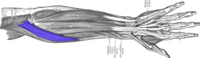
2.1 Extensor carpi radialis
The extensor carpi radialis is located beneath the Brachioradialis (see figure 2.1). It is one of the main muscles that control the movement of the wrist. It starts at the lateral side of the humerus and it is inserted into the dorsal surface of the base of the second metacarpal bone [11]. The muscle is an extensor at the wrist joint. It manipulates the wrist to move the hand toward the thumb and away from the palm.
2.2 Extensor digitorum communis
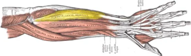
The Extensor digitorum communis arises from the lateral epicondyle of the humerus, by the common tendon; from the intermuscular septa between it and the adjacent muscles, and from the antibrachial fascia [11]. The Extensor digitorum communis extends the phalanges, then the wrist, and finally the elbow. It tends to separate the fingers as it extends them [C].
Figure 2.2: Extensor digitorum communis visible in blue at center.
http://upload.wikimedia.org/wikipedia/common s/5/5f/Gray418.png
Figure 2.1: Superficial muscles of the forearm. Extensor carpi radialis longus visible in blue.
http://upload.wikimedia.org/wikipedia/commons/ 0/07/ECR-longus.png
2.3 Extensor carpi ulnaris
The Extensor carpi ulnaris is located on the ulnar side of the forearm (see figure 2.3 below). It originates from the lateral epicondyle of the humerus, and is inserted into the prominent tubercle on the ulnar side of the base of the fifth metacarpal bone [11]. The Extensor carpi ulnaris extends the wrist, but when acting alone inclines the hand toward the ulnar side; by its continued action it extends the elbow-joint [D].
Figure 2.3: Extensor carpi ulnarisvisible in yellow at centre right.
http://upload.wikimedia.org/wikipedia /commons/5/5f/Gray418.png.
Figure 2.4: Flexor carpi radialis visible in blue in the centre of forearm.
http://upload.wikimedia.org/wikipedia/common s/5/59/Flexor-carpi-radialis.png
2.4 Flexor carpi radialis
Flexor carpi radialis (see figure 2.4) is another muscle of the forearm that acts to flex of the hand. The muscle arises from the medial epicondyle of the humerus and inserts into the palmer surface of the base of the second metacarpal [11].
Chapter 3: Physiology of EMG
EMG stands for electromyography, also referred to as myoelectric activity and measuring the electrical impulses of muscles at rest and during contraction. Muscle tissues conduct electrical potential similar to the way nerves do and these electrical impulses are called action potentials. The information present in the muscle action potential can be recorded by applying the surface EMG method. It is important to consider two main issues when the detection and recording of EMG signals occur. The first is the signal-to-noise ratio. It is the ratio of energy in the EMG signals to the energy in the noise signal. Noise is something that is not desired in a pure EMG signal. The second one is the distortion of the signal.
The EMG signal is picked up by electrode and amplified. It usually needs thousand times of amplification before it could be shown on a display and can be recorded. By amplifying the input signal, the noise signals are also amplified from the skin and other factors that may affect the outcome signals. The point of interest of the signal is the amplitude, which has a range between 0 to 20 millivolts (peak to peak). The frequency of an EMG signal is between 0 to 500 Hz. However, the usable energy of EMG signal is between 50 to 150 Hz.
Many dependent factors could affect surface EMG. Electrical noise can be categorised into the following types:
1. Inherent noise in electronic equipments: All electronics equipments cause noise. It is next to impossible to eliminate the perturbed signals but by applying proper filter, the noise can be reduced to minimum.
2. Ambient noise: Electromagnetic radiation is the source of ambient noise. Ambient noise level is the background noise level, reference sound level or room noise level. “It has amplitude that is one to three orders of magnitude greater than the EMG signal [6]”.
3. Motion artefacts: Two main sources give rise to motion artefacts, namely electrode interface and electrode cable. A proper design of the circuitry and shield wires will reduce the noise.
The following steps can do the maximisation of the quality of EMG signal:
1. The signal to ratio should consist of the highest amount of data from EMG signal and as minimum amount of noise as possible.
2. The distortion of EMG signal should be as minimum as possible with no unnecessary filtering.
3.1 The Nervous System and Muscle Tissues The brain, the spinal cord and peripheral nerves are the three main parts of the nervous system. It controls the communication system of the body. There are two main types of tissues in our nervous system: excitable tissue and non-excitable tissue. The non-excitable cells are called neurones, which communicate with different parts of the body, responding to and transmitting messages in the form of nerve
impulses from one part of the body to another. Figure 3.1: Skeletal muscle structure
http://www.octc.kctcs.edu/gcaplan/anat/images/ Image285.gif
Non-excitable tissues do not response to voltage or any other conventional stimulus.
Excitable tissues can be classified into four components, namely sensory receptors, neurone cells bodies, axons and muscle fibres. A contact with a hot surface will cause pain and pressure which will be transmitted by sensory receptors. The neurone sends the message along a nerve axon (also called nerve fibres) to the spinal cord. There are two types of axons: the afferent axon and efferent axon. The afferent axon also called as sensory axon, transmits the signals to the nervous system and carries information from sensory receptor to the spinal cord or brain. The efferent axon (motor axon) originates at the spinal cord transmits the information through the body parts.
A muscle consists of specialised cells capable of contraction and relaxation. These cells generate forces, help us to move and give us the ability to communicate and make expressions. The four main functions of the muscle tissues are: producing motion, moving substances within the body, providing stabilisation and generating heat. The tissues also can
be identified based on structure, contractile properties and control mechanism: (i) skeletal muscles (ii) smooth muscle (iii) cardiac muscles. The EMG is applied to the study of skeletal muscle.
As it is shown on figure 3.1, that skeletal muscles are attached to the bone and the muscle contraction of skeletal muscles are responsible for movement of the skeleton. The muscle contraction initiates by impulses in the neurones to the muscle. These neurones are called as “motor neurone”. One motor neurone usually supplies stimulation to many muscle fibres.
3.2 Action Potential
Each nerve impulse triggers an electrical discharge, or action potential, in each of the muscle fibres that it stimulates. Under normal
condition, Na+ and Ca+ are more concentrated
in the extra cellular fluid and K+ is more
concentrated with in the cell. Na+ generates
the electrical signals. When a cell goes from
resting to an excited state, it increases its Na+
permeability. Then the Na+ molecules enter
the cell through voltage-gated channels. The
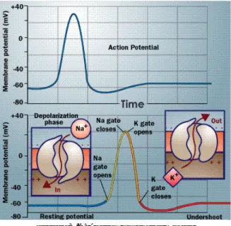
Figure 3.2: Action potential model
http://static.howstuffworks.com/gif/nerve-12.gif
extra positive charge of Na+ to the intracellular fluid causes the cell to become depolarised
and initiate an action potential. The action potential starts at the point of innervations and spread along the muscle fibres toward the two ends of the fibre. These AP’s activate the contractile apparatus inside the muscle fibres. It also produces an electrical potential in the surrounding muscle tissue, which can be detected by a needle or fine-wire electrode.
As it was mentioned earlier, the nervous system controls a muscular contraction by turning motor units on and off and by controlling their discharge rates. When a motor unit discharges, the electrical potentials from all the muscle fibres of the motor unit sum together to produce a compound potential called the Motor Unit Action Potential (MUAP). This is a matter of one to several milliseconds. The electrodes play an important role here because the exact size and shape of MUAP depends on where the electrodes are placed on the skin.
MUAPs differ from one motor unit from another with different shapes, but by the same electrode from the same motor unit have more or less the same shape.
An EMG signal is the train of Motor Unit Action Potential (MUAP). The signal contains the muscle response to neural stimulation. It appears randomly in nature and is modelled as a filtered impulse process. “The MUAP is the filter and the impulse process stands for the neurone pulses” [6].
3.3 Amplifier and EMG Signals
An EMG amplifier amplifies the signals generated by the muscles. It boosts the low power signal to high power signal, so the signal is usable to perform work. The amplification increases the signal level and protects an electrical interference during transmission. The amplified signal can also be stored in a device or displayed on a oscilloscope.
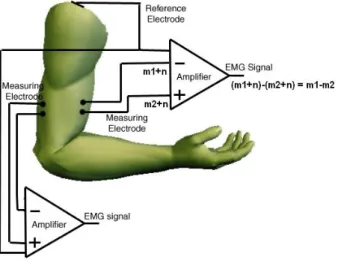
A differential amplifier has the ability to eliminate the noise from the EMG signal.
Figure 3.3 shows the diff-amp with two inputs, which are subtracted, and the signal
difference is amplified and become the output signal.
Figure 3.3: A schematic of the differential amplifier configuration
http://p3.smpp.northwestern.edu/BMEC66/weightlifting/images/armelectrode.jpg
A perfect subtraction is next to impossible. Therefore, a Common Mode Rejection Ratio (CMRR) is applied to measure the accuracy of subtraction in each amplifier. If the CMRR value is at 90 dB, it could discard the noise. However, most of the amplifiers nowadays could make a CMRR value of 120 dB. All though, there are some noises that still could exist. The
noise could be injected into the signal by a stray capacitance and then the signal is amplified. As a result, a degrading signal can be seen on the display.
An amplifier itself is an effective filter. The electrode itself usually has lower impedance in a case of higher frequencies and has higher impedance for lower frequencies. The electrodes, cables and amplifier create an implicit filter effect. This filter could cause errors in the signal if it is not designed carefully. To reduce an implicit capacitance effect, the electrodes should be placed near the amplifier, which means the amplifier should be located as close to the signal source as possible.
Chapter 4: Method and Materials
The EMG machine is designed to measure and record signal from human nerves and muscles. A part of the machine known as differential amplifier compares the electrical activity at one point to a reference point, which is considered zero. This will determine the difference between the active point and the reference point and shows the difference on the display of the oscilloscope for interpretation.
The amplifier is set to display various levels of gain. The sensitivity of the amplifier increases or decreases the size of the waveforms of the forearm on the display. The increasing sensitivity can cause an increase in level of noise and artefacts which make the small electrical potentials very difficult to identify. Filters could be applied to minimise the background noise and artefacts, enhancing the electrical potential to be seen on the screen.
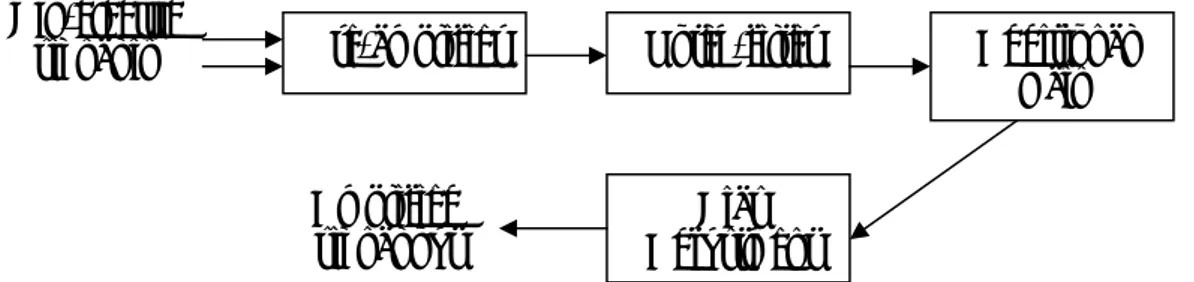
Bio-electric
signal in Pre-amplifier Notch-filter
Amplified
signal out Adjustment Bias
Additional Gain
Figure 4.1: A simple block-diagram of EMG device
4.1 Preamplifier and Body Reference Circuit
To build an EMG device, an instrumentation amplifier is needed. A BURR-BROWN INA2128 chip is used for the preamplifier and OPA2604 for the body reference circuit and an OPA2277 for the notch filter. The preamplifier is a type of a differential amplifier. The data sheet of INA2128, OPA2604 and OPA2277 is shown in Bibliography.
This figure 4.2 shows a preamplifier circuit and the body reference circuit from only one channel.
Figure 4.2: Preamplifier with body reference circuit
The equation for gain is [5]:
G 50 1 R k Gain= +
R1 = R2 = 22 ohm and RG = 22 x 2 = 44 ohm, and the gain is approximately 1137 times. It is
sufficient for the amplification of our EMG signals. The body reference circuit that is connected to the preamplifier acts as a ground. The details of the circuit will be discussed later.
4.2 Gain and Bias Adjustment
This section is considered as the second stage of the EMG amplifier. The amplifier and the bias adjustment help us with an ability to adjust or correct the output signals in different circumstances. For instance, if the bioelectric signals of the forearm do not have enough amplitude after the pre-amplification stage or if the signal is not high enough for an A/D converter or perhaps the signal still has a bias or offset. These problems could be resolved by applying the gain and bias adjustment.
The EMG machine has only one channel and it has an individual gain adjustment unit and an individual bias adjustment unit. These units are applied after the signals passed through the pre-amp stage and the filtering stage, where the noises and artefacts are reduced to minimum level.
This EMG device has a limitation of the gain and the bias adjustment. It can be amplified about 21 times. The bias adjustment adjusts the signal up or down by the level of ±9 volts. In the nature of op-amp, the output cannot be more or less than the power supply voltage. For instance, the amplifier is fed with one volt, which has a gain equal to four, and the offset has increased by positive 2 volts, the output of the op-amp would be 6 volts. This is acceptable because the output voltage is still within the voltage range. However, if the input level is the same but the gain of the op-amp has changed from four to eight times with the same offset level, the calculated output would be 10 volts because of the characteristics of the op-amp.
The amplifier in the device uses basic non-inverting amplifier circuit. The gain could be adjusted by using a potentiometer, which is parallel to 10k (R2), shown on the next page (see
figure 4.5).
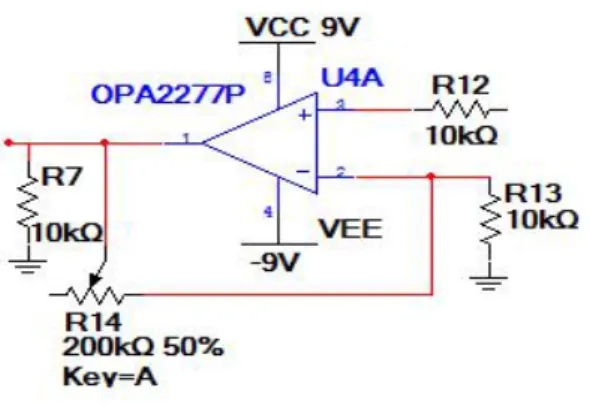
4.2.1 Amplifier (the additional gain)
Figure 4.5: Amplifier circuit with gain adjustment
The gain can be computed by:
) 1 ( ) 1 ( 13 14 13 14 R R Gain V V R R V V in out in out + = = + =
This non-inverting amplifier circuit is built by using OPA2277 chip, a dual op-amp. The purpose of using an OPA2277 is to use the inputs for the gain and the bias adjustment circuit, making the whole circuit looks more compact.
The compensation resistor R12 is placed to reduce the error in the output voltage, which is equal to the parallel combination of R14 and R13. R14, the potentiometer is used to increase or decrease the additional gain. When R14 is adjusted to 0, there is no additional gain (gain = 1). On the other hand, the R14 is adjusted to the maximum of 200k; the gain is equal to 21 times.
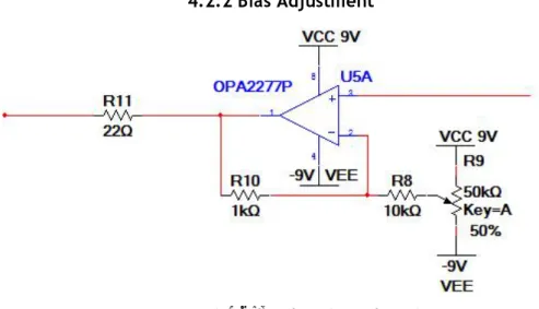
4.2.2 Bias Adjustment
Figure 4.6: Bias adjustment circuit
Bias adjustment circuit increases or decreases the reference level of the signal. Reference level of a signal is at ground line or zero volts. If it is not at the ground line, or if the reference level needs to be changed, the bias adjustment enables us to adjust the reference level or the desired level.
The ground level is created by using a potentiometer. The change of the potentiometer affects the reference level to the output voltage. To adjust the reference level at the output voltage, the calculations of three different cases are needed. When the potentiometer R9 is
adjusted to 0%, 50% and 100%, Vout is equal to:
adj in
out V Gain V
V =( × )± Where, V1 < Vadj < V2.V1 = +Vcc and V2 = -Vcc.
Therefore 0%, 50% and 100% are the values of +Vcc, ground level or zero and -Vcc
respectively.
Using the equation from the previous page, the output of the circuit can be computed as follows:
• At 0% of R9: (R9= 0 ohm, Vadj = +Vcc volts) ) 1 ( 8 10 R R Gain= + cc in out V R R V V = (1+ )+ 8 10
• At 50% of R9 (R9= R9/2 ohms, Vadj = 0 volts)
) 2 1 ( 9 8 10 R R R Gain + + = ) 2 1 ( 9 8 10 R R R V Vout in + + =
• At 100% of R6: (R6 = R6 ohms, Vadj = -Vcc volts)
) 1 ( 9 8 10 R R R Gain + + = cc in out V R R R V V − + + = (1 ) 9 8 10
The output of the circuit from the second equation is referenced by a virtual ground level. While on the first and the third equation, the additional voltages were added to the output level either positive or negative. By using this concept, the offset of the output voltage can be adjusted.
In this EMG device, an OPA2277 chip is used for one channel. OPA2277 has ultra low offset 10µV, high open-loop gain (134 dB), high CMRR with four inputs, which is an outstanding chip for the whole gain and bias circuit system [4].
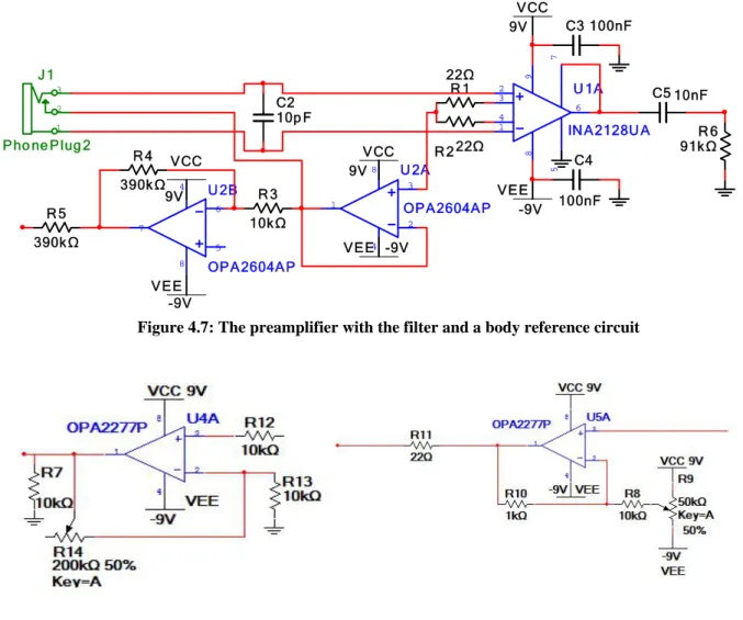
U 1A IN A2128U A 2 1 8 9 6 5 3 4 7 C2 10p F J 1 Pho ne Plug 2 2 1 3 R 1 22Ω R 2 22Ω U 2A OPA2604AP 3 2 4 8 1 U 2B OPA2604AP 5 6 4 8 7 R 3 10kΩ R 4 390k Ω R 5 390k Ω VCC 9V C3 100nF C4 100nF C5 10nF R 6 91kΩ VEE -9V VEE -9V VCC 9V VCC 9V VEE -9V
Figure 4.7: The preamplifier with the filter and a body reference circuit
Chapter 5: Result
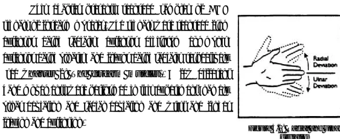
This chapter presents recorded samples of EMG signals of forearm muscles. The signals were recorded from extensor carpi radialis, extensor digitorum communis, extensor carpi ulnaris, and flexor carpi radialis respectively (see Chapter 2: The forearm muscles). A few different hand movements were performed in this experiment, namely ulnar deviation and radial deviation and wrist and finger flexion and extension.
Figure 5.1: Radial and ulnar deviation
The objective of the experiment is to measure and recognise the various signals of the upper mentioned muscle groups and categorise the different shapes of the signals and measure the amplitudes. The result of each measured muscles of forearm is following:
Extensor carpi radialis
Behavioural test: Radial-ulnar deviation and wrist flexion
Firstly, two electrodes were connected to this muscle group of the forearm. While doing the experiment, the wrist was supported in a neutral position and hand was out over the edge of the table.
Extensor carpi ulnaris
Behavioural test: Radial-ulnar deviation and wrist flexion
Again, two electrodes were attached to the muscle. The hand was placed exactly in the same way as it was done while measuring the previous muscle group.
Figure 5.3 : Ulnar & radial deviation of extensor carpi unlaris of the forearm
Note, the burst of activity at extensor carpi ulnaris during the ulnar-radial deviation and wrist flexion and compare the signal behaviours to figure 5.2.
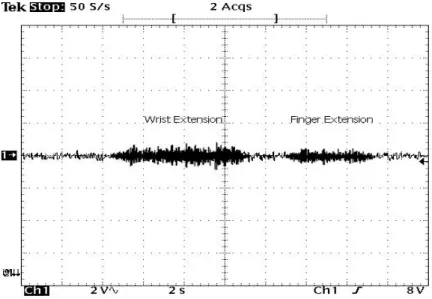
Extensor digitorum communis
Behavioural test: Wrist flexion and finger extension
The figure below shows recordings from extensor digitorum during two movements of the hand, namely finger and wrist extension.
Flexor carpi radialis
Behavioural test: Wrist flexion (up/down)
During this experiment, the wrist was flexed with finger relaxed and was in neutral position. Below the recorded signal is presented:
Chapter 6: Future Work
6.1 Body Reference Circuit
Our EMG machine has one channel to measure the signal of the muscles of forearm. Due to limitation of time, only one channel could be created, but if the device would have four channels instead of one, it could have been built by applying four preamplifiers and four body reference circuits. It is possible to combine these four body reference circuits into one common mode reference circuit and reduce the number of electrodes contacts from four to one. An inverting summing amplifier circuit will provide an average output result. The value of each
resistor should be calculated. In this case, by
giving the correct ratio to R2/ R1, the result is
approximately equal to ¼.
Figure 6.2: Inverting summing amplifier
The figure above shows the inverting summing amplifier circuit for four inputs. Resistor
R3 is a compensating resistor to ensure that positive and negative inputs of the op-amp have
similar resistance to ground. The bias current of the op-amp that can cause problems
sometimes, could be minimised by using the resistor R3. To find out the value of resistor R3,
we could calculate the parallel combination of R1 and all the input resistors. If R1, R2, R3, R4
and R5 have independent values, the output voltage could be calculated as following:
) ( 5 6 4 5 3 4 2 3 1 R V R V R V R V R Vout =− + + +
In case of R2 = R3= R4 = R5 and R1 is independent, ) ( 3 4 5 6 2 1 V V V V R R Vout =− + + +
The resulting is negative, which is the
opposite of the input values of V
out
V
3, V4, V5 and
V6; the sign of the output could be changed by
installing another circuit, called a sign changing circuit. The result of the output is the input of
for the sign changing circuit. Figure 6.3: Sign changing circuit
At this stage, it is not necessary to have further amplification of the signal. The gain of output can be determined by:
1 2 R R Vout =− , whereR2 =R1.
Figure 6.4: An averaging body reference circuit
6.2 Analogue/Digital Converter
To record the EMG signals to a computer, the raw analogue signals have to be converted to digital signals. There are different types of A/D interface cards. The difference between the interface cards is their characteristics. The clock speed, the resolution bit rate, the number of analogue input/output channels should take under consideration before the A/D converter is installed on the device. And also a good understanding of the software has a great importance that comes with it.
The output of the EMG amplifier could be connected to the A/D interface card. When conducting different hand movements, the EMG signal will be captured by the software. The software will instruct the A/D converter card to read the signals. Afterward, the data can be saved in a text data and can be analysed for further task such as a pattern classification process.
6.3 Textile Electrodes
By using a Bluetooth technology and a portable EMG system, it is possible to make smart clothes for the wearer’s forearm functions to be monitored. The system needs to integrate into a T-shirt with full arm, which should be comfortable and invisible for others. Instead of using the conventional electrodes, it requires textile electrodes and the cables have to be integrated into the shirt.
Figure 6.5: Textile electrodes
This type of electrodes consist of a low resistance silver coated fabric, silver coated copper fabric, foamed material, skin friendly silver coated fabric, wire and base fabric. To reduce the noise signals, shielded cables are needed between the electrodes and the EMG system. The electronic hardware should be designed to be removed easily from the T-shirt to realise the washable system.
It makes the textile electrodes so unique that the electrodes are always in the right place and no skin irritation. And yet it is possible to achieve the bioelectrical activity of forearm.
Finally, EMG is a safe and reliable test for evaluating forearm measurements. Moreover, the recordings are helpful to differentiate the forearm muscle activities and diagnose the abnormalities. The provided data could also be used in research areas such as, in robotics. And in a near future, a successful development in EMG will help our healthcare system further and will take us to the next level in medical science.
Chapter 7: Conclusion
This thesis presents the implementation of the EMG amplifier device and pattern recognition phase of raw EMG signals of muscles of forearm, using radial and ulnar deviation and wrist and finger flexion and extension. The device is built on a circuitry board, consists of four major components: electrode extension, preamplifier, filter and amplifiers with DC bias adjustment. The electrodes are used as input sensors picks up the weak and noisy EMG signals to a stable TTL level. Afterward, the signal is transferred to the filter application to
reduce the noise level. Then the bias adjustment module yields ability to adjust the DC offset and also the total gain of the amplifier.
The skin surface electrodes (sEMG) have many advantages. It provides a safe, easy and non-invasive method that allows the objective quantification of the energy of muscle, instead of penetrating the skin and record the single motor unit. This technique allows us to observe the muscle energy at rest and changing continuously as the movement of muscles occurs. Using multiple sensor arrays, it is possible to differentiate the different aspects of muscles do different things. The weakness of sEMG is inherent within the anatomy we study, the instruments we use to detect the EMG signals and not to mention the methods and procedure we choose. There are always limitations in such matters and it is important to acknowledge and understand these issues. A common problem which usually appears with sEMG is the possibility of cross-talk. A cross-talk is a phenomenon where energy from one muscle group travels over to into another muscle group which is being recorded. This will initiate the problems in specificity of sEMG recordings. Sometimes this could even make it impossible to isolate the sEMG recordings from a specific muscle.
Even then there were a few problems in developing the components, such as noise reduction problems, movement artefacts, DC bias and system grounding. A few of those problems were solved by applying two major steps:
• A proper choice of components (resistors, capacitors) • A proper design of the circuit
Other problems such as movement artefacts, specially the wire of the electrodes still remain as a problem. To achieve a high resolution signal where the artefacts are as little as possible is a big task. In this experiment, it is possible by relaxing the upper forearm completely. This will provide a better signal of the hand movements and will also help us to recognise the different shapes of the signal as well as the amplitude of the signals. Several noises can corrupt EMG signals such as other physiological signals (for instance, EMG can be contaminated by the ECG signal) or interference of electronic equipments. Removal of unnecessary equipments around the device, the EMG signal would be less noisy on the display thus a better diagnostic of the muscle contraction will be achieved.
Acknowledgement
I would like to thank Baran Cürüklü, Mika Seppänen and Maria Lindén for all help and instructions they provided me during my thesis.
Chapter 8: Bibliography
[1] Important Factors in Surface EMG Measurement, by Dr. Scott Day; Bortec Biomedical Ltd.
[2] S. Du. Feature Extraction for Classification of Prehensile Electromyography Patterns, Master’s Thesis, San Diego State University, San Diego, CA, 2003.
[3] High Q notch filter, National Semiconductor, Linear Brief 5, March 1969.
[4] Burr-Brown OPA2277 Datasheet. High Precision Operational Amplifier. Texas Instrument Incorporated. Texas, 2005. http://focus.ti.com/lit/ds/symlink/opa277.pdf
[5] Burr-Brown INA129 Datasheet. High Precision Operational Amplifier. Texas Instrument Incorporated. Texas, 2005. http://focus.ti.com/lit/ds/symlink/ina129.pdf
[6] Techniques of EMG signal analysis: detection, processing, classification and applications; M.B.I reaz, M.S. Hussain and F. Mohd-Yasin, March 23, 2006, Faculty of Engineering, Multimedia University.
[7] Gerald E. Loeb and Carl Gans. Electromyography for expermentalist, Chapter 2, pages 11-23, the University of Chicago press ©1986, ISBN 0-226-49014-9
[8] C. J. De Luca. Surface Electromyography: Detection and Recording. Delsys Incorporated, 2002. http://www.delsys.com/library /papers/SEMGintro.pdf
[9] Gerald E. Loeb and Carl Gans. Electromyography for expermentalist, Chapter 12, pages 150-174, the University of Chicago press ©1986, ISBN 0-226-49014-9
[10] Real-Time Measurement of Prehensile EMG Signals, Saksit Siriprayoonsak, Master of Science, San Diego State University, 2005
[11] Gray H., Anatomy of the Human Body, 1918, The Fascia and Muscles of the Upper Extremity, page 29.
[12] A.D. Astin, M.A. Nussbaum, The use of standardized forearm EMG measures to predict single and mulit-digit forces, in: Proceedings of the XIVth Triennial Congress of the International
Ergonomics Association and 44th Annual Meeting of the Human Factors and Ergonomics Society, San Diego, USA, 2000.
[13] A. Kilbom, M. Makarainen, L. Sperling, R. Kadefors, L. Liedberg, Tool design, user characteristics and performance: a case study on plate-shears, Appl. Ergon. 24 (1993) 221–230.
[14] R. Gurram, S. Rakheja, G.J. Gouw, A study of hand grip pressure distribution and EMG of finger flexor muscles under dynamic loads, Ergonomics 38 (1995) 684–699.
[15] L. Sperling, S. Dahlman, L. Wikstro¨m, A. Kilbom, R. Kadefors, A cube model for the classification of work with hand tools and the formulation of functional requirements, Appl. Ergon. 24 (1993) 212– 220.
[16] VTAMN - A Smart Clothe for Ambulatory Remote Monitoring of Physiological Parameters and Activity N. Noury, Member, IEEE , A Dittmar , Member, IEEE , C. Corroy, R. Baghai, J.L. Weber, D. Blanc, F. Klefstat, A. Blinovska, S. Vaysse, B. Comet
Internet websites [A] http://wwwk.ext.ti.com/SRVS/Data/ti/KnowledgeBases/analog/document/faqs/notch.htm/ [B] http://emglab.stanford.edu/EMGLAB/Tutorials/EMGDECOMP.html [C] http://en.wikipedia.org/wiki/Extensor_digitorum_muscle [D] http://en.wikipedia.org/wiki/Extensor_carpi_ulnaris_muscle [E] http://en.wikipedia.org/wiki/Palmaris_longus_muscle [F] http://www.iworx.com/newsletter/JanFeb05/LockedSOHK256NIGripEMG.pdf