http://www.diva-portal.org
Postprint
This is the accepted version of a paper presented at IEEE 6th International Conference on
Software Testing, Verification and Validation Workshops, ICSTW 2013, 18 March 2013
through 20 March 2013, Luxembourg.
Citation for the original published paper:
Enoiu, E P., Sundmark, D., Pettersson, P. (2013)
Model-based test suite generation for function block diagrams using the UPPAAL
model checker
In: Proceedings - IEEE 6th International Conference on Software Testing, Verification
and Validation Workshops, ICSTW 2013 (pp. 158-167).
https://doi.org/10.1109/ICSTW.2013.27
N.B. When citing this work, cite the original published paper.
Permanent link to this version:
Model-based Test Suite Generation for Function Block Diagrams
using the UPPAAL Model Checker
Eduard Paul Enoiu, Daniel Sundmark, and Paul Pettersson M¨alardalen Real-Time Research Centre (MRTC)
M¨alardalen University V¨aster˚as, Sweden
eduard.paul.enoiu@mdh.se, daniel.sundmark@mdh.se, paul.pettersson@mdh.se
Abstract—A method for model-based test generation of safety-critical embedded applications using Programmable Logic Controllers and implemented in a programming lan-guage such as Function Block Diagram (FBD) is described. The FBD component model is based on the IEC 1131 standard and it is used primarily for embedded systems, in which timeliness is an important property to be tested. Our method involves the transformation of FBD programs with timed annotations into timed automata models which are used to automatically generate test suites. Specifically we demonstrate how to use model transformation for formalization and model-checking of FBD programs using the UPPAAL tool. Many benefits emerge from this method, including the ability to automatically generate test suites from a formal model in order to ensure compliance to strict quality requirements including unit testing and specific coverage measurements. The approach is experimentally assessed on a train control system in terms of consumed resources.
Keywords-function block diagram; plc; model-based testing; timed automata; test-suite generation; structural coverage;
I. INTRODUCTION
Failures of safety critical software can cause serious damage, making testing of such software a required step to assure software quality. Industrial safety-critical systems implemented in Programmable Logic Controllers (PLCs) are widely used in avionics and railway domain. One of the programming languages defined by the International Electrotechnical Commission (IEC) [1] for PLCs is the Function Block Diagram (FBD), a component model most widely used to implement safety-critical software [2]. FBD programs are developed and transformed into program code, which is compiled into machine code automatically by using specific engineering tools provided by PLC vendors. FBD program testing has been under scientific study for some time, and relies mostly on manual functional testing or simulation methods [3], [4]. Although functional testing, simulation methods, and structural testing are not always complementary to each other, it is compulsory that all are applied on the FBD programs, due to safety requirements [5].
There has been little research and practice on rigorously applying automated model-based testing approaches for
FBD programs in industrial practice. We focus on model-based test generation as a way of improving the effectiveness of testing PLC programs, and moreover doing this on an automatic way. The model-based testing approach is based on functional and timing behavior models and uses a model-checker to automatically generate test suites. In this paper, we define a model as a formal description of the system under test. In this scenario test suites are created from the FBD program and executed on a test platform in order to ensure structural coverage and safety requirements. In this context, we propose a method for integrating PLCs and model-based test generation techniques, tailored for FBD programs with both safe and timed behavior. We provide a methodology for producing test suites for FBD programs using a model checker’s ability to generate diagnostic trace witnessing a submitted test property or coverage criteria. This is achieved by using the UPPAAL [6] model checker to perform symbolic reachability analysis of FBD programs modeled as a network of timed automata.
The contribution of this paper is threefold:
• We propose a transformation of FBD programs into timed automata models.
• We define an FBD tailored test generation approach using the UPPAAL model-checker in the context of a model-based approach towards unit testing and specific coverage requirements.
• The applicability of our method is demonstrated on a real world train control and management software, for the railway industry. We illustrate several implications when generating test suites in this context.
The paper is organized as follows. Section II briefly overviews PLC software, the IEC 61131-3 standard, and timed automata framework. Section III introduces the mod-eling approach for functional specification, and the transfor-mation scheme into the UPPAALtool input model. Section IV presents the test generation process. Next, we apply our method on a case study in Section V. In Section VI we compare to related work, before concluding the paper in Section VII and presenting future works in Section VIII.
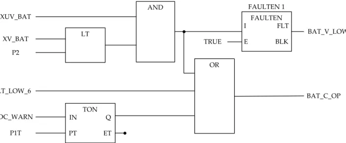
TON IN Q PT ET AND LT OR FAULTEN I FLT E BLK FAULTEN 1 XUV_BAT XV_BAT P2 VLT_LOW_6 DC_WARN P1T BAT_V_LOW BAT_C_OP TRUE
Figure 1. A small FBD program part of a battery control system showing the graphical nature of the language.
II. PRELIMINARIES
In the railway and avionics domain digital systems are controlled by software usually implemented on PLCs. In order to test PLCs described using FBD programs, we have to take into consideration the software usage particularities and the specific test purposes used for the generation of test suites. In the next section we briefly overview FBD programs and the TA semantics as a basis for describing our method and tool support.
A. FBD and IEC 61131 Component Model
PLCs are widely used in different control systems from nuclear power plants to traffic control systems. A PLC is an industrial real-time computer, integrated with a processor, a main memory, linked together by a common bus. On PLCs programs execute in a loop in which the iteration follows the “read-execute-write” semantics. This ensures that a PLC reads all inputs, executes the computation, and then writes to its output, all without interruption. FBD, a PLC programming language standardized by IEC 61131-3 [1], is widely used because of its graphical notations and its usefulness in applications with a high degree of data flow be-tween control components. An example of an FBD program depicting a small part of a Battery Control System is shown in Figure 1. An FBD program is composed of Functional Elements(FE) defined as Function Blocks (FB) and Functions (FU NC). Independent of the PLC choice language for IEC 61131-3, FU NCs and FBs are the base for a well structured and hierarchical FBD program. They are supplied by the manufacturer, defined by the developer, or predefined in a library. Both FE types cannot be recursive, i.e., self calling is not allowed. This is specific to the IEC 61131-3 standard because the amount of memory required
to hold the program at run-time can be determined off-line [1].
An FE can be defined as the following tuple: FE::= htypename, Port, Bi,
where typename is the name identifier, Port is the set ports,
defined as the union of input (IP) and output ports (OP) and B is the behavior description of the FE. For instance in Figure 1 the system consists of some basic logic, timer, state functionssuch asAND,OR, and a function block named
FAULTEN. A FU NC does not have any internal state and its output is determined only by the current inputs. This is the case forANDandLTin Figure 1. Differently,TONis an FB because it maintains an internal state and produces outputs based on this state and inputs.
Basically FBD programs and instrumentation points are shown in a circuit diagram fashion. Assume an FBD pro-gram defined as the following tuple:
FBDProgram::= hFE, V, P, Coni,
where FE is the set defined as the union of FU NC and FBinstances, V is the variables set, defined as the union of input (VI) and output (VO) variables, P is the parameters set, defined as the parameters used internally by the program, and Con is the set of connectors between all the functional elements (e.g., FB and FU NC). Con is a subset of the reunion of cartesian products and is defined as follows: Con::= (V I × FE.IP) ∪ (FE.OP × FE.IP) ∪ (FE.OP ×V O).
When activated and executed, the program in Figure 1 consumes one set of input data and then executes to completion. It should also be noted that depending on how FU NCs and FBs are defined, we can describe more complex
FBD programs. For example, a program can be ”populated“ with FBs, which can be similarly composed until very simple behaviors are directly described.
The IEC 61131 component model proposes a hierarchical software architecture for structuring and running any FBD program. This architecture specifies the syntax and seman-tics of a unified control software based on a PLC configu-ration, resource allocation, task control, program definition, function and function block repository, and program code [7], [8]. The PLC software is represented as a configuration that communicates with other IEC configurations of different PLC systems with well-defined component interfaces. Rep-resenting configurations, one or more resources are provided in order to support PLCs with features needed by the FBD program. The interfaces of a resource are described as input/output channels between the FBD program and the physical PLC defined environment. Covering the events in an FBD program, a task corresponds to a set of programs that either are executing periodically or upon the occurrence of a specified event [7]. An FBD program can have intra-program data flow communication and when activated, a program consumes one set of input data and then executes to completion. The PLC code is generated from the FBD program, which is used on a specific PLC and is the actual application code. For example, an application generator is utilized for the model-to-code transformation by assuming that each FE is translated to a C compliant program with its own thread of execution. More specifically, the FBD program code is mapped from FEs and program constructs into executable C code [8]. The resulting FBD program code is generally self contained and self-referencing.
We assume the PLC programs written in FBD to be verified, well-formed according to the IEC 61131-3 standard [1], and logically correct satisfying the following particular assumptions:
• A1: Execution Order. Each FE is executed in prede-termined order based on the control flow dependency. This predetermined order directly dictates the data dependency.
• A2: Port-Variable Assignation. Ports in Port and variables in V must be unique and should be connected in a well formed program according to the IEC 61131-3 standard.
• A3: Timing Annotations. To express timing con-straints within one FE, we need to correctly support timing elements according to IEC 61131-3 standard. B. Timed Automata
The timed automata model was introduced by Alur and Dill [9] and has gained a lot of attention as a suitable model for timed systems. We give here a short description for readers unfamiliar with this concept.
Let X be a finite set of clocks and B(X ) the set of guards, which are finite conjunctions of atomic guards of the form x./ n, where x ∈ X , n ∈ N, and ./ ∈ {<, ≤, =, ≥, >}.
A timed automaton (TA) over clocks X and actions Act is a tuple hL, l0, E, Ii where L is a finite set of locations, l0
is the initial location, E ⊆ L × B(X ) × Act × L is the set of edges and I : L → B(X ) assigns invariants to locations.
In the case of and edge hl, g, a, r, l0i ∈ E, we write l−−→ lg,a,r 0
where the label g is a guard of the edge, r is the data- or clock reset assignments of the edge, and a is the action of the edge.TAsemantics is defined as a transition system over states (l, u), with the initial state (l0, u0), where u0 assigns
all clocks in X to zero. Formally, there are two kinds of transitions:
• delay transitions: (l, u)−→ (l, u ⊕ d), where u ⊕ d isd the result obtained by incrementing all clocks of the automata with the delay amount d such that for any 0 ≤ d0≤ d, the invariant of l holds.
• discrete transitions: (l, u)−→ (la 0, u0), corresponding to taking an edge l −−→ lg,a,r 0 for which the guard g is
satisfied by u. The clock valuation u0of the target state is derived from reseting u according to updated r. A trace σ of aTAis a sequence of alternating delays and discrete transitions: σ = (l0, u0) a1 −→ (l1, u1) a2 −→ ... an −→ (ln, un).
Properties of TAcan be expressed as logical formulae in the Timed Computational Tree Logic (TCTL) [10]. In this paper we focus on properties of the form:
∃ ♦ p,
called reachability properties, where ∃ is the existential quantifier, and ♦ is the temporal operator. A reachability property states that there is a path in which the p location in the TAis reached.
A network ofTAT1k ... k Tnis a composition of nTAover
X and Act, synchronized actions (i.e., a! is complementary with a?) and shared (global) variables. We refer the reader to [11] for more information on the theory of TA.
III. TRANSFORMINGFUNCTIONBLOCKDIAGRAMS TO
TIMEDAUTOMATA
In this section, we describe how our approach enables the transformation of FBD programs to TA models, being one step away from test suite generation with the UPPAALtool. The model transformation, from an FBD program to a TA network is depicted in Figure 2. The transformation maps to a TA model all the interface elements FE, V, P, and Con alongside the existing timing annotations within the FBD program. This timing annotations are based on the specifications used from structure and behavioral elements
FBD Program FB F F F FB FBD Timed Automata F FB FB F F FBD Timed Automata FBD Timed Automata F FB FB F F PLC Cycle Scan &
Enviroment Structural and Interface Information FBD Timed Automata F FB FB F F R1 R2 R3 R4
PLC Cycle Scan & Enviroment
Structural and Interface Information
PLC Cycle Scan & Enviroment
Figure 2. Function Block Diagram to Timed Automata Transformation Process.
as defined in the FBD language. The timed behavior of an FBD program is defined as a TA, extended with data input and output variables. We first perform an automatic transformation of the FBD program to a TA model that obeys the read-execute-write semantics, hence preserving the semantics of FBDs without altering its structure. Next, we specify the execution of each FE in TA, and construct a complete PLC cycle and environment model by the parallel composition of local behaviors.
We describe a set of transformation rules which define the formal construction. The transformation process shown in Figure 2 is applied as follows:
1) R1 - FBD Program Declaration: We create a TA system description, place templates of FE instantiations, and list the composed TA network representing the FBD Timed AutomataFE1k ... k FEn.
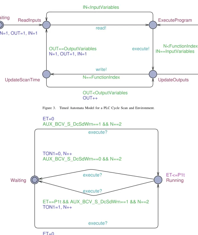
2) R2 - PLC Cycle Scan & Environment Generation: An FBD program is executed in a loop, in which the iteration follows the run-to completion semantics, corresponding to the TA model in Figure 3. We generate an automaton that contains a clock variable for modeling a delay between the cycles. A cycle starts when the automaton enters the ReadInputsstate and ends in UpdateScanTime state. When applying R2, V Is and V Os variable instances are defined. The IN and OUT counters represent the number of the variable and ensure that variables are evaluated one by one. For the FBD program to be testable, we also need to generate an environment model for controlling the program throughout all of its states.
3) R3 - FEs Execution Order Generation: We use the execution order of each FE automatically according to the general rules included in the IEC standard [1]. We use the notion of precedence to describe such dependencies on the convention of reading such FBD programs in a top-to-bottom, left-to-right fashion. For each FEs we assign a precedence priority to the corresponding TA model. In Figure 3 the counter N represents the number of the FE and
ensures that the FEs are executed one by one. After the last FEis evaluated, the counter is reset to repeat the scan cycle. 4) R4 - FEs Behavior Generation: For standard FEs we assign a TA behavior model. Each FE has its own logical execution and no internal concurrency, therefore it can be straightforwardly mapped to a TA model. We assign one TA model per FE (e.g., TON and FAULTEN in the FBD program shown in Figure 1). A rather straightforward model of the TON element with timing properties is shown as a TA model in Figure 4. The FBD program interacts with other TA via execute? action. TON is modeled by a standard time on timer that sets the output T ON1 to true if AU X _BCV _S_DcSdW rn input variable is true at least as long as the time P1T . Thus, we obtain an FB that returns different outputs despite having the same inputs over time. The timed behavior is specified using the TA semantics; in this procedure, we comply with the standard specification of the FB and the structural definition of the program. The TA model encapsulates the internal behavior with both functional and timing FBD properties. Also, every instance of the TON needs to contain all the variables listed in the declaration description. For this reason it is necessary to give each instance of the TON behavioral model a unique identifier.
As a result of the transformation we compose such local automata in parallel to a TA network FE1 k ... k FEn.
The purpose of the final phase of the transformation is to construct a target model by filling the TA with the corresponding FE behavior as explained in R4. Since FBD programs allows the use of behavioral notations, we exploit this, and specify the behavior by assigning a TA model to each element mapped from its corresponding FBD program.
IV. TESTGENERATION
In the context of testing FBD programs we assume that the test specification is given as a closed network of TA as shown in Figure 5. This model can be seen as two
OUT++ N=1, OUT=1, IN=1 N=1, OUT=1, IN=1 IN<InputVariables OUT<OutputVariables N<FunctionIndex OUT==OutputVariables N==FunctionIndex IN==InputVariables UpdateOutputs UpdateScanTime ExecuteProgram ReadInputs Waiting read! write! execute!
Figure 3. Timed Automata Model for a PLC Cycle Scan and Environment.
ET=0 TON1=1, N++ execute? execute? execute? Waiting TON1=0, N++ Running ET=0 AUX_BCV_S_DcSdWrn==0 && N==2 ET<=P1t execute? AUX_BCV_S_DcSdWrn==1 && N==2
ET==P1t && AUX_BCV_S_DcSdWrn==1 && N==2 AUX_BCV_S_DcSdWrn==0 && N==2
Figure 4. Timed Automata Behavioral Model for a TON element.
sub-networks, one modeling the FBD Program and the other one modeling its PLC Cycle Scan. The program operates in a specific environment that takes into account the A1-A3 assumptions. Obviously we can consider a com-pletely unconstrained environment that allows all possible
interactions between the TA network elements. For all environments we assume that the test specification is used to control the FBD diagram via read?, execute?, and write! actions.
FBD Program
read?
PLC Cycle Scan & Enviroment
execute?
write!
Figure 5. Test TA Network for a FBD Program.
UPPAAL is a model-checker using TA as a modeling language1. It supports dense clocks and different data types like bounded integers and arrays. The verification language supports properties such as safety, liveness, and reachability. We describe here a methodology to produce test sequences for FBD programs using UPPAAL, making use of UPPAAL’s ability to generate diagnostic traces witnessing a submitted reachability property [12]. Currently UPPAALsupports three options for diagnostic trace generation: some trace leading to a goal state, the shortest trace with the minimum number of transitions, and fastest trace with the shortest time delay. Whereas UPPAAL is a viable tool for model checking, it is
tedious and not tailored to test suite generation in practice. We demonstrate how to automatically generate test cases from an FBD program described in TA. Specifically we show how to generate test suites for FBD programs using specific test requirementsor from various coverage criteria.
Let us assume a TA network model of an FBD program together with its PLC cycle scan and environment shown in Figure 5. A test sequence produced by the model checker for a given reachability property defines the sequence of actions executed on the FBD test specification. An example of a diagnostic trace has the following form:
(FBD0, PLC0) A1 −→ (FBD1, PLC1) A2 −→ ... An −→ (FBDn, PLCn),
where (FBDk, PLCk) are states of the FBD program and PLC
cycle scan with environment constraints, respectively, and Ak
are either internal synchronization actions, time-delays or read?, execute?, and write! global synchronizations. For our test specification the sequence represents only the global synchronizations shown in Figure 5. From the PLC cycle scan point of view the trace is obtained only by taking into account the observable actions read?, execute?, and write!.
Generation of test suites for an FBD program starts with the process of first manually formulate a set of informal test
1The UPPAALtool is available at www.uppaal.org.
properties and continues with formalization of these such that the model can be used to generate test suites for each test property. In this context, a test requirement is a specific test property that the tester would like to formulate. For using the test generation capability of the UPPAAL model-checker, the test property must be formulated using the CTL logics and checked by the test specification.
For the example in Figure 1, two test properties can be directly transformed into simple CTL reachability properties:
• TP1: The Battery Contactor is tripped due to low battery.
• TP2: Battery Contactator is open when Battery Voltage is valid.
For example TP1 can be formulated as the following CTL reachability property:
∃ ♦ plc.UpdateScanTime and BAT_V_LOW==1,
where the property can be read as follows: there exists an execution path such that, eventually, the PLC cycle scan automaton enters location UpdateScanTime and the battery is low. Generating a diagnostic trace based only by using observable actions results in the following test sequence: (IN1, ..., IN6) read! −−−→ (FE1, ..., FE6) execute! −−−−→ (OUT1, OU T2) write! −−−→ .
A. Test Suite Generation
Obviously a single test case cannot be obtained for every test purpose or criterion. By using PLC scan cycle shown in Figure 3 we allow the test suite to be implemented as one or more test sequences separated by resets. To introduce resets in the model, we allow the PLC scan cycle to perform a reset which is encoded by adding a reset transition leading to the initial ReadInputs location. On this transition all variables and parameters (excluding encoded variables used
for coverage-based test suite generation) are reset to their default value. This reset is hardcoded into the PLC scan cycle for any modeled FBD program in UPPAAL, being an atomic communication between all the TA models.
B. Coverage-based Test Suite Generation
There is often the case that we are interested in a test suite that ensures that the FBD program is covered in several ways. This ensures that a certain level of thoroughness has been achieved in the test generation process. Structural test criteria are used for evaluating the adequacy reached by a certain test suite. A test criterion is formulated using so called coverage items. These items should be exercised during testing in order for the criterion to be satisfied. For example, in node coverage, nodes are coverage items [13]. Usually, testers describe the extent to which a criterion is exercised by using the ratio between the number of coverage items exercised in testing and the overall number of coverage items in the software under test. The work by Hessel et al. [14] explains how to apply coverage criteria to TA models, but is based on different structures and state verification methods from this work. Here we give the details of our FBD model coverage approach on how to automatically generate test suites using coverage analysis. A large number of cov-erage criteria has been investigated in last couple of years, such as statement, transition, definition-use coverage, and MCDC, each with its own merits and application domain. We propose the usage of coverage analysis directly on the FBD programs. We describe next the following structural coverage criteria:
• FC: Function Coverage. It analyzes FEs in an FBD program. Full FC indicates that each FE in a program has been executed at least once. To determine the number of execution paths traversed by the program we introduce an auxiliary boolean variable fiin the TA
model for each FE to be covered and formulate the following reachability property:
∃ ♦ ( f0== 1 and f1== 1 ... and fk== 1).
• DC: Decision Coverage. It analyzes every decision points in the FBD program. Full DC indicates that each FE in a program has taken every outcome at least once. We implement a mechanism to facilitate this by specifying a set of DC parameters. We annotate the TA model with an auxiliary boolean variable vi for
each decision di to be covered. For every edge with
destination di: l g,a,r
−−→ di, vi is added to r assignment.
The reachability property for full DC will require that all vi to be true.
• CC: Condition Coverage. It analyzes FEs that output the logical combination of their inputs. A test suite achieves full CC when it causes each input in to each
instance of an FE in the FBD program and each
con-dition ci on a transition to be true at least once during
the execution, and false at least once. For generating test sequences for CC we check whether an auxiliary boolean variable v0i is covered for each condition in the program as follows:
∃ ♦ (c0== 1 and c1== 1 ... and ck== 1). V. EXPERIMENTS
In the previous section we presented our approach towards automatically generating test suites for FBD programs. In the following, we show some relevant experiments in order to show the performance of this technique and the tool support. We take into account quantitative measures related to model-checking including test suite length, generation time, and memory usage.
In our work we make use of the PLC software develop-ment tools for the MITRAC Train Control and Managedevelop-ment System (TCMS) provided by Bombardier Transportation AB within the ATAC research project [15]. TCMS is a distributed system, built on open standard IP-technology that allows easy integration of control and communication functions for high speed trains. The Central Computing Units (CCUs) contain all FBD programs controlling the train. The PLC development tools used for developing these programs are based on the MULTIPROG software. For the rest of the paper we will refer to FBD programs created using PLC development tools used for TCMS. The TCMS involves over 800 FBD programs and approximately 122,000 lines of generated C code. In our experiments we used only a part of the TCMS system. More precisely, the battery control was used as the system under test.
In the next next sections we give an overview of the results and experiences we had in building the TA model and generating test suites from it. We touch on the practical lessons learned for the system below, while we do not give tips to the practitioner here.
A. Train Battery Control System
The Battery Control System (BCS) is part of the TCMS distributed system which contains over 30 FBD programs and 5,000 lines of generated C code. The system supplies the units on the train with power when auxiliary power is not present. When auxiliary power is present, the batteries are charged. There are two completely redundant battery buses with two redundant batteries (including chargers) connected to each bus. Every unit can be supplied via any bus. The battery chargercharges and supervises the battery and sends information to TCMS over the IP network. The main battery contactor connects the battery to the battery buses when closed and load shed contactors supply loads of different priority to the batteries.
A TA network that modeled the entire BCS was devel-oped and subsets were extracted for testing FBD program
Table I
STANDARDTIMEDAUTOMATAMODELS DEVELOPED FOR THEBCS
SYSTEM
Library Standard Models Manufactured Supplied Models ARITHMETIC (ADD, MUL,
SUB, DIV, MODE)
FAULTEN
BITWISE (AND, OR, XOR, NOT)
FAULTDLY
BITWISE (AND, OR, XOR, NOT)
OSC T
SELECTION (SEL, MAX, MIN, LIMIT, MUX)
MEM1 R
COMPARISON (GT, GE, EQ, LT) DELAY BISTABILE (SR, RS) TOOGLE EDGE (SR, RS) MEM1 BO COUNTERS (CTU, CTD, CTUD) DELAY BO
TIMERS (TP, TON, TOF, RTC) OSC
requirements; however, the model is used as a relative small system, but well beyond the scale of academic exercises. We concentrated on the standardized PLC functionality and modeled manually in UPPAALtool over 35 library detailed models compliant with the IEC standard and MITRAC supplied library. A list of the modeled TAs is found in Table I. For more information on the standard PLC functions please refer to [1].
We are using the UPPAALmodel-checker2for generating test suites. The tools for building, editing, and analyzing the models are included in the UPPAALmodel checker.
B. Results and Evaluation
The experiments reported here are based on a model of a BCS starting from the original program stored in an XML-document, which is used for the transformation to the UPPAAL input language 3 as described in Section III. We developed a reader and parser to analyze the programs and elements of the FBD standard language. In this way we deal only with programs that are strictly IEC 61131-3 standard compliant. We use the transformation tool to automatically derive a TA model of the BCS. To see how our technique performs, we generate test suites based on some train-related test properties. The train is in many ways the ultimate test environment since it is the environment where BCS will ultimately end up in. However, the train should be used as little as possible since it is so expensive to use. The generated test suites are executed on the softTCMS 2We are using the following version of the UPPAALmodel checker: 4.1.7
(rev. 4934) under MAC OS X version 10.7.4
3The XML syntax describing the element definitions
from the Document Type Definition is available at http://people.cs.aau.dk/ adavid/utap/syntax.html
Table II
TEST SEQUENCE DERIVATION ON THEBCSSYSTEM
Test Properties Generation Time Test Suite length Memory
TP1 0.09 s 48 4 MB TP2 0.09 s 50 5 MB TP3 0.07 s 50 4 MB TP4 0.03 s 38 5 MB TP5 0.03 s 40 4 MB TP6 0.03 s 38 6 MB
platform, developed by CrossControl 4. This allows us to run our test suite on the simulated environment, without the need to change the PLC code and platform. To perform the actual testing process, a complete test interface was built that supports automated generation of tests. This test interface and the transformation are independent of UPPAAL
and could be used in similar model checkers supporting other automata models.
UPPAAL takes as input the FBD program together with a test requirement, and generates ready-to-use test suites. The test suite is ready to be executed by a test execution environment. Testing FBD programs is done in isolation from the rest of the TCMS software in a controlled simulated environment, making the component tests a good target for coverage-based test generation and therefore a potential benefit to automatic evaluation of test cases.
The results, listed in Table II, show that this particular example scales well in terms of generation time (in seconds), memory usage (in MB), and the test suite length (in number of transitions in the TA model)5. As described in Section IV the test suites are generated from different test properties transformed into simple CTL reachability properties. TP1-TP6 test properties are included in the BCS unit test speci-fication, provided by TCMS test experts. The properties are briefly described in Section IV and Table III.
We made no simplification of the TA model, and we used test specifications prepared by testing professionals in entirety. The test suites in Table II are generated by using only the observable actions. Each test suite in Table II is a set of two test cases that begins with the ReadInputs state and ends with the UpdateScanTime state.
We also generated coverage-based test suites which en-sures that BCS is covered in a certain way. Here we make use of the FBD structural criteria defined in Section IV. Table IV shows the generation times (in seconds) for test suites generated from different coverage criteria and the length (number of transitions) of the generated test suite. We notice that DC and CC require many interactions (trace 4softTCMS simulation platform implements mock libraries specific to
the PLC platform and simulates the hardware and communication devices on the actual train.
5Experiments were executed on a machine with 2.4 Ghz Intel Core i5
Table III
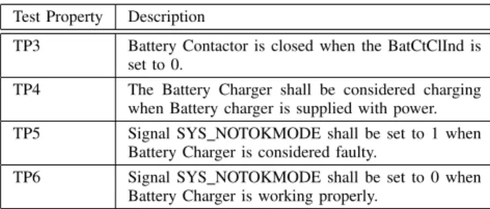
EXAMPLE OFTESTPROPERTIES FORBCS UNITTESTSPECIFICATION
Test Property Description
TP3 Battery Contactor is closed when the BatCtClInd is set to 0.
TP4 The Battery Charger shall be considered charging when Battery charger is supplied with power. TP5 Signal SYS NOTOKMODE shall be set to 1 when
Battery Charger is considered faulty.
TP6 Signal SYS NOTOKMODE shall be set to 0 when Battery Charger is working properly.
Table IV
RESULTS FOR VARIOUS COVERAGE CRITERIA ON THEBCSSYSTEM
Coverage Criterion Generation Time Test Suite length
FC 0.15 s 49
DC 0.53 s 102
CC 0.47 s 100
of length up to 102) and contains four test cases. In contrast to the results in Table II, the generation time for coverage criteria are between 0.15 and 0.531 seconds.
Although this is not surprising, it can be seen that is much cheaper to compute test suites for test purposes than obtaining coverage for FBD programs. Obviously the PLC cycle scan and environment can pose restrictions on our results. This means that the generation of test suites has to evaluate all possible behaviors in case of a more unre-stricted environment resulting in more expensive test suites with regard to generation time and used memory. Still the experimental results show how our test case generation for FBD programs scale up for different models and coverage criteria.
VI. RELATEDWORK
Previous contributions in testing of FBD programs range from a simulation-based approach [16] to verification of the actual FBD program code [17]. The technique in [17] is based on Petri Nets models and supports the entire development process. In comparison to our work, they are not coping with the internal structure of the PLC language aspects. It is our opinion that testing FBD programs can be complemented by using model-checkers as presented in this paper.
Similar to our work and strictly related to lower levels of testing, there have been some attempts to focus on FBD program testing [18], [19]. These works are focusing on structural testing techniques and are proposing a solution based on the logical aspects of the FBD program.
Also related to this work but outside the PLC-based software development community, the most notable efforts has been focusing on test coverage for data flow languages. For example, for the Lustre language there are contributions
[20], [21], [22] describing an activation condition concept that can be used when data flow from an input edge to an output edge may occur.
Research of the usage of model-checkers for verifying and testing FBD programs is not new. Soliman et al. [23] are using UPPAAL model checker for verification of FBD safety applications including the safety libraries. Silva et al. [24] are generating TA models from FBD programs and are testing their specifications using UPPAALTRON tool. These two approaches are using a different transformation process and are considerably different in the way of formulating test properties. In contrast to the online model-based testing approach used in [24] we are generating test suites for offline execution on the system under test.
However, to our knowledge, not much theoretical and ex-perimental data is available about the usage of model-based test generation for realistic PLC industrial sized systems. More case studies are needed to form a strong methodology and support for improving FBD program testing.
VII. CONCLUSIONS
We presented an approach to generate test suites for PLC software using UPPAAL model checker. Therefore, a transformation from PLC software written in FBD language to a TA model has been introduced, which allows also timing informations into the test suites. For the translation of an FBD program into a TA model, a set of rules have been presented. On the basis of this model, a model checker has been used for generating consistent test suites.
The applicability of our approach has been demonstrated on a train control and management system used in the railway industry. The test generation technique and the coverage criteria used have industrial validity as complete test suites have been generated for an industrial application for unit level testing of FBD programs. We developed a prototype tool to extract the FBD programs, to translate them into a TA model, and to enable test suite generation by using a model checker. We believe that this technique is useful for transforming and testing component models of other industrial safety-critical embedded systems similar to PLCs.
VIII. FUTUREWORK
We are currently investigating this approach on a larger design process. In addition, we want to extend the scope of the test generation to enable support for integration and system level testing. We believe that using the right model-based test generation technique for PLC software constitutes the necessary basis for a framework used in automated test generation and verification. By using a model for both requirements of the system and coverage criteria, test results can be thoroughly evaluated based on how precise and detailed is the system is modeled.
IX. ACKNOWLEDGMENTS
This work was supported under grant agreement number 2011-01379, from VINNOVA, the Swedish Governmental Agency for Innovation Systems, within the ATAC project. Special thanks to Cristina Seceleanu and Raluca Marinescu from M¨alardalen University for the valuable feedback.
REFERENCES
[1] K. John and M. Tiegelkamp, “IEC 61131-3: ming Industrial Automation Systems: Concepts and Program-ming Languages, Requirements for ProgramProgram-ming Systems, Decision-Making Aids,” 2010.
[2] W. Bolton, “Programmable Logic Controllers.” Newnes, 2009.
[3] M. Younis and G. Frey, “Formalization of existing PLC programs: A survey,” Proceedings of CESA, pp. 0234–0239, 2003.
[4] G. Hassapis, “Soft-testing of Industrial Control Systems Pro-grammed in IEC 1131-3 languages,” ISA transactions, vol. 39, no. 3, pp. 345–355, 2000.
[5] M. Hutchins, H. Foster, T. Goradia, and T. Ostrand, “Railway Applications - Communications, Signaling and Processing Systems - Software for Railway Control and Protection Sys-tems,” Electrical equipment and systems for railways, 2011. [6] K. Larsen, P. Pettersson, and W. Yi, “UPPAAL in a Nut-shell,” International Journal on Software Tools for Technology Transfer (STTT), vol. 1, no. 1, pp. 134–152, 1997.
[7] M. ¨Ohman, S. Johansson, and K. ˚Arz´en, “Implementation As-pects of the PLC standard IEC 1131-3,” Control Engineering Practice, vol. 6, no. 4, pp. 547–555, 1998.
[8] J. Thieme and H. Hanisch, “Model-based Generation of Modular PLC code using IEC61131 Function Blocks,” in Pro-ceedings of the IEEE International Symposium on Industrial Electronics, vol. 1. IEEE, 2002, pp. 199–204.
[9] R. Alur and D. Dill, “Automata for Modeling Real-time Systems,” Automata, languages and programming, pp. 322– 335, 1990.
[10] R. Alur, C. Courcoubetis, and D. Dill, “Model-checking in Dense Real-time,” Information and computation, vol. 104, no. 1, pp. 2–34, 1993.
[11] R. Alur, “Timed Automata,” in Computer Aided Verification. Springer, 1999, pp. 688–688.
[12] A. Hessel, K. Larsen, M. Mikucionis, B. Nielsen, P. Pet-tersson, and A. Skou, “Testing Real-time Systems using UPPAAL,” Formal Methods and Testing, pp. 77–117, 2008.
[13] H. Zhu, P. Hall, and J. May, “Software unit test coverage and adequacy,” ACM Computing Surveys (CSUR), vol. 29, no. 4, pp. 366–427, 1997.
[14] A. Hessel, K. Larsen, B. Nielsen, P. Pettersson, and A. Skou, “Time-Optimal Real-Time Test Case Generation Using UP-PAAL,” Lecture Notes in Computer Science, Formal Ap-proaches to Software Testing, pp. 114–130, 2004.
[15] ATAC- ITEA2 Consortium. (2012). [Online]. Available: http://www.testautomation.fi/atac-dev/
[16] S. Richter and J. Wittig, “Verification and Validation Process for Safety IC Systems,” Nuclear Plant Journal, vol. 21, no. 3, pp. 36–36, 2003.
[17] L. Baresi, M. Mauri, A. Monti, and M. Pezze, “PLCTools: Design, Formal Validation, and Code Generation for Pro-grammable Controllers,” 2000 IEEE International Conference on Systems, Man, and Cybernetics, vol. 4, pp. 2437–2442, 2000.
[18] E. Jee, J. Yoo, S. Cha, and D. Bae, “A Data Flow-based Structural Testing Technique for FBD Programs,” Information and Software Technology, vol. 51, no. 7, pp. 1131–1139, 2009.
[19] E. Jee, S. Kim, S. Cha, and I. Lee, “Automated Test Cov-erage Measurement for Reactor Protection System Software implemented in Function Block Diagram,” Computer Safety, Reliability, and Security, pp. 223–236, 2010.
[20] A. Lakehal and I. Parissis, “Automated Measure of Structural Coverage for LUSTRE Programs: a Case Study,” Automation of Software Test, 2007. AST’07. Second International Work-shop on, pp. 12–12, 2007.
[21] ——, “Lustructu: A Tool for the Automatic Coverage Assess-ment of Lustre Programs,” 16th IEEE International Sympo-sium on Software Reliability Engineering, 2005., pp. 10–pp, 2005.
[22] ——, “Structural Test Coverage Criteria for Lustre Pro-grams,” in Proceedings of the 10th international workshop on Formal methods for industrial critical systems. ACM, 2005, pp. 35–43.
[23] D. Soliman, K. Thramboulidis, and G. Frey, “Function Block Diagram to UPPAAL Timed Automata Transformation Based on Formal Models,” Information Control Problems in Manu-facturing, vol. 14, no. 1, pp. 1653–1659, 2012.
[24] L. da Silva, L. de Assis Barbosa, K. Gorgˆonio, A. Perku-sich, and A. Lima, “On the Automatic Generation of Timed Automata Models from Function Block Diagrams for Safety Instrumented Systems,” 34th Annual Conference of IEEE Industrial Electronics, 2008. IECON 2008., pp. 291–296, 2008.