V¨
aster˚
as, Sweden
Thesis for the Degree of Master of Science in Engineering - Robotics
30.0 credits
REDUNDANT FIRMWARE TEST
SETUP IN SIMULATION AND
HARDWARE: A FEASIBILITY STUDY
Per Ekstr¨
om
pem14001@student.mdh.se
Elisabeth Eriksson
een13011@student.mdh.se
Examiner: Masoud Daneshtalab
M¨
alardalen University, V¨
aster˚
as, Sweden
Supervisors: Mohammad Loni
Alessandro Papadopoulos
M¨
alardalen University, V¨
aster˚
as, Sweden
Company supervisor: Bjarne Johansson
ABB Embedded Systems, V¨
aster˚
as, Sweden
Abstract
A reliable embedded real-time system has many requirements to fulfil. It must meet target deadlines in a number of situations, most of them in a situation that puts heavy stress on the system. To meet these demands, numerous tests have been created which test the hardware for any possible errors the developers might think of, in order to maximise system reliability and stability. These tests will take a lot of time to execute, and as system complexity grows, more tests are introduced leading to even longer testing times. In this thesis, a method to reduce the testing time of the software and, to a lesser extent, the hardware is examined. By using the full system simulator Simics, an existing industry system from ABB was integrated and tests were performed. A proof of concept test suite for automatic redundancy tests was also implemented. By looking at the test results, it was concluded that the method shows promise. However, problems with the average latency and performance troubles with Simics shows that more work must be put into this research before the system can be run at full speed.
Keywords: Hardware-In-the-Loop, HIL, Simulation, Automated testing, Simics, Wind River, Redundancy, Latency
Acknowledgements
While the main work of the thesis is performed by us the authors, we have not been the only ones involved in this project. We would like to take this opportunity to thank a few people for their help and support. Our company supervisor Bjarne Johansson has been an excellent supervisor, never afraid to proofread the thesis paper and helping us understand the ABB systems properly. Like-wise, our supervisors Mohammad Loni and Alessandro Papadopolous from Mlardalen University were a very big help with their knowledge of the academic writing process. Jakob Engblom and other Intel/Wind River employees gave invaluable feedback and support with everything related to Simics, allowing us to move forward at a very fast pace. The people at ABB Control Technologies also provided very good support throughout the thesis, not to mention giving us this opportunity to analyse their products in the first place. Finally, we would like to thank our friends and families for their support. We could not have done it without you.
Table of Contents
1 Introduction 5
1.1 Problem formulation . . . 6
1.1.1 The Select I/O subsystem . . . 6
1.1.2 Purpose . . . 6
1.1.3 Hypothesis . . . 7
1.1.4 Research questions . . . 7
1.2 Thesis Outline . . . 7
2 Background 8 2.1 Automated tests in a simulated environment . . . 8
2.2 The ABB AbilityTM System 800xA series . . . . 9
2.3 Redundancy . . . 9
2.3.1 Modular voting redundancy . . . 9
2.3.2 Standby modular redundancy . . . 10
2.3.3 Load balancing redundancy . . . 11
2.4 Hardware-in-the-loop (HIL) . . . 11
2.5 Hardware simulation in Software . . . 11
3 Related work 13 3.1 Current research . . . 13
3.1.1 Simulation and Emulation . . . 13
3.1.2 Hardware in the loop . . . 13
3.1.3 Redundancy and HIL . . . 14
3.2 Current industry standards and frameworks . . . 14
3.2.1 Wind River – Simics . . . 14
3.2.2 National Instruments – LabVIEW . . . 15
3.2.3 Mathworks – Simulink and Speedgoat . . . 16
3.2.4 Scicos . . . 16
3.2.5 Honourable mentions: ROS, YARP and RSB . . . 16
4 Method 17 4.1 Implementation plan . . . 17 4.2 Expected results . . . 17 5 Implementation 18 5.1 Target Hardware . . . 18 5.2 Simulation . . . 19 5.2.1 Component analysis . . . 19 5.2.2 Simulation setup . . . 20 5.3 Connecting Hardware . . . 20 5.4 Simulated components . . . 21 5.5 Software . . . 22 5.5.1 The Kernel . . . 22
5.5.2 The FCI firmware . . . 22
5.5.3 Redundancy link . . . 23 5.5.4 PROFINET . . . 23 5.5.5 Modulebus . . . 23 6 Experimental results 24 6.1 Use cases . . . 24 6.2 Test 1: Latency . . . 25 6.3 Test 2: Redundancy . . . 26 6.4 Test 3: Scalability . . . 27 6.5 Results . . . 28 6.5.1 Latency results . . . 28
6.5.2 Redundancy results . . . 28 6.5.3 Scalability results . . . 28 7 Discussion 30 7.1 Mixed advantages . . . 30 7.2 Timing issues . . . 30 7.3 Integration in simulation . . . 31 7.4 Experiment results . . . 31 7.5 Simulation experiences . . . 32 7.6 Future Work . . . 33 7.6.1 Timing . . . 33 7.6.2 Integration . . . 33 7.6.3 Scalability . . . 34 8 Conclusions 35 8.1 Mixed Redundancy Testing . . . 35
8.2 Suitability . . . 35
8.3 Integration . . . 35
8.4 Scalability . . . 35
8.5 Final thoughts . . . 35
References 38 Appendix A Redundancy test 39 A.1 redmockup.c . . . 39
A.2 Test battery . . . 40
A.2.1 test setup.simics . . . 40
A.2.2 automated test.simics . . . 41
Appendix B Scalability test 42 B.1 mockload.h . . . 42
B.2 mockload.c . . . 42
Abbreviations list
ABB ABB (Asea Brown Boveri) Ltd
BSP Base System Package
CPU Central Processing Unit
DAQ Data Acquisition
DCS Distributed Control System
DPC Deferred Procedure Call
EA Ethernet Adapter
FCI Field Communication Interface
FPGA Field Programmable Gate Array
GIO General Input / Output
GPU Graphics Processing Unit
HAL Hardware Abstraction Layer
HIL Hardware-in-the-Loop
I/O Input / Output
ISR Interrupt Service Routine
ITP Interrupt to Process
MIPS Microprocessor without Interlocked Pipeline Stages
MPSoC Multi-Processor System-on-a-Chip
NVRAM Non-Volatile Random-Access Memory
OS Operating System
OSI Open Systems Interconnection
PC Personal Computer
PCI Peripheral Component Interconnect
PM Processing Module
QSP Quick Start Platform
RAM Random Access Memory
ROS Robotic Operating System
RSB Robotics Service Bus
RTOS Real-Time Operating System
SAM Safety Adressing Module
SCADA Supervisory Control- And Data Acquisition
SCM Signal Conditioning Module
SIL Safety Integrity Level
TAP Terminal Access Point
UART Universal Asynchronous Receiver/Transmitter
USB Universal Serial Bus
VHDL VHSIC Hardware Description Language
VI Virtual Instrument
1
Introduction
Since the advent of the steam engine and the availability of cheap energy, the industrial sector has undergone a massive automation process that is still active to this very day. While electricity has replaced steam and microcomputers have added both intelligence and utility to machines, the same basic concept has remained unchanged. By enabling the machines to automate bigger and more complex tasks, the human workforce can focus on doing less repetitive and mundane tasks, and further on the creative and inspiring ones.
Today, the industry is manufacturing their products in large, complex machines that consist of many different parts and are managed at breakneck speed by computers. To keep track of all the components, a communication network of embedded systems are utilised to control every last detail, from drilling and cutting to packaging and assembly. These networks are usually built to meet the strict demands of reliability and availability, but hardware capable of reaching such high standards does come at a high price. Not only does the network equipment itself have to be tested, every device connected to the network has the same stringent demand.
The industry sets these demands because one single modern and fully automated factory may be able to output several thousand products in a single day. If those factories should grind to a halt, that is several thousand products not produced and more importantly, not sold. If the supply should dry up, then obviously there can be no sales, since the factory will not be able to deliver the actual product. Depending on the sales price of the item and type of item, this can in the worst case translate to several millions of dollars of revenue lost each hour the system is down[1,2]. That is why the equipment must be designed, engineered and built to be as durable as possible.
Such high standards require a very thorough testing procedure, and by its very nature, that procedure takes a lot of time to execute. Whenever a new version of the equipment is scheduled for release, the entire system for both hardware and software must undergo several layers of testing, and should the equipment fail any of the tests in any of these stages the software and hardware must be changed and then retested. Worse, such a procedure can, depending on the error and fix involved, push the testing back to a previous layer, or even from the beginning. Even if a lot of these tests can be automated, they still will take time, and a lot of these tests can easily involve hundreds of different embedded systems and hardware units - all of which have to be manually assembled and tested, and manual switches often having to be flipped.
Most hardware systems today also utilise a software solution running on top of a micro controller chip, and by doing so manages to perform the multiple tasks of what was once the job of a single electrical system. This has the benefits for a much cheaper manufacturing price, as well as a much smaller physical system size. While this method of building systems has many benefits, the software in and of itself require testing as well, and a lot of it.
Because of the time-consuming nature of this testing, many industrial companies have opted to attempt to automate the process by emulating their full hardware environments in a simulated environment, with various degrees of success. Modern tools such as Simics, LabVIEW and Simulink are all examples of such frameworks that can help to test and find issues, both in code logic and timing assumptions.
The foundation of this thesis was to explore a method whereupon a physical hardware unit is connected to an equivalent simulated hardware unit by virtual interfaces and buses, thus creating a redundant pair of simulated and physical hardware. By examining the usefulness of this method it could be possible to decrease time spent testing for a diverse set of issues, and therefore de-crease turnover times and reduce the time to release a product to the market considerably. Other additional benefits would be to allow software developers to start months in advance, as well as perform white box testing on the software in the simulated portion.
The thesis utilised existing hardware systems provided by ABB, and attempted to simulate these systems. Unfortunately the simulation of the provided hardware could not be finished in time, and latency issues prevented the method to be fully explored. In the end, some data was collected and the method shows some promise, but more research must be performed in order to validate the findings.
1.1
Problem formulation
The aim of this thesis to explore the current state-of-the-art for simulated hardware frameworks and to evaluate their utility when it comes to automatically testing the redundancy functionality of an embedded component designed for hot standby redundancy, as described in section2.3.2. It also aims to explore what happens when a real redundant hardware component is connected to a virtual network and what happens when its redundant counterpart is inside the virtual network, and the physical unit is connected to the bus.
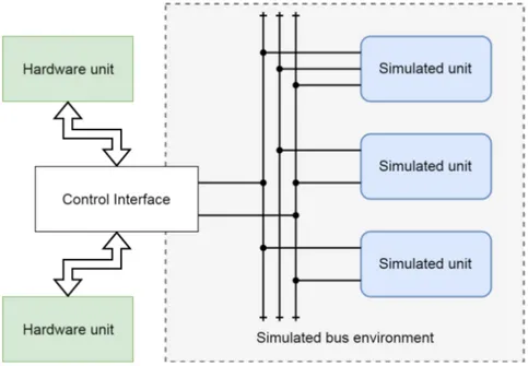
In order to do so, a mixed system of simulated and physical hardware will be attempted to be built, where virtual buses and virtual components will be built using already existing simula-tion software, with the opsimula-tion of connecting a hardware bridge interface to the simulated buses, according to figure1.
Figure 1: An overview of the desired test environment. The virtual environment will communicate through virtual buses and there should also be a control interface that allows real hardware to connect to and interact with any (or none) of the virtual buses available.
1.1.1 The Select I/O subsystem
Since it is much easier to test something that already exists, this thesis will set out to do a case study about a system from ABB that is a prime candidate for this kind of conversion. The system is called Select I/O and is described in more detail in section2.2 and section5.1.
Simulating the full Select I/O environment with all the bells and whistles as advertised would be a very large undertaking as a master thesis, given the short time the thesis project has to work with and the unfamiliarity with the development environment used at ABB. There are three different communications protocols (PROFINET, Modulebus, SCM link) and five different types of embedded system components involved. By choosing and focusing on a single component to model, it is much easier to create a simulation that may answer the questions asked. Therefore, a component analysis has been performed in section 5.2 which significantly narrowed down the simulation targets to just two protocols and a single embedded component.
1.1.2 Purpose
The purpose of this thesis is to evaluate different frameworks suitable for simulated and physical hardware redundancy testing, to build a proof-of-concept automated redundancy test battery using the said framework and to examine the viability of a simulated and physical hardware combination as explained above.
1.1.3 Hypothesis
Given a simulation of hardware, it should be possible to connect the simulation to real hardware. Therefore, it should be possible to run a redundant system with one simulated and one physical equivalent component. By connecting a simulated component with a physical component, it should be possible to create a redundant system that allows for more test vectors, and also reduce testing times by utilising automated testing frameworks.
1.1.4 Research questions
Given this problem formulation, four distinct research questions arise. These will be attempted to be answered through testing and running experiments, as well as some argumentation.
1. Mixed redundancy testing - How will a mixed environment of simulated and physical hardware be different from a purely simulated or hardware approach, and why would that be an advantage?
2. Suitability - How can a mixed environment testing benefit the testing process, and why? How much of an advantage does it bring over a full hardware or full software environment? 3. Integration - How difficult will it be to integrate already existing components to a mixed
environment, both in hardware and software?
4. Scalability - How many different hardware units can be simulated at the same time?
1.2
Thesis Outline
In this section, a brief introduction to the thesis has been given, as well as the problem formulation, thesis purpose and research questions. This is followed by a more in-depth description of the problem in section2as well as a brief description of current methods in section3.1and an overview of framework options in section3.2. Then follows a description of the method in section4, before going into the actual work.
In section 5, the actual implementation details are described, the problems found with the various parts and what was done to deal with them. This is the main work of the thesis.
Wrapping this up, there are a few closing sections. In section 6, the experimental testing is explained and the results are presented. This is then followed by a lengthy discussion of the results and findings in section7and finally, the conclusions to these are given in section8.
2
Background
Hardware virtualisation and emulation has existed in one form or another ever since the 1960s, but it truly gained traction after 1989 when it was discovered how to transfer the information in a ROM chip to a file. From then on, more and more sophisticated solutions emerged and as computer technology evolved virtualisation and emulation slowly grew to the point seen today.
At the same time, the demands on reliability testing have increased tremendously in the in-dustry. This is not surprising given the complexity of current systems. While the demands for safety and reliability are increasing every year, the main reason testing times increase is because machines have gotten a whole lot more complex and perform a bigger part of manufacturing than ever before. Figure2explains this problem in slightly more detail.
Figure 2: An example overview of the time distribution for the hours spent on a simpler (blue) and more complex (purple) embedded system with the same features. The relative time spent in testing, debugging and certification grows with the complexity of the system.
2.1
Automated tests in a simulated environment
Given this background, it should come as no surprise that there is a lot of incentive for automating the tests and move them to a virtual environment in order to reduce the turnover time. Since software is so much easier to modify than hardware, this virtual testing can get rid of most system-level defects before they even touch the actual hardware test rig, thus providing a much faster development iteration cycle. This can give quite a few benefits like reducing the time a product comes to the market, lessen the time to find bugs and increase the number of test cases that can be run in the same time frame [3,4].
Emulating such a complex environment in the past often required the computational resources of a mainframe computer, but thanks to new discoveries and advancements within the field of computer science, new tools have also emerged. Today, an embedded environment complete with bus traffic can be emulated on a relatively modest workstation.
In such a simulator, the lower physical layers are rarely interesting to emulate. What is instead interesting is to see how algorithms grow and develop. Therefore, most bus traffic is emulated on a frame-accurate level on the second or even third layer of the OSI communications stack. Of course this does not exclude the use of fault injections, disconnecting cables or corrupt frames, but these specific events will only happen if explicitly called upon. Otherwise, the lower layers are assumed to be fault-free.
The biggest advantage to having these complex, simulated environments is due to the ease it lends itself to automated testing. In it’s most basic form, an automated test has a few key components in order to work properly. The most fundamental question is how to measure success or failure for each and every test. If that is known, a test can be devised where a certain input should produce an expected output. Inputs are then sent into a system and the output of the system is caught up and compared with the expected output. If they match, the test has succeeded. If it fails, the test has failed, too.
The method described above is known as black-box testing, where the system is closed off except for the inputs and outputs. While methods such as Hardware In the Loop (HIL) allows for
and excels at black-box testing, simulators allow for monitoring the whole machine state, which significantly helps with debugging.
Naturally, a simulated environment like this always cuts some corners in order to be efficient. Secondary properties such as power consumption, temperature fluctuations and electrical noise are all examples of aspects that may or may not be emulated in a satisfactory manner.
2.2
The ABB Ability
TMSystem 800xA series
One company providing automation equipment for industrial use are ABB and their ABB AbilityTM
System 800xA1 series, which is a distributed control system (DCS) and supervisory control- and
data acquisition (SCADA) system for process automation. It is built as a set of interconnecting modules that may be assembled in any configuration a specific customer may need. Like most automation systems designed for industrial use, this one has redundancy and reliability as the key criteria.
Since ABB has set such high standards on the quality of this communication equipment, the system testing must reflect that. In order to build and certify these components, as well as the embedded software within, hundreds, even thousands of different tests must be run, for different components, in both hardware and software. While unit testing is not that bad, in order to test compatibility with other modules, a large portion of the test engineers time are spent maintaining large test rigs with dozens of various components.
Due to the time-consuming nature of these test rigs, ABB would instead like to set up a simulated environment where these modules could be tested with a minimum of hardware involved. This way the embedded system engineers can test their software with much less overhead. While full rig tests will always be a necessity, a simulated environment can reduce the number of times testing is executed on real hardware by a substantial amount.
One of the newest parts of the 800xA series is the Select I/O component2, which is the part
responsible for actual input and output to the 800xA system, and it has been recently developed as the next generation I/O system for the series. This module is in and of itself a network of smaller embedded systems, with very strict demands on reliability and safety. This makes it ideal as a case study since while it is complex, it is not so complex as to be impossible to model.
The ABB Select I/O components are developed on several platforms, like VxWorks OS and SafeRTOS. VxWorks is a real-time operative system for embedded system and is created by Wind River, while SafeRTOS is based upon the more lightweight FreeRTOS real-time operating system, but built as a safety-critical implementation of FreeRTOS.
2.3
Redundancy
Redundancy is used in a highly reliable system where the functionality of the system is very important. Redundancy makes the system reliable by enabling the system to keep on going even as vital components break. This is accomplished by having reserve components in the system. Instead of just having one system that regulates the speed of a car, you have two or more that are ready to replace or assist each other. Unfortunately, redundancy in and of itself always suffer an extra material cost and increase the complexity of the system, and therefore one must always ask whether or not a system truly needs redundancy.
There are many different types of redundant systems for reliable embedded hardware, but most can be divided into three groups. Those are dual/triple modular redundancy, Standby modular redundancy and load balancing redundancy.
2.3.1 Modular voting redundancy
Modular voting redundancy consists of two or more components of the same type. The components will run simultaneously in the system and perform the exact same task. If all of them get the same result, then any of the results are accepted as correct, but if the results are different from each
1http://new.abb.com/control-systems/system-800xa
other, then a voting system will determine which one of them would be the correct one - or if there is indeed a critical failure and the system needs to be shut down.
The voting system could be a system in and of itself as shown in figure 3, or it could be a distributed system where each redundant system cross-checks the results of the others, and signal if something is wrong. This type of system does have a couple of problems, however. If the voting system itself is separate, it becomes a single point of failure and must be in turn made redundant. Since the voting system requires at least two modules running at all times, this system is also more prone to downtime. This type of system has the advantage of ensuring correct data is produced by the system, so depending on what the project needs, the voting system can be very useful.
Figure 3: An overview of a triple modular redundancy voting system. In the left schematic all three modules agree and then the voter just forwards the answer. In the right schematic, the outputs differ and then the voter makes an educated guess that Mod 3 is most correct.
2.3.2 Standby modular redundancy
Standby modular redundancy also consists of two or more components of the same type. One of the components will act as an active component, which means that the component will be the one running in the system. The rest of the components will be passive components in standby, checking with the active one to see if it is still up and running. If the active component goes down, one of the passive components will become activated and takes over, as shown in figure 4. This means that the system will never go down as long there are backup components.
There are two types of standby systems, hot and cold. Hot standby systems read all inputs and outputs and are ready to take over at a moments notice, while cold standby systems do not register inputs and outputs, only system state. This means a cold standby system will take longer to replace an active system.
This type of system is much more robust than the voting system redundancy, and somewhat less expensive, but does not guarantee the results the system delivers in the same manner. As long as at least a single module is running, the system is available and therefore will have minimal downtime.
Figure 4: An overview of a standby modular redundant system consisting of three modules. The picture to the left show how the system has a single active module and then the other ones are standing by to take over, as passive components. On the right side, the active component goes down and then the next component in line takes over as an active component.
2.3.3 Load balancing redundancy
Like before, load balancing redundancy need at least two components at the same type. The load balancing system uses a component known as a load balancer to distribute the workload. As before, this could be a separate system or embedded into the modules itself. The distributor will divide the required work between the components so that all the components do roughly an equal amount of work. If one of the components stop working, the distributor will take that into account and divide the work between the rest of the components, as seen in figure5.
This type of system is the easiest one to implement since the systems can work in complete isolation from each other and a load balancer is basically only a queue that gets distributed to the systems via round-robin or another suitable algorithm. Since it is simple, it is also very robust. However, data may be lost if it is processed on a module that goes down, making this type of system unreliable.
Figure 5: An overview of a load balancing redundant system consisting of three modules. The picture to the left shows how the distributor divide the existing work equally to the available units, and as can be seen on the right side, the load is redistributed afterwards.
2.4
Hardware-in-the-loop (HIL)
Hardware-in-the-loop (HIL) is a technique used to emulate hardware that, for one reason or an-other, cannot be connected to another computer system. It could be that the hardware is not developed yet, that the hardware system is too large to bring into a controlled environment like an industrial crane system, or that it needs to do complex monitoring of input and output responses that cannot be solved by simple probe instruments. Usually, the HIL part is all about providing and monitoring the electrical signals sent to and received from a hardware unit, in order to test that particular unit.
The typical HIL setup can be seen in figure6. Due to the different properties of hardware and software, HIL testing is usually limited to a single piece of hardware and is very focused on the hardware aspect and signalling. By emulating the electrical signals the hardware system expects, it is very easy to test the functionality of said hardware and run both unit- and function tests on it.
Hardware in the loop testing is utilised in many different fields, such as autonomous cars [5], elevators [6], and aircrafts [7]. By doing these kind of tests a lot of time and money can be saved [8], but these tests do not scale if there are many different components working as one in a complex system, and HIL testing is not very good at detecting logic flaws, since it often is a kind of black box testing routine.
2.5
Hardware simulation in Software
If one has a complex hardware setup, it could be more practical to set up a pure software simulator which mimics several different hardware components. Since no external hardware components would be involved in such a scenario, the setup would allow for more software-based testing. It would also allow the simulator to test things like a routing algorithm with a network of computer nodes, or that the memory communication logic inside a PC is working properly.
Such an environment does have a few advantages, but also a few drawbacks. One big advantage is that time within the simulation is completely arbitrary. This means the network can move much
Figure 6: A typical HIL system, where a single hardware unit is hooked up to the system in question to test the signalling characteristics of said hardware.
faster or slower than real time, as well as move backwards in time if so required. This would naturally not be possible with a hardware connected to the software but is still useful for some situations.
Another advantage is that the simulation can be packed up and sent to any developer in the world, and they could easily test the same test setup. This allows the developers to patch edge case bugs and create regression test suites in a much easier and quicker fashion than with traditional software testing.
It is also possible to work on software for future hardware within the simulator. While the real hardware is being built, something that would save quite a bit of time on the software side. Ideally, the software would be more or less in a finished state once the real hardware arrives, which would lead to a minimal testing period.
Some drawbacks do exist, of course. For one thing, it is a lot of work to describe the hardware to be simulated. It could, of course, be possible to only work on the abstract logic parts and use generic platforms for the hardware parts, but this would be of limited use for an embedded reliable system. In a reliable system, if the software is changed in any way this also changes the functionality and timing of the system, and therefore also the reliability of the system. For this reason it is highly desirable to run the software as close to unchanged as possible in the simulator, which means spending some time getting the simulated hardware to be transparent to the software. A simulator is also not going to deal with certain characteristics on the real hardware, meaning that things like temperature, packet loss due to electrical interference and other more hardware related problems will not be considered. Another drawback is that certain assumptions about the hardware may not hold true - for instance, the software could expect there to be a specific component available on the hardware, but this was replaced for one reason or another.
3
Related work
There are several different approaches when it comes to incorporating hardware into a software simulated environment. Depending on what purpose the system being simulated has, the approach have to change accordingly. For some systems, a very limited and controlled simulation may be all that is required. For other systems, a full network of hundreds, even thousands of similar machines may be necessary.
In this section, a brief overview of the current state of the art will be discussed, followed with a brief look at current tools that exist and may be used.
3.1
Current research
For the approach taken with a partly simulated environment that would allow a generic simulator to expose a virtual bus through a hardware interface, related information is surprisingly hard to find. Related articles exist, of course, but most merely briefly tangent on the subject matter. Of the ones that have been found, they can be placed in three different fields, those that focus on the simulation aspect, those that focus on the HIL aspect, and those that focus on the redundancy testing aspect. Below, these reports will be discussed in more detail.
3.1.1 Simulation and Emulation
Researchers have a long history with simulation and emulation. The two differ in a very subtle but important way. While both are simulators, an emulator is intended to be able to act as a stand-in for an already existing system. Therefore, an HIL simulator is more to consider as an emulator, of sorts. The authors of this article have chosen to use the word simulator to avoid confusion since many of the emulators mentioned describe themselves as simulators, and the distinction in academia is largely dependent on how the simulation is used.
Simulations have always been an integral part of computing. One could even argue that simu-lation was the primary reason computers were invented in the first place since one of the earliest computers were developed to simulate nuclear bomb explosions. In fact, one of the earliest tasks of modern computers were to pretend to be older computers so they could be backward compatible with the older programs.
Today, modern-day simulators are heavily used in a wide array of fields. Of particular interest to this thesis are simulators that simulate full computer systems, since those allow for full simulation of the Select I/O components. These have been around for a while, but it was in the late nineties the general public was aware. A. Pidgeon and M. E. Begin [9] describe in their paper from the year 2000 the general idea of a modern full system simulator, and how it can be used to reduce both costs and risks.
Unfortunately, full system simulators tend to be quite slow at what they do, but in more recent times, attempts to speed these systems up have achieved very promising results. H. Posadas et. al. [10] describe how a fast full system simulation was achieved using a co-simulation technique, where multiple Linux systems could be run in close to actual time. A more recent example would be the work of Paik et. al. [11], where a cycle-accurate full system simulator was developed and accelerated with the help of a CPU+GPU combination. Current research with GPU and FPGA acceleration is showing a lot of promise, but more work is necessary before tangible benefits can be shown.
3.1.2 Hardware in the loop
HIL(Hardware In the Loop) as a method is often used when some smaller part of a system hardware has to be simulated. It can be hardware that does not yet exist or is not properly tested yet or hardware that is simply too big and clunky to bring anywhere, like a construction crane or a train. HIL primarily focuses on emulating signals for a single system, often in a black box fashion where the hardware is treated as a unit and internal states are not kept track of, only that the corresponding input relates to the expected output. The advantage of the HIL method is that the simulated hardware can be tested out properly before even creating a prototype, which saves both time and money [12, 13,14].
There are several different kinds of HIL implementations, and depending on the needs of the task at hand they are all suited better to certain tasks and worse to others. In one case the main hardware is available and just a small part has to be simulated [4, 15], while another case might be that the embedded system is so big or complex that it is hard to make any regular tests and therefore a much larger simulated environment would be useful.
HIL can be used to test many kinds of embedded systems, and research has been made on mobile railways [12], microgrids [14] and military networks [13] to mention a few areas.
To get an even better simulation efficiency the HIL implementation can be converted to a chip-based approach, like a Multi-Processor-on-a-Chip (MPSoC) [16] solution or take advantage of an FPGA architecture [17].
3.1.3 Redundancy and HIL
Very few researchers seem to have even bothered with redundancy in a simulator, instead focusing on more interesting problems at hand. While this is understandable, there might still be quite a few benefits that may have been overlooked.
Bertacchini et. al. [15] developed an HIL system with a voter redundancy setup where three different hardware motor controllers were used to create a fail-safe steer-by-wire system. In their work, they had a redundant hardware system and used HIL to simulate motor control inputs and outputs. This differs from the goals of this thesis in that this thesis focuses on a mixed environment where one system is virtual and the other is not.
P. J. Lauff and F. Holzapfel [3] have had quite the opposite approach. In their work, simulated controllers have been a part of a larger simulation that ultimately wishes to steer physical actuators. Again, the simulation is not quite the same as what is attempted here; redundancy is purely simulated, not shared between simulation and physical hardware, but it is still a relevant read.
Mesh networks are one kind of redundancy that has a proven track record. L. Carter et. all [13] show how such a simulated network can be connected to real hardware for testing of network algorithms. Unfortunately, their work is based on a high-latency network, while the hardware in this thesis is a low-latency network. So again, some information can be used here, but not all.
3.2
Current industry standards and frameworks
There are already several frameworks that are capable of performing the required simulations for the case study. Below, the most prominent options are outlined.
3.2.1 Wind River – Simics
Simics is a commercial full system software simulator [18] that focuses on allowing simulation of the upper layers of the communication stack. It has support for a wide range of architectures and operating systems and emulates these systems in a way that each system can work as an interdependent unit. Simics has the stated goal of ”Enhancing the software development process by reducing the reliance on physical target hardware” [19,20], something which it actually manages to do quite well.
At its core, Simics uses virtualisation to provide simulated hardware that runs the exact same binaries as real physical hardware. This simulated hardware can then be connected to other simulated systems, and create entire simulated networks. Simics is a very capable system for testing redundant systems and the logic within them. In fact, it has been specifically designed to do software testing on simulated machines [19].
One of the primary strengths of Simics is that it has tools that aid in increasing performance and diagnostics for the software, but also automation of these tools that allow for large-scale automated testing. Simics also has quite a few features a real environment would lack, like the ability to manipulate time within the simulation, both forward and backward.
Simics simulate the full PC hardware stack like the hard drive, PCI-bridge, network card, graphics cards and much more. Simics can also simulate different CPU-architecture like, x86 (both 32- och 64-bit), ARM, Sparc V8, UltraSPARC, Power Architecture, MIPS, IA64, H8 and this allows for the execution of several different operating systems like Linux, Windows, FreeRTOS, VxWorks and Solaris on many different platforms - even those that are yet to be invented [8].
Furthermore, Simics allows for the creation of an entire network of simulated machines, each of those running a full stack. This makes Simics a much more versatile tool than a simulator like say, vxSim3, which allows for call stack simulation of VxWorks applications but is a poor fit as soon
as more timing-sensitive peripherals, like a USB connector, is brought into the mix. Furthermore, Simics allows for HIL configurations while vxSim does not. Not to mention vxSim can only run VxWorks, while Simics can run much more.
3.2.2 National Instruments – LabVIEW
LabVIEW [21] is another software that overlaps and competes with Simics, but with a different approach. Where Simics has always been a simulator, LabVIEW is a development environment that allows for programming in a graphical environment. This makes it easy to build an application that can emulate a bus architecture, and to create and connect so-called Virtual Instruments (VI) to that architecture. This comes at a cost, however, as many VIs would have to be built and maintained.
LabVIEW is really good at simulating hardware, the electronics, the input and output signals. The simulated hardware can get incorporated with real hardware and the functionality will work without a problem. The main advantage with this type of simulation is that hardware that does not yet exist can get tested out properly before manufactured. This type of hardware testing simulation are could HIL [22].
One example of such a system is testing an embedded control system as seen in the figure 7. First of all, some kind of hardware has to be simulated, in this particular case a DC motor system that needs to maintain a specified speed. The hardware should be able to handle different kind of strains, therefore a closed-loop control is created.
The closed-loop control purpose is to compare desired speed with the real measured speed of the motor. The test system will test the closed-loop control by sending stimulus into the system (desired speed) and disturbances.
Figure 7: An overview on a LabVIEW set up for testing hardware, in this particular case a DC motor.
LabVIEW functionality for simulating hardware can also be used for testing the software, but it focuses more on the hardware [23]. The software can be tested by comparing simulated software tested output with real software output, which means that a lot of real testing has to be executed before even starting with the simulated ones. It is really hard to use this kind of tool to test the
software, because it is inefficient when it comes to creating new software testing [23,24]. LabVIEW is not suitable for this project, because it is hard to create a simulated environment just for testing software that can later be used in real physic hardware.
3.2.3 Mathworks – Simulink and Speedgoat
Another industry product that is being used heavily is Simulink developed by Mathworks. Simulink supports a large range of simulations but is more used for creating correct models to describe physical behaviour, and of course control loops. This makes the software less useful for software evaluations, but better suited for full system evaluations.
In Simulink, there is a module called Speedgoat that allows real hardware to be connected for HIL testing, but like LabVIEW, the focus here is on the low-level signalling being performed. This combination has still been used to great success, and HIL testing with Simulink has been implemented in several different research projects [25, 26].
However, using Speedgoat within Simulink has a tendency to introduce additional delays and thus could be impractical for a hard real-time application which often has very tight timing constraints.[27]
3.2.4 Scicos
Scicos [28] is in its own words an open source graphical dynamical system modeller and simulator” based upon the ScicosLab simulation framework. It is very similar to MATLABs approach with Simulink, but has the advantage of being Open Source and therefore is more open and available than the other alternatives listed here. However, it being open source also brings the usual drawbacks [29], particularly in terms of poor documentation and lack of accountability. While Scicos holds a lot of promise for the future, it is not yet good enough to compete with the proprietary counterparts.
3.2.5 Honourable mentions: ROS, YARP and RSB
ROS [30], YARP [31] and RSB [32] are all middleware open source frameworks mainly used to simplify internal communications in robotics. They all share similar goals and are set up in similar ways, with some slight variations and differences in abstractions. While these options can theoretically be used to simulate a real-time network in the way this thesis project requires, the overhead of running these platforms make them unsuitable for that task. They all lack the real-time characteristics and their communication solutions are more focused on sending whole messages rather than single bits, which covers many test cases but does not allow for realistically simulated noise and other sub message testing. While these frameworks are great at what they do, their usefulness is quite limited to solve the problems in this thesis.
4
Method
The research strategy that is being followed in this project is a method of development that produces a technique that can be analytically validated, as described by Mary Shaw [33]. The research questions in section1.1.4will be attempted to be answered by implementing an existing hardware in a simulator and also work with existing target hardware. This section will explain the initial thoughts and hypothesis of said development. procedure
4.1
Implementation plan
The initial plan for this experiment can be divided into several steps. The steps taken are to answer the research questions outlined in an earlier part of the document.
The first step is to utilise Simics to create a virtual environment, set up communication protocols and make components within Simics that act like real buses. This implementation phase will also attempt to port relevant components of the Select I/O system to the simulated environment.
The second step is to attempt to connect this virtual environment to an outside environment. There are several ways in which this could be achieved. One way would be to use a DAQ tool, which communicates over USB and is rather handy to have. Another could be to use specialised in-house equipment provided by ABB. A final decision on this has yet to be made.
The third step is to run redundancy tests between the hardware and software, and see if a usable result can be gained from that. As for what will be tested, the primary concern is the logic tests, but perhaps there is also a way to do timing tests. The results of these redundancy tests will then be evaluated and discussed.
If this proves to be too little work, a fourth step could be taken that looks at FPGA implemen-tations or simulations, as well as integrity tests with SIL (Safety Integrity Level).
4.2
Expected results
At the end of the thesis work, the authors hope to have achieved the following results.
• The FCI firmware up and running in the virtual environment, and while perhaps not fully functional, at least in such a state useful tests can be made.
• An automatic test suite that tests the redundancy between two FCI systems.
• A Simics bridge component that allows the communication buses to connect to real equip-ment.
5
Implementation
In this section, the actual work performed will be described, starting with how the hardware works in section 5.1and how this will be simulated in 5.2, to the external hardware connecting to the simulation in5.3, the a and the software used within the project in section5.5.
5.1
Target Hardware
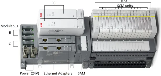
The purpose of the Select I/O subsystem is to provide a redundant and fault-tolerant system to provide input and output to the AC 800M processing modules, which are the central control units of the 800xA system. In the processing modules, all of the logic controlling the rest of the system resides, so it would be accurate to call this the brain of the system. And if the processing modules are the brain of the system, then the Select I/O could be thought of as the backbone that provides all sensory input and output to the PMs. The Select I/O subsystem itself consists of several minor systems, as described in figure8.
Figure 8: The different parts of the Select I/O subsystem. Not shown here is the Modulebus A link for the local GIO components and the SCM link that connects the SCM components.
Naturally, how these components interconnect is quite important. For a basic overview of the Select I/O internal network topology, see figure9. Below follows a short but more in-depth description of how everything is connected.
From the processor modules (PM), packets travel over a PROFINET link through the ethernet adapters (EA) to the field communication interfaces (FCI). Here, packets are converted to travel over a Modulebus medium. On the Modulebus, packets are ensured unique addressing by a safety addressing module (SAM) component known as HI880, before travelling onward to the generic I/O (GIO) component. At the GIO component, packets are converted again to the SCM link, where the actual signal conditioning modules (SCM) sit. Each layer is interconnected by redundant links, and the FCIs even have a direct redundancy signalling link between each other.
The reason for this convoluted network topology is to ensure a system availability of at least 99.999 per cent. All components of the Select I/O system use the standby modular redundancy method to ensure availability. While each individual component within the Select I/O system is not particularly complex, the network topology makes the system in and of itself very complex to model in a simulator, making it a very good candidate for a pilot project of this magnitude.
Figure 9: A schematic overview of the Select I/O subsystem network topology. From the left to right, the nodes shown are the Processing Modules (PM), Ethernet Adapters (EA), Field Com-munication Interfaces (FCIs), Safety Address Module (SAM), Generic I/O (GIO) and finally the actual I/O units called Signal Conditioning Modules (SCM).
5.2
Simulation
In order to save time, a component analysis was performed and only a single component was ultimately decided to be simulated. By choosing and focusing on a single component to model, it is much easier to create a simulation that may answer the questions asked.
5.2.1 Component analysis
Choosing a single component in this system requires some careful thought. Down below follows a brief suitability analysis of each component. The component should be able to be simulated but still be complex enough to offer some interesting results.
The processing module is the first stop. Because this module controls the entire unit and more or less acts as a stand-alone system-on-chip component, it is very easy to simulate. However, the output of this module comes from an Ethernet port, so the results of the simulation would not be very interesting since it has already been done quite a few times. It is better to simply connect a real PM to the computer directly in that case, or even use the soft controller product that runs in a Windows environment.
The Ethernet Adapter component is also not very interesting to simulate, since it is nothing more than a three-port Ethernet switch, with some extra logic. These components have already been simulated several times, and simulating them again would again not yield any interesting results.
Next component to write off is the HI880 module. This module is very simple in construction and has a single specific purpose of providing globally unique addresses to the GIO devices con-nected to the Modulebus. It should be more considered as a hardware extension to the Modulebus than an actual software component. Simulating this behaviour would be better to do as part of the Modulebus component than as a stand-alone module.
At the other end of the system, the SCM units are certainly worth a bit of consideration. However, the signals from these components can easily be simulated in whatever combinations that are desired, and therefore these modules are not a very interesting fit either.
The GIO component has the same problem as the SCM component, wherein any output it produces can be easily simulated or recorded and repeated to other components. So for the very same reasons as the SCM components, this component is not a good fit.
Last, but certainly not least, there is the FCI unit. The purpose of the FCI unit is to act as a bridge between the PROFINET and Modulebus links, as well as signalling the processing module(s) about the status. Furthermore, it also has a direct link to its redundant counterpart, through something called the Redundancy Link. This makes the FCI module the prime candidate for simulation when looking at the real system.
5.2.2 Simulation setup
Since only the FCI needs to be simulated in order to simulate and test the redundancy aspects of the system, the network setup as shown in figure10will be used.
Figure 10: The simulation topology. By simplifying and only focusing on simulating the FCI, a lot of complexity may be removed.
Simics already allows for virtualised embedded boards and frame-level simulation of the Eth-ernet stack but does not support the Modulebus component. In Simics, this bus would be a very simple device, where all messages going in on one port is echoed out on all other ports. The Modulebus component will be configured to always assume it works.
The I/O modules will be a simple mockup for the GIO components, implemented within the simulator in software. By adding these mockups, GIO responses may be sent back and forth over the Modulebus.
Finally, there will be a single processing module connected to the system itself. This might be mocked, but given that soft PMs already exists, it is better to simply connect one directly.
5.3
Connecting Hardware
While the simulation setup is important, it is also important to consider how the actual hardware for the Select I/O could be connected. By connecting real hardware to the simulation in this manner, quite a few additional concerns of interest may be raised. Among others, it would be possible to test inter-version compatibility and redundancy by letting the simulated hardware run v1.1 of the software and the real hardware run v1.0. Another benefit would be to connect any step of the chain towards the simulator in order to find bugs and run automated test cases.
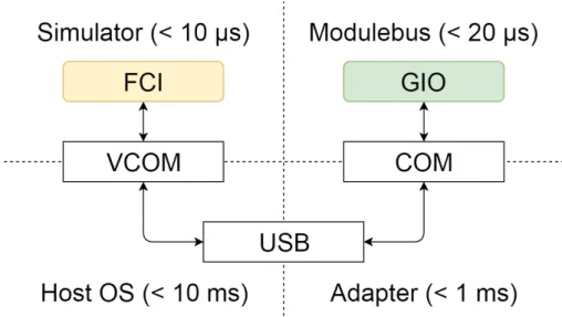
This task proves to not be as easy as pure simulation. While the PROFINET runs on Ethernet and Simics has no problem connecting a real hardware to the Ethernet bridge, the Modulebus and Scmbus links are not as easy. These two buses have very fast response times, with the Modulebus responding to the messages sent within a time span of 100µs and the Scmbus responding in around 300µs. Compare this with Ethernet that may have response times in the 50 ms range. The reason this is a problem is that the host operating systems that the Simics simulator runs on top of are usually very slow and non-responsive in comparison. See figure11for further information.
Figure 11: An overview of how much round-trip latency the entire simulation system would intro-duce. In the top left, the simulator will have a very small latency, typically in the nanoseconds range. It communicates through a virtual serial interface to the host OS, and from there to the actual bus itself. For modern computers, a USB adapter is often used as well.
The Windows operating system, for instance, typically has a delay of at least 3.5 ms from that a signal is sent until it is received by the application, and about the same trip back for the response. In between, the signal has to be analysed by a program (in this case Simics) and acted upon. Even with a response being generated in 1 ms or less, this means the minimum delay would be around 8 ms. Simply not good enough for the application at hand.
There are techniques that might be available to speed up the latency, but this in and of itself would be a thesis work and would require specific hardware, as well as specific hooks to the actual simulator itself. It would also be possible to slow down the hardware speeds to make this setup feasible, but given the complex nature of the system and the number of subsystems available, this solution requires a lot of work to implement. Therefore, for the Proof of Concept, the only part actually available to connect to the simulated FCI would be the processing module, and the other end would have to be implemented via the simulator for now.
5.4
Simulated components
In order to get a full Select I/O up and running, two specific components would need to be developed, namely, the two proprietary hardware buses that exist, Modulebus and SCM Link. For the proof-of-concept, only the Modulebus part was deemed necessary to create. The Modulebus utilise standard DE-9 connectors shown in figure12. It is a connector used for many different types of equipment requiring Serial communication.
In the real Select I/O, the Modulebus consist of two links, A and B. Each link is connected to both FCI and one of the GIOs. Both of them are controlled by the active FCI and the FCI
gets the data from the SCMs by polling the GIOs for data and asking for updates. The GIOs will then respond with relevant data. Meanwhile, the passive FCI will listen to everything that happens on the Modulebus and be ready to take over if necessary, but it will not interfere with the communication directly. Therefore, all communication happening on the link will occur between two parties at all times.
The Simics counterpart for the proof-of-concept became a simple serial connector hub, which in turn was modified from the serial link module within Simics. The functionality of this module is quite simple. Each byte being received on one connector will simply be echoed out on every other connector. This component is very limited and will not work with the real Modulebus since it has no way of addressing package frames at the moment. However, since only three components will ever be connected at the same time, and one of them will always be in a passive state and the other will only respond, in this case, the component was deemed sufficient for creating a proof-of-concept.
5.5
Software
The software run in the simulation is a specific build of the FCI firmware, based on the QSP-ARM architecture. The FCI runs the VxWorks embedded operating system, so in order to run this build a new kernel was built and implemented based upon the QSP ARM Base System Package (BSP). There were a number of issues with this approach that needed specific workarounds.
5.5.1 The Kernel
The kernel of the simulated FCI module was configured to be as close to the original firmware as possible. A couple of the kernel components were unfortunately not possible to implement in the QSP-ARM build, but these all had to do with peripheral functions such as firewall and SSH communication not deemed necessary to get a proof-of-concept up and running.
5.5.2 The FCI firmware
With the newly configured kernel, the FCI firmware was ready to be ported onto the simulated Simics machine. In order to load this hardware, a TAP connection was created and then the FCI was booted by using the Wind River Workbench Target Server functionality. By doing this, around 50 symbols in the lower layers turned out to be missing. Most of these symbols dealt directly with hardware and hardware sensory readings.
Unfortunately, not all symbols were suited for stubs, since a few required real hardware in order to run properly. These symbols could be divided into three distinct groups.
• Quite a few symbols interfaced directly with the Ethernet Adapter module. The Ethernet Adapter on the real hardware is treated as a 3-port switch, but it also has a couple of signal processing functions directly tied to the FCI and the FPGA board on the FCI platform. More work is therefore required to get these parts up and running on the simulated hardware. • One function created the file system RAM disk that the FCI use to store short-term logs.
Since no such file system existed on the simulated system, it took some time to debug and find the root cause of this problem. After a while, a solution emerged for this particular problem, but by then the code was already complete.
• Two more functions were missing drivers that fetched data, one for the temperature sensor and one for the network interface card. While these two functions were easy to stub out, their parents expected real data to be sent and did not like the NULL pointers sent. Apart from this, a few missing drivers were also a big issue. Dummy drivers would need to be developed and inserted into the hardware in order to resolve these issues completely. Once these issues are solved, the FCI should theoretically be able to run on the simulated hardware, but there are still a couple of issues left.
There are three interfaces to be concerned of on the FCI, the PROFINET interface which talks with the processing modules via the Ethernet adapters, the redundancy link between the two FCIs that does some internal signalling between the two units, and the Modulebus interface.
5.5.3 Redundancy link
The redundancy link is a simple serial link that sends signalling state and internal data necessary to keep an FCI in hot standby mode. It is a simple UART serial link and everything it needs to be up and running is already provided by the VxWorks operating system. Therefore this link works as-is on the simulated hardware.
5.5.4 PROFINET
At the time of writing, the PROFINET interface will not run properly within the simulation, with all of its tasks suspended. A quick investigation of why this happens has yielded no definitive answers. It could be that the Ethernet Adapter drivers found in the FCI firmware must be more fleshed out and that in turn will solve the problems. Another requirement might be that the FCI file system disks must be up and operational. This could be a simple fix or a very complex one, and further investigations are necessary before this becomes apparent.
5.5.5 Modulebus
The Modulebus interface is even more difficult than the PROFINET interface to get right. The Modulebus has, as discussed before, very high timing demands. These demands are difficult to meet in software alone, which is why the FCI utilise an FPGA to communicate with the Modulebus. The FPGA also does a few other tasks such as talking to the Ethernet Adapters, but the main purpose for the FPGA is the Modulebus communication. As a result, any simulated FCI must re-implement the FPGA communication done, either in pure software or with a real FPGA connected to the host.
There are several ways to replace the FPGA within the simulator, but due to lack of time, a decision was made to replace the FPGA routines with a software task running on VxWorks, as can be seen in figure13. The FPGA task thread ran at a very high scheduling priority, but would only execute while information was allowed to send. While this altered timing behaviours, it was deemed more important to get the Modulebus communication working. In this manner, the Modulebus communication actually worked as intended.
Figure 13: How the FCI FPGA communication works with the Modulebus. By replacing the FPGA with a high-priority thread running on the CPU, a slower but still acceptable implementation could be achieved.
6
Experimental results
Since so much time was spent on researching different frameworks and then, when Simics was decided upon, understanding the tools of Simics and VxWorks development, there was not much time to do experiments. Regardless, a few test cases were written with the research questions in mind. Once written, the tests were executed and the results recorded. Below is a description of the process of each of these tests, from the reasoning behind the tests to their implementation and results.
6.1
Use cases
Looking at the research questions, which ones can actually be properly tested for?
Research question 1 (Mixed Redundancy Testing) cannot be answered with the resources avail-able. It is possible to craft theories about it, but it would be very hard to verify those theories without building the three separate environments and create tests that work on all three. This would be an expensive endeavour for something that can mostly already be answered in theory.
Research question 2 (Suitability) is easier to answer. By creating a test that looks at the host system latency between hardware and Simics, it is easy to conclude the suitability of the mixed system approach. This was tested in 6.2. Also, by writing a simple test script that tests redundancy, it is easy to test the suitability and automation level that can be achieved with the Simics technology in software, and thus, to what level the technology can be used to create fully automated tests. This was tested in6.3.
Research question 3 (Integration) is also not solvable with a test. Instead, the question asked is whether or not the system lends itself to comparably easy integration. Again, this is very hard to test for in a concrete manner, and it is again a question more left to theorising.
Research question 4 (Scalability) can be tested. Since Simics allows for multi-machine testing, thousands, even tens of thousands of concurrent nodes can be tested. However, a multi-machine testing would introduce a lot more latency than what is required for the system. The system we are investigating have potentially hundreds of nodes, and therefore it is important to run a single model of the full Select I/O component and ensure that the simulator is, at the very least, capable of simulating that many nodes on a single host. The test for scalability was done in section6.4.
6.2
Test 1: Latency
With any simulation and hardware communication, latency will be present. It is important to measure the latency within the host system from the simulator to the actual hardware signals.
Since the host system used is a laptop running Windows 7, the only useful connector is the USB port. A more traditional desktop machine would be able to accommodate more direct com-munication through a PCI bus, but this is equipment is unfortunately not readily available at the moment.
Since a modern laptop only allows custom hardware to be connected to the USB port, it is possible to measure the latency from the USB port to the Windows handling of said port and get an accurate reading of this port. To measure this latency of the operating system, a tool called LatencyMon4 was installed and run, see figure14. LatencyMon is a tool that measures the delay
within the Windows operating system.
After the tool was installed, it was run ten times for ten minutes each time. The results of these runs are presented later on. After these runs, the latency of the host system to the USB port could be accurately measured.
Of course, this is not the only source of latency. There is also latency to convert the signals to the USB protocol as well as interpreting these packets in Simics. These latencies could not be properly tested since the tool to transfer electrical signals does not exist, and building a solution for that would take too much time. The test results also show that building such a tool would be of little value until the host OS latencies are resolved, which is why such an interface is outside the scope of this thesis.
Figure 14: The LatencyMon tool for testing latency within Windows.
6.3
Test 2: Redundancy
A quick and simple redundancy test suite was written and implemented. These tests can be found in appendixA. Most tests are about bringing down and starting up systems in a special order within Simics.
When writing these kinds of tests, there are two different kinds of testing to be made. One is black box testing, where signals are sent and output recorded and received, but whatever is inside the system is unknown. The other type of testing is white box testing, where the state and layout within a system are tracked as signals are sent.
While Simics has support for both white box and black box testing, it is easier to write an automatic test battery using black box testing, since fewer parameters need to be accounted for. A white box test also has to take into consideration that the internal state may change while the external state may not, and therefore keep the same functionality as black box tests. ABB also has a huge test battery of functional tests that are done almost entirely as black box tests. Since these could be borrowed to create a specially tailored test battery for this particular test, and time is short, the black box testing is what will be used. More detailed test batteries that monitor internal states of the various components could be implemented but is outside the scope of this thesis.
Regardless of which method is chosen, if one is to automate the testing, the expected result must be known before even running the test, in order to measure whether or not the test was a failure. If it is known that the test sends input A and expects result B, then the test will fail if the result is anything but B.
Since the FCI could only be brought into the simulation in a very limited capacity, a very simple component was instead implemented on top of VxWorks that contained the bare minimums necessary for a redundancy test. The logic of this component can be seen in figure15, and the two systems communicated over a serial link within the Simics environment.
Figure 15: Overview of a simple redundant standby system. The system starts in the lower left by setting a watchdog timer (t) and listens as a passive component. If the watchdog runs out, it will move to active mode, where it remains until the system is shut down. All I/O is non-blocking.
6.4
Test 3: Scalability
In order to test the performance, a third test was constructed. In this test, a full-scale select I/O with 192 SCMs, 2 FCI units and 24 GIO computers were implemented, along with Ethernet links between everything. The way they are connected can be found in figure16and the specification of each part can be found in table1.
System OS Platform Quantity Frequency Cores Network Serial
EA - Eth. Switch 2 - - 3
-Modulebus - Eth. Hub 2 - - 14
-SCM Link - Eth. Hub 12 - - 18
-FCI vxWorks QSP-ARM 2 400 MHz 2 2 2
GIO vxWorks QSP-ARM 24 80 MHz 1 2 1
SCM vxWorks QSP-ARM 192 24 MHz 1 1 1
Table 1: An overview of the different components for the full-scale test. The columns list their underlying OS, the underlying platform, (maximum) number of components included, their CPU frequency, and the number of CPU cores, network ports and serial ports.
The Modulebus use two channels, A and B, and for every Modulebus channel up to 12 GIO modules may be connected. Behind each GIO module sits up to 16 SCMs. GIOs are included in pairs due to redundancy requirements, which means that for every 16 SCM added, another GIO pair is added, and each GIO communicate with a single bus.
By running a full-scale test, it is possible to evaluate whether the method to run a mixed environment on a single host is feasible with modern hardware. It is also interesting to add SCM units incrementally, to see not only if the full 192 SCM network is possible, but if it is not, where the boundary lies.
A final interesting thing to observe is how simulation performs under load. This is achieved by putting busy wait loops with lower and lower sleep periods to simulate loads.
The test methodology being utilised is very simple. The setup shown is loaded into Simics and then run for 10 minutes. After that, the time in the simulator is measured and the ratio between the simulator time and the actual time is compared. Each time the number of SCM units is increased by 16.
Figure 16: An overview of the full-scale redundant test system. Note that the GIO/SCM structure is simply repeated for a total of 12 groups. The FCI and GIO come in redundant pairs, but for this particular test is only there to offer a better sense of scalability.
6.5
Results
Below follows the results from the tests described above. 6.5.1 Latency results
For the results of the latency test, see table2.
Test Max ITP Max ISR Max DPC Pagefault Resolution
1 3055.34µs 437.031 µs 3303.83 µs 224 645µs 2 2724.96µs 337.435 µs 2773.34 µs 637 886µs 3 5699.13µs 419.729 µs 3270.34 µs 49 943µs 4 3025.51µs 415.109 µs 3088.27 µs 49 832µs 5 13 270.3µs 350.791 µs 2886.02 µs 49 862µs 6 14 936.2µs 389.861 µs 3404.07 µs 77 348µs 7 33 553.3µs 403.845 µs 33 506.0 µs 999 887µs 8 11 824.9µs 343.337 µs 7343.09 µs 74 466µs 9 2722.32µs 121.138 µs 1223.58 µs 5376.16µs 10 2091.77µs 377.350 µs 968.664 µs 5619.22µs Average 9290.37µs 359.563 µs 6176.72 µs 217 486µs
Table 2: The results of the latency test. From left to right, the latency of Interrupt to Process (ITP), Interrupt Service Routine execution time (ISR), Deferred Procedure Call latency (DPC) and finally, the time to resolve pagefaults.
6.5.2 Redundancy results
The redundancy test battery was run and proved that indeed automatic redundancy testing is possible with Simics. See appendixAfor further information on what tests were run.
6.5.3 Scalability results
For the results of the scalability test, see table3, figure17and figure18.
FCI Units GIO Units SCM Units Idle Light Half Heavy Full
2 2 1 27.6 1.37 0.81 0.53 0.39 2 2 16 23.4 1.17 0.66 0.46 0.33 2 4 32 19.9 0.93 0.55 0.41 0.3 2 6 48 16.5 0.8 0.45 0.34 0.26 2 8 64 13.6 0.66 0.4 0.28 0.22 2 10 80 11.2 0.57 0.33 0.23 0.18 2 12 96 9.5 0.48 0.28 0.2 0.16 2 14 112 7.9 0.42 0.25 0.18 0.14 2 16 128 7.1 0.38 0.21 0.15 0.12 2 18 144 6.1 0.33 0.19 0.14 0.1 2 20 160 5.5 0.3 0.17 0.12 0.1 2 22 176 4.87 0.27 0.15 0.11 0.09 2 24 192 4.3 0.24 0.14 0.10 0.08
Table 3: The results of the scalability test. The load numbers are 0, 25, 50, 75 and 100 percent load, respectively, and the numbers are the ratio between the simulated time and real time.