M
ÄLARDALENU
NIVERSITYS
CHOOL OFI
NNOVATION,
D
ESIGN ANDE
NGINEERINGV
ÄSTERÅS,
S
WEDENThesis for the Degree of Master of Science (60 credits) in Computer
Science with Specialization in Software Engineering 15.0 credits -
DVA423
C
ONSISTENT INTEGRATION OF SYSTEM AND SOFTWARE
MODELS AT DIFFERENT LEVELS OF ABSTRACTION
Emina Smajlovic & Amina Krekic
esc17001@student.mdh.se ; akc17003@student.mdh.se
Examiner: Antonio Cicchetti
Mälardalen University, Västerås, Sweden
Supervisor: Jan Carlson
Mälardalen University, Västerås, Sweden
Company Supervisor: Jagadish Suryadevara
Volvo Construction Equipment AB, Eskilstuna, Sweden
different levels of abstraction
2
Abstract
Due to numerous domain needs, aspects and requirements, various preferences and diversity of organizations, development of complex embedded systems mostly requires using many different tools and modeling languages. Since corresponding data is repeated in multiple models, at different levels of abstraction and expressed in different modeling languages, it is very challenging to keep these models consistent and up to date as the system evolves. A case study from one of Volvo CE’s vehicles has been used to identify and investigate the relation between models in an actual case. With the aim of improving the development process of embedded systems, the gap between models describing different aspects of the system has been addressed. An existing example of one system function has been analyzed and discussed. SysML models and Simulink models of the function were examined in order to identify dependencies between them. After the dependencies were found, they have been generalized into a list of various dependency types. During the case study, it has been noticed that these models are not one-to-one related which makes the automatic conversion between them harder, and a number of gaps between SysML and Simulink models were identified. Further, possible ways of improvements are proposed in order to achieve a consistent integration of system and software models at different levels of abstraction.
3
Table of Contents
Abbreviations 5
Figures and tables 6
1. Introduction 7
2. Background 9
2.1. SysML 9
2.1.1 Block Definition Diagram 11
2.1.2 Internal Block Diagram 12
2.1.3 State Machine Diagram 12
2.2 Simulink 13 2.2.1 Block 13 2.2.2 Signal/Line 14 2.2.3 Input/Output Port 14 2.3 EAST-ADL 14 2.4 SE-Tool 16 3. Related Work 18 4. Problem Formulation 20 5. Method 21
5.1. Ethical and Societal Considerations 23
6. Modeling at Volvo CE 24
6.1. “Brake” function description 24
6.2. Analyzed “Brake” function models 28
7. Identified dependency types 29
7.1 Block ←→ Block 30
7.2 Flow Port ←→ Input/Output Port 31
7.3 Connector ←→ Line/Branch Line 33
7.4 Block Composition ←→ Block Subsystems 34
7.5 State Machine ←→ If-Else Blocks 35
7.6 Constraint block ←→ Dynamic equation 37
7.7 Flow properties ←→ Bus object 37
8. Discussion 38
9. Threats to Validity 40
10. Conclusions and Future work 42
11. References 43
different levels of abstraction
4
Acknowledgements
We are using this opportunity to express our gratitude to everyone who supported us throughout this study. We are sincerely thankful to our supervisor, Jan Carlson, for his support, guidance and friendly advice during this case study. He was always steering us in the right direction and giving us valuable comments. We would also like to thank Volvo CE employers who provided us facilities and conducive conditions which were required.
5
Abbreviations
AC - Alternating CurrentADL - Architecture Description Language AF - Analysis Function
AUTOSAR - AUTomotive Open System ARchitecture BDD - Block Definition Diagram
CAF - Complete Analysis Function DC - Direct Current
E2E - End-to-end
E&E - Electrical and Electronic FD - Functional Device
IBD - Internal Block Diagram IF- Interface
MBD - Model Based Development OMG - Object Management Group SysML - Systems Modeling Language UML - Unified Modeling Language VCE - Volvo Construction Equipment
different levels of abstraction
6
Figures and tables
Table 1 - List of dependency types between SysML and Simulink models Figure 1 - SysML diagram types
Figure 2 - The four pillars of SysML Figure 3 - Example of BDD
Figure 4 - Example of IBD
Figure 5 - Example of State Machine Diagram
Figure 6 - A simple example of input port, output port, block and signal/lines in Simulink Figure 7 - Abstractions layers in EAST-ADL
Figure 8 - Electronic System Architecture levels Figure 9 - The activity tree of “Brake” function Figure 10 - Sequence diagram of “Brake” function Figure 11a - Drivetrain block in SysML
Figure 11b - Drivetrain block in Simulink
Figure 12a - Brake machine Input/Output ports in Simulink Figure 12b - Brake machine flow port in SysML
Figure 13a - Powertrain to Drivetrain Line in Simulink
Figure 13b - Powertrain to Drivetrain and Wheels Connector in SysML Figure 14a - Block composition in SysML
Figure 14b - Block Subsystems in Simulink Figure 15a - If-Else blocks in Simulink
7
1. Introduction
Embedded Systems play a truly important role in almost every type of product nowadays. This research area has been increasingly growing and designing high-quality embedded systems in a shorter period of time has become a big challenge for engineers.
Different market needs and demands, such as developing systems with higher complexity within reduced development time, have led to the acceptance of Model Based Development (MBD). MBD is established on the end-to-end use of precise software models which can be manipulated and controlled. It allows engineers to ensure higher flexibility and reduce costs that software control requires. Therefore, MBD has become a dominant software development paradigm in vehicle domains. MBD changed the idea and the approach engineers used to apply and it is considered as one of the most effective tools used while developing complex embedded systems. Since the significance of embedded systems is undeniably seen in the Automotive Industry, there is a strong interest for developing robust MBD tools which would be used to design automotive embedded systems with increased safety and decreased development time.
During modeling complex embedded systems, many factors need to be taken into accounts, such as system requirements, functionality, architecture and that is the reason for including many different tools and modeling languages. The Systems Modelling Language (SysML) models describe system architecture and functionalities at a higher level of abstraction. EAST-ADL gives an extension of SysML dedicated to automotive embedded systems [13]. On the other hand, Simulink models are used to describe behavioral aspects of a software system at a lower level of abstraction.
The contribution of this thesis project is a relationship investigation between different concepts of the structural and behavioral system aspects and their models. Concrete function and its SysML and Simulink models will be discussed in this paper. This report will also describe demands and circumstances regarding usage of two different languages, Simulink and SysML. The study is motivated by the fact that Simulink is widely used and accepted tool for designing and simulating dynamic systems, while on the other hand, SysML is commonly used as a basis for the design of the architecture and functionalities of embedded systems. Combined usage of Simulink and SysML provides significant support for specification, analysis, design, verification and validation and highlights benefits of both languages. The goal of this thesis project is to conduct an analysis of the combined usage of Simulink and SysML in a specific function, in order to find links between Simulink and SysML models. To achieve the goal, the following steps will be conducted:
● Investigate in which way functionalities are developed and represented in Simulink and SysML.
● Discover connections between models at different granularity and different levels of abstraction (in particular, between system models in SysML and detailed design models for individual functions or subsystems in Simulink).
different levels of abstraction
8
● Formalize identified links between Simulink and SysML models of the function. In section 2 we provide the theoretical background on the concept of software modeling languages and tools (SysML, Simulink, EAST-ADL, SE-Tool). Related work is presented in section 3. In section 4 the problem formulation is given together with research question. Steps which have been followed in order to answer the research question are described in section 5. Section 6 gives an overview of “Brake” function. Identified dependency types can be found in section 7. Discussion is given in section 8. Conclusion and future work can be found in section 9.
9
2. Background
To manage the development of complex industrial embedded systems, it is important to effectively handle system life cycle phases, mainly system requirements, design and software development. Often these phases involve cross-functional / cross-domain aspects.
Development of embedded systems is mostly followed by handling various tools and languages, considering numerous domain demands, aspects and requirements, diversity of organizations, and different preferences, needs, rights and legacies. Taking into account the fact that it is not conceivable to determine a single language for all purposes, we come to the conclusion that a need for connecting several tools and modeling languages cannot be disregarded.
In this case study, different modeling languages are used to model different parts of a software system. For storing, managing and retrieving all information that is needed to specify an Electrical and Electronics (E&E) system, Volvo CE is using SE-Tool. For representing behavior and structure views, Volvo CE is using Matlab Simulink and SysML. The Systems Engineering Framework at VCE referred to as SE-Tool, is a customization of the commercial tool Systemweaver according to software development processes at VCE. SE-Tool is an implementation of the EAST-ADL language, to support complete software development processes at VCE. It is primarily used to develop the complete E&E System in software as well as hardware. All the requirements and function descriptions are defined in SE-Tool. Further, final SysML models of functions defined in SE-Tool are created in IBM Rational Rhapsody tool.
Consideration of the prosperity and richness of the aforementioned languages brings up the conclusion that their combination in development of complex industrial embedded systems can provide great significance since they are designed for different purposes.
Following subsections give an overview of SysML, Simulink, EAST-ADL and SE-Tool, respectively.
2.1. SysML
The Systems Modeling Language (SysML) is a general-purpose modeling language, based on the actual standard for software engineering, the Unified Modeling Language (UML) developed in the Object Management Group (OMG) consortium [1].
SysML is mainly used for system architecture representation, along with behavioral and structural aspects of the system. It has been developed as an upgrade of UML, considering all the experience gained by using UML for designing and representing software architecture. While designing system models, functional and structural aspects are taken into account, depending on needs. Figure 1 identifies the SysML diagram types.
different levels of abstraction
10
Figure 1 - SysML diagram types [14]
SysML diagrams can be used to specify system behavior, requirements, structure and parametric relationships. The system structure can be represented with a block, internal block and package diagrams. The system hierarchy and system classifications can be described with block diagram. The internal structure of a system (its parts, connectors and ports) can be described with Internal Block Diagram. The organization of a model is described with package diagram.
The system behavior can be represented by activity, sequence, state machine and use case diagrams. The flow of data between activities is described with activity diagram. The interaction between parts of a system that collaborate is described with a sequence diagram. The state transitions and actions of the system or its parts in response to events is described with State Machine Diagram. A high-level description of the functionality of a system is provided by use case diagram. The relationships between requirements hierarchies and the derivation, satisfaction, verification and refinement are captured by requirement diagram. Constraints on system parameter values (performance, reliability etc.) are represented by a parametric diagram. Figure 2 represents the four different pillars of SysML where we can see a simple example of aforementioned key diagram types of SysML. Stated figure presents the anti-lock braking system. Structure is described by Block Definition Diagram, where the components are represented by different blocks. Central block is an Anti-lock controller, which is composed of two parts: traction detector and brake modulator. The ways to present the behavior of a system is by interaction, state machine and activity diagrams. Requirements diagrams are made before we actually know what pieces of structure we are dealing with and they are very useful in refinement of functional requirements. In Figure 2, it can be seen that requirements diagram contains Vehicle system specification and Braking subsystem specification, which are connected through their requirements. Parametric diagrams are used in order to make the parts of a diagrams more reusable. In the Figure 2, we can see a parametric diagram of a block Straight line vehicle dynamics, which includes four separate equations.
11
Figure 2 - The Four Pillars of SysML [11]
In this paper, we will rather focus on structure and behavior diagrams. In particular, Block Diagrams and State Machine Diagrams will be explained in more detail below.
2.1.1 Block Definition Diagram
Block Definition Diagram (BDD) in SysML defines features of blocks and relationships between them. Blocks are modular units of system description. A collection of features to describe a system is defined by each block. An example of a Block Definition Diagram is given in Figure 3. In the given example we can see the ABS Structure Hierarchy, where its different parts are represented with blocks that are connected with ports. The composition is shown by black-diamond connection between Anti-Lock Controller, Traction Detector and Brake Modulator.
different levels of abstraction
12
Interaction points on blocks and parts are specified by SysML ports. They integrate behavior with structure. There are two different kinds of ports:
- Standard (UML) port - specifies a set of operations and signals, typed by a UML interface
- Flow port - specifies what can flow in/out of the block 2.1.2 Internal Block Diagram
Internal Block Diagram (IBD) is formed on UML composite structure diagram but adjusted and extended as defined by SysML. IBD is mainly used to describe the internal structure of the blocks, showing its parts and connections between them. Also, all blocks may describe behavior. Block whose name is found in the heading of the diagram is the owner of properties and connectors inside the IBD. The figure below shows an example of IBD which represents an internal structure of Anti-Lock Controller. The communication between its internal blocks Traction Detector and Brake Modulator is defined by the c2 interface. The interaction points of blocks are flow ports with out and in direction of data flow, respectively.
Figure 4 - Example of IBD [10]
While BDD specifies a block as a black-box representation, IBD defines white-box part implementation. Thus, BDD and IBD diagrams complement each other.
2.1.3 State Machine Diagram
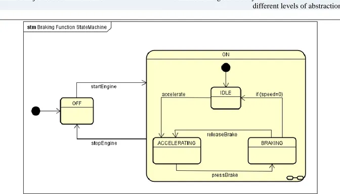
State Machine Diagram is used to represent the life cycle of a block. The invoked activities during the transition, entry, and exit of the states are specified together with the associated event and guard conditions. There are three types of events: change event, time event and signal event. Activities that are invoked can be continuous or discrete. Figure 5 shows the example of a State Machine Diagram which represents the Braking function. Based on the engine state, the machine can be in two main states: ON and OFF. When the engine is started and the machine is not moving, the machine is in IDLE state. If the machine accelerates, the machine state is changed to ACCELERATING. If the brake is pressed, the machine state is changed to BRAKING. If the brake is released and the machine is still moving, the state is changed to ACCELERATING, otherwise, the state is changed to IDLE.
13
Figure 5 - Example of State Machine Diagram
2.2 Simulink
Simulink is a block diagram environment for multi-domain simulation and Model-Based Design and utilize of Simulink enables simulation, automatic code generation, and continuous test and verification of embedded systems [2].
Established by The MathWorks, as a commercial tool for structuring, designing, simulating and evaluating dynamic systems, Simulink provides compact integration with MATLAB environment. The initial interface of Simulink contains a graphical block diagramming tool and adjustable set of block libraries used as a solver for modeling. Compared with text-based programming languages, Simulink provides a simple way of developing a model, since it includes integrated model solvers.
Generally, Simulink is used in control theory and digital signal processing for designing and simulation of dynamic systems.
2.2.1 Block
Blocks in Simulink can represent equations and modeling approach. They are the fundamental elements used for building models in Simulink. There are different types of blocks that can be found in Simulink block libraries: continuous function blocks, control and indicator blocks, discontinuous function blocks, logic or bit operation blocks, lookup table blocks, mathematical function blocks, blocks for self-verifying models, model-wide operation blocks, blocks related to subsystems, modify signal attribute blocks etc.
different levels of abstraction
14
2.2.2 Signal/Line
Signals in Simulink are the outputs of dynamic systems represented by blocks. Signals can have different attributes, including [2]:
● Signal name
● Data type (for example, 8-bit, 16-bit, or 32-bit integer) ● Numeric type (real or complex)
● Dimensionality (one-dimensional, two-dimensional, or multidimensional array) The lines in Simulink are used to represent those signals.
2.2.3 Input/Output Port
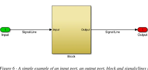
Input ports in Simulink are the links from outside a system into the system, while Output ports are the links from a system to a destination outside of the system. Figure 6 shows an example of an input port, an output port, block and signals/lines in Simulink.
Figure 6 - A simple example of an input port, an output port, block and signals/lines in Simulink
2.3 EAST-ADL
EAST-ADL is an Architecture Description Language (ADL) initially defined in the ITEA project EAST-EEA around 2000 [3].
EAST-ADL has later been refined by internationally financed projects to coordinate with the current Automotive Open System Architecture (AUTOSAR) standard. It provides a comprehensive approach for representıng automotive embedded systems through information models [3].
EAST-ADL is based on UML and SysML concepts but adjusted for automotive purposes. For example, the requirements concepts are aligned with the SysML, but they are adapted to
15
follow the structure of EAST-ADL. Compared with SysML, EAST-ADL is more low-level, so it can be considered as a subset of SysML for automotive embedded systems.
Features of EAST-ADL potentiate representation of many aspects, such as vehicle functions, composed requirements, analysis functions, hardware and software components and a connection between them. It is possible to detect, identify and trace elements using EAST-ADL’s low level of abstraction, but also using AUTOSAR’s implementation level.
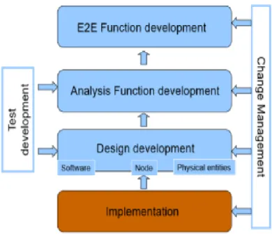
EAST-ADL language prescribes abstraction levels which express different views and details of the software architecture. Although abstraction levels indicate all the stages of an engineering process, it is on company how are they going to apply that process. EAST-ADL is structured in four abstraction layers and possible representations, as shown in figure 7. The significance of EAST-ADL reflects in creating a support for modeling vehicle components and its environment in order to complete validation and verification. All the modeling entities can be traced and all the requirements can be modeled.
Figure 7 - Abstraction layers in EAST-ADL [3]
A Vehicle Level creates a system description in the highest level and manages the features of the product in general, based on functionalities required by stakeholders. It describes what should system do, but not how it should be done. The vehicle level is commonly known as end-to-end level because it describes end-to-end vehicle functionalities. Each of functionalities is presented by Vehicle feature, while the relations between features are realized by feature links.
An Analysis level, presents vehicle functionalities, using formal notations to express behavior and interface. Analysis level is followed by design and implementation levels, so design and implementation details are excluded. It can be useful to conduct high level analysis since functional verification may be carried out.
different levels of abstraction
16
A Design Level architecture further describes and specifies the Analysis Level design since it concerns about the software and hardware resources. In other words, it defines a function to hardware allocation. Design Level actually captures the concrete functional definition and pays attention to the final implementation.
An Implementation Level presents the software-based implementation of the entire system. Software components perform all software functionalities and AUTOSAR software perform the platform. Accordingly, implementation level modeling relies on AUTOSAR model elements.
2.4 SE-Tool
For storing, managing and retrieving all information that is needed to specify an E&E system, Volvo CE is using SE-Tool. SE-Tool is an adaptation made by Volvo of the commercial tool SystemWaver. The adaptation includes all types used in the tool - like Analysis Functions or Requirements, as well as reports and custom tool views. SE-Tool is compatible with the main ideas of EAST-ADL concepts and is addressing all levels of Electronic System Architecture. Figure 8 shows different Electronic System Architecture levels.
Figure 8 - Electronic System Architecture levels [12]
The End-to-End functions (E2E) serve several purposes. The purpose of E2E functions is reflected in discussion between product planning and Electric-and-Electronic (EnE) development where E2E functions serve as a basis. Ideally, every E2E function needs to be independent and reusable, described as a black-box with focus on functionality itself without giving attention to the way how is it achieved. In Volvo CE, whenever an E2E function is identified, it must be documented in SE-Tool. The function description should include the overall machine level function and the conceptual solution for this function in terms of interacting subsystems where the EnE system is considered as one of the possibly several
17
subsystems. To get a better understanding of the function, the E2E description can be extended with use cases as an optional way of visualizing and describing functionality. In SE-Tool, the analysis level is a decomposition and formalization of the incoming End-to-End requirements into analysis function and analysis requirements good enough to use as input for design, implementation and test. From the End-to-End function, the functionality is decomposed into Analysis Functions (AF) describing the responsibilities and Functional Devices (FD) that formalize the interfaces to other subsystems including hardware. The collection of analysis functions and functional devices represent a Complete Analysis Function (CAF). In system design level, analysis functions are allocated onto hardware.
different levels of abstraction
18
3. Related Work
MBD implies inclusion of models in every phase of software development and these models are formed using different tools. Herrmannsdoerfer et al. [15] conduct an empirical investigation about the status quo of currently used tools for MBD and requirements for next generation of those tools. Results show that the most important demand that has to be considered in the future is deep integration and adaptability of tools and languages. Our case study shows importance of the combined usage of several tools and languages, like Simulink and SysML, in industry.
Simulink is widely used and accepted tool for designing and simulating dynamic systems, while on the other hand, EAST-ADL is commonly used as a basis for design of the architecture and functionalities of embedded systems. EAST-ADL is based on concepts from UML, SysML and AADL, but adapted for automotive needs. Several surveys and case studies exist that are discussing a combined usage of Simulink and UML. [4], [6] and [7] focus on research of structural and behavioral mappings between Simulink and UML. On the other hand, we focus on research of structural and behavioral mappings between Simulink and SysML with focus on elements of SysML that are not part of UML set of elements. There are several research studies that focus on combined usage of SysML and Simulink, but there are no research studies that focus specıfıcally on finding dependencies between SysML and Simulink.
Servat et al. [4] investigate the needs and some of the circumstances of combined usage of Simulink and UML. Research of structural and behavioral mappings is done with the focus on continuous-time and discrete-time models. They present a procedure for transforming Simulink models to UML combined structure and activity models. A mapping of the Simulink language to combined structure diagrams and attachment of behavior separately is suggested. The authors focus on closely related subsets of UML and Simulink and propose that Simulink models can be described by UML composite structure diagrams combined with activity diagrams for behavior. Similar to that, we propose that Simulink models can be described by SysML Structural Block Diagrams combined with State Machine Diagrams for behavior. Since the authors have used UML 2.0 profile, on which SysML is based, the list of the proposed structural mapping rules corresponds to the subset of the identified dependency types in this thesis report (i.e. block - block, block composition - subsystem block, line/branch line - connector, flow port - input/output port). Compared to [4], our work is more specific since it is based on the concrete example from the industrial settings and the dependencies are corroborated with the example.
Shi et al. [6] investigate the demands and some of the possibilities in the simultaneous usage of Matlab/Simulink and UML. Structural and behavioral mappings are explored considering the demands for models at different abstraction level as well as environment models. The representation and mapping between behavioral models, including discrete-time, event-triggered, and continuous time systems is of special concern and solutions are discussed. Similar to [4], the list of the proposed structural mapping rules corresponds to the mentioned
19
subset of the identified dependency types in this thesis report. When describing behavioral aspects of UML, the authors of [6] focus mostly on activity models. On the other side, we mostly pay attention to State Machine Diagrams representing behavioral aspects of the system.
UML is a semi-formal modeling language and the lack of accurate semantıcs makes it difficult to validate the correctness of embedded software development. To solve this problem, Guo et al. [7] present a model transformation method between UML design model and Simulink simulation model. The method consists of a UML State Machine meta-model, a Simulink/Stateflow meta-model and a set of mapping rules from the UML meta-model to the Simulink meta-model. They apply this method to a flight control software autopilot system. The method implements an automatic transformation from UML to Simulink, improving development efficiency of embedded software and providing technical support for embedded software development, such as automobile control system and avionics system.
Several research papers focus on simulation of SysML/EAST-ADL functions in Simulink ([5], [8], [9]). In order to make the simulation possible, mapping rules are set.
Marinescu et al. [5] present a constellation of analysis techniques for architectural models described in EAST-ADL. They propose three analysis techniques of EAST-ADL architectural models based on the demands of the current model based development to tackle some of the design needs that includes simulation of EAST-ADL functions in Simulink. This is the case study where the authors show the potential of simulating EAST-ADL models in Simulink. Even if SysML is considered a flexible and standard tool for system engineering, using only descriptive models are insufficient for system behavior verifications. To handle this matter, simulation environments like Matlab/Simulink are used to verify if the system preliminary design satisfies the requirements or not. Chabibi et al. [8] propose an integration approach based on metamodeling and model transformations to generate Simulink models from SysML diagrams. This approach is handled by models and modern techniques of Model based engineering. The authors have found the dependencies between State Machine Diagrams in SysML and Simulink, while we have focused on Block Definition diagrams.
Sjöstedt [9] has investigated several architectural description languages and tools, including EAST-ADL, SysML and Matlab/Simulink. He has conducted a case study to show the usage, the differences and the similarities of mentioned languages and tools. The result of this study is a method to describe how the simulation behavior of Matlab/Simulink model has been developed using SysML activity diagrams. Sjöstedt investigates how one model can be developed using another model which leads to some dependencies being created while we focus on identifying dependencies between models that are developed separately. In [9], the industrial case study is used to simulate the environment, in a similar way like it was done in this thesis report, where we had used Volvo CE models.
different levels of abstraction
20
4. Problem Formulation
The focus of this thesis is on different levels of abstractions of the system which are presented in SysML and Simulink models. SysML models show the static features of a system or subsystem, representing the framework for the system or subsystem, which contains all the components and their connections. Opposite of that, Simulink models specify the dynamic nature and interaction in the system or subsystem.
Developing complex industrial embedded systems includes managing all system life cycle phases. Almost always, different parts of functions are modeled using different modeling languages and tools, depending on whether they need to be represented with behavioral or structural models. The problem that arises is related to the correlation between different artifacts of the function, mostly because of the dependencies between them. Since the parts of functions are usually designed and developed separately, troubles during the integration of a function might occur. Considering different modeling artifacts representing a single function or part of a system, it can be perceived that structural and behavioral design models of individual functions or parts of the system in SysML may reflect on structural and behavioral design models of individual functions or subsystems in Simulink (and vice versa), because of their tight connection and dependencies between them. Consequently, while designing models for every single artifact, all the dependencies and connections with other parts of the function have to be considered. The potential problem that arises, in that case, is related to the way how should those dependencies be modeled.
One way to reduce the stated problems is to introduce more formalized system level modeling including representation interactions and dependencies between subsystems, but since some information is repeated in multiple models, at different levels of abstraction and expressed in different modeling language this can be very challenging.
In order to solve the aforementioned problems, we are going to answer following research question:
RQ1: What types of dependencies exist between system level models in SysML and detailed
21
5. Method
In order to go throughout the work and evaluate the derived approach, a case-study had been conducted. Since the research has been conducted in industrial settings at Volvo CE and actual work is done in a real environment in its natural context, the case study is a suitable method.
The case study allows taking an extensive and complex topic, which is then narrowed down into specific research questions. Therefore, considering the size and nature of this research study, the case study appears as a logic choice. Case study as a research method requires identification of major factors which might affect the results. Case study research is an observational study, i.e. it is done by observation of an on-going project [16].
It starts with deep analysis of the known facts about the research field, and then continues with collection of qualitative and quantitative data. Qualitative data relates to research objects in their natural environment and requires expert knowledge of a research field. On the other hand, quantitative data relies on statistical analysis based on measured values and it can be viewed as more objective and rational than qualitative.
In order to answer the stated research question, we have analyzed requirements documentation and understood the complex end-to-end function of one subsystem. Since the function is represented in both SysML and Simulink models, we have examined functional SysML models and Simulink models in order to identify dependencies between them. We have then generalized and categorized the dependencies. Then, based on the nature of the dependencies, we have investigated if there is the possibility to modify existing SysML and Simulink models, so consistent integration of stated models at different levels of abstraction could be realized.
The case study from one of the Volvo CE vehicles (i.e. wheel loader) has been used to conduct the research and evaluate the approach.
Our thesis work consists of the following steps:
1. Identify the main problem
Considering that the development of embedded systems requires the use of different tools and languages for different demands, aspects and requirements, preferences, needs, rights and legacies, it is inevitably to combine more tools/languages. Interactions and dependencies between subsystems are generally managed by experience, so the problem arises during integration in case that the interaction is unlike the expected.
2. Determine and define the research questions
In order to solve the stated problem in step 1, we have determined and defined the research questions. All further analysis in this case study is done so the answer to these research questions would be found.
different levels of abstraction
22
3. Literature review of current state-of-art of combined usage of SysML and Simulink
In existing literature authors talk about combined usage of SysML and Simulink, but no one focuses on a consistent integration of models at different levels of abstraction while using a set of different tools and languages for modeling. In section 3 the previous works are examined and correlated with our work.
4. Analyse requirements documentation of a complex end-to-end function
SysML-based modeling at Volvo CE is currently based on a reverse-engineering approach with capturing functionality from existing requirements in SE-Tool and Simulink models. The analysis of their modeling approach together with the nature of the organization is performed. The “Brake” function is chosen and serves as an example in order to do an analysis in the research. In section 6, the “Brake” function is further described and explained.
5. Analyse and discuss SysML and Simulink models of a complex end-to-end function
SysML and Simulink models are used for describing the “Brake” function. In section 6, the SysML and Simulink models of the examined function are discussed.
6. Find correspondences and observe dependencies between SysML and Simulink models
On the basis of the analyzed models and the related work, the correspondences between models are found and it is observed that they are not one-to-one related. However, dependencies between them exist and some examples of them are presented in section 7.
7. Classify the found dependencies into a list of dependency types
The list of dependency types is made as a result of this case study. Table 1 in section 7 represents the summary of dependency types.
8. Discuss what changes could have been made in SysML/Simulink models so the consistent integration would have been achieved
There are different ways that lead to consistent integration which include a modification of SysML and/or Simulink diagrams for the purpose of handling mentioned dependencies, and they are discussed in section 9.
9. Conclude the analysis by reviewing the work
To conclude the analysis the review of the work is done to make sure that the research questions are answered. The conclusion of this case study can be found in section 10.
23
5.1. Ethical and Societal Considerations
This study has involved some confidential data, such as existing requirements documentation, SysML and Simulink models of the considered end-to-end function, provided by Volvo CE. Although the validation, which is done in the industrial environment, is presented in a neutral manner, without revealing sensitive information, the solution itself does not involve confidential data and can be applied to other cases too. Thesis authors are responsible for all provided data and outcomes of the study have been presented to Volvo CE.
different levels of abstraction
24
6. Modeling at Volvo CE
At VCE, to describe a behavioral and structural abstraction level of the system, Simulink and SysML are used. The SysML-based modeling at VCE is based on reverse-engineering approach, i.e. capturing functionality from legacy concepts and corresponding implementations in the hardware and software (e.g. Simulink based environment). Since the SysML and Simulink models of the system are developed by different groups in the organization, there is no exact one-to-one relation between these models. To investigate the nature of dependencies between these models, the “Brake” function is described and examined.
6.1. “Brake” function description
A common wheel loader drivetrain system combines a clutch, a transmission, a drive shaft, and an axle connected between the engine and the driven wheels. The link between the clutch and the engine provides driving connection to the transmission, which further gives a majority of speed change gear ratios between the clutch and the drive shaft. In order to perform braking following components are involved: Operator, Requester, Engine, Wheel, Generator, DcLink and HubUnit.
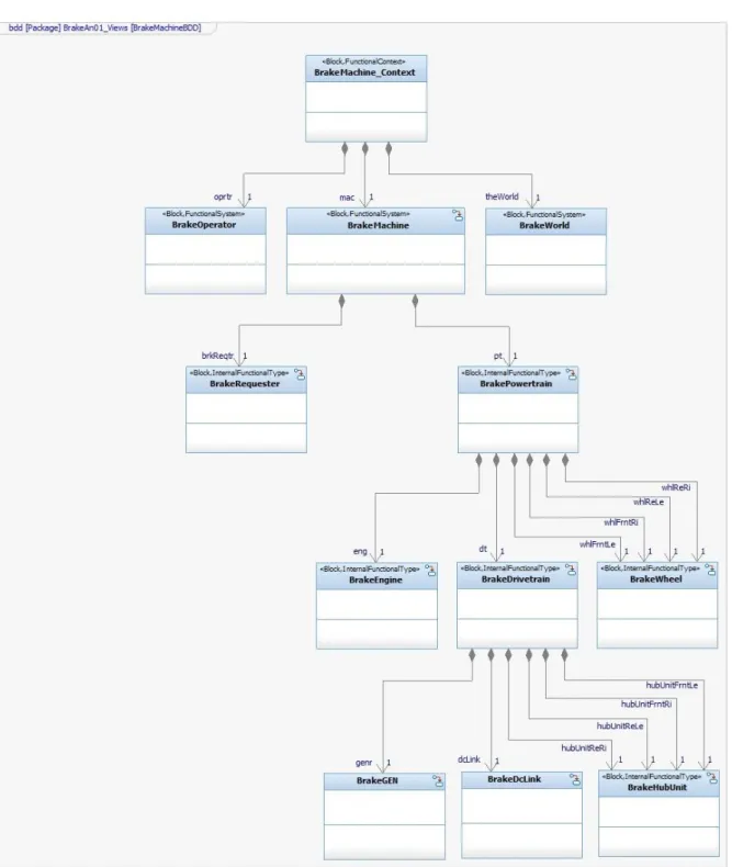
First, we will describe high level software view of “Brake” functionality, represented as Block Definition Diagram in SysML. The activity tree shows the hierarchy of activities in a Block Definition Diagram. Figure 9 representing SysML activity tree gives a very good structural overview of the system function, which is the core of each system and it is of value to understand them fully. This view is used to analyze what subsystems and components are required to realize a function that creates a braking force on the machine and gives the machine the capability to brake. Additional sub-systems and components may be required to increase the quality of the braking, but they are not shown in order to keep the view simple.
25
Figure 9 - The activity tree of “Brake” function
Operator represents a person who operates a machine by sending a braking request to
Machine through an interface.
World represents the machine environment settings, i.e. ground, temperature etc.
Machine, representing complete machine, consists of two subsystems: Requester and
different levels of abstraction
26
Powertrain is a subsystem that includes following subsystems: Engine, Drivetrain and Wheel.
Powertrain is there to link mentioned subsystems with the Requester and Machine.
Requester represents a braking pedal. This subsystem creates a propulsion torque event to the
Machine, with the return value of braking torque. Machine generates an event from Powertrain to Drivetrain through force request. Further, Powertrain generates power and delivers it to the engine, drivetrain and wheels.
Drivetrain is a subsystem which includes components that deliver power to driving wheels.
These components are represented with following subsystems: Generator, DcLink and HubUnit. Drivetrain generates reference power event for the Engine and gets the power value. Further, it forwards it to Generator.
Engine is a machine which converts heat from burning gas to the force which further enables
turning the wheels. Fuel injectors provide gas to the engine cylinder at a previously defined timed moment. Engine can be shifted between two states - ON and OFF. When Engine is in OFF state, it is not consuming/producing any power. When Driveline sends a startup request to Engine, it changes state to ON. If there is no braking request, Engine is in Idle state and it is not generating any power for braking. When Driveline sends a braking request to Engine, the engine operating point is being changed to meet that request and Engine changes its state to Transient state. If there is no change in the braking request, Engine changes its state from Transient state to Steady state and stays in that state until the change happens. Engine sends generate power request to Generator via Driveline with referent power value as an attribute.
Generator is a device with the main purpose to convert mechanical energy which is obtained
from some external source into electrical energy considered as an output. It can be in four states: OFF, Idle, Motoring and Generating. When Generator is in OFF state, power distributor and transmitter are turned off. When Driveline sends a startup request to Generator, it changes its state to Idle. It stays in Idle state as long as there is no braking request. If there is a braking request from Driveline, Generator changes its state to Motoring or Generating depends if referent power is positive or negative. If referent power is positive, Generator transforms torque from Engine to Driveline. If referent power is negative, Generator transforms power from Driveline to Engine and it acts as a motor. The important part of Generator is alternator which produces the electrical output which is further sent to DC link through Drivetrain.
DcLink represents the connection between two circuits, rectifier and inverter. Alternating
Current (AC) is electric current where the flow of charge changes direction periodically. That implies that the voltage level in AC circuits also reverses along with the current. AC waveforms are presented sinusoidally, in contrast to Direct Current (DC) waveforms which are the straight line. That is why it is easier to manipulate DC waveforms. DC is a constant flood of electrons in one direction, which provides constant voltage and current. In other words, electrons in DC circuit move from negative pole towards positive pole. DC link is used in case voltage or frequency needs to be changed. When AC power is presented to DC link, it converts to DC power by using rectifiers consist of power semiconductor components.
27
Right away, it changes to AC. The capacitor stores DC power and works together with the rectifier. DC link transmits the power in the direction determined by the load.
HubUnits transmit driveline torque and serve as a point for monitoring the speed of the wheel
loader. The main purpose of the hub is to keep the wheel rotating freely on the bearing. Hub is the only part which provides fixing plate for wheel and holds the wheel to the vehicle. Moving sideways is limited by a lock nut which is located on the outer of the sub axle. There are three possible states that hub unit can shift between: Idle, Braking and Motoring. If the electric motors are in OFF state and no braking request can be satisfied, then the hub is in Idle state. In case brakes are applied while the motors are OFF, the machine is prevented from rolling and the hub is in Braking state. After the drivetrain performs startup operation, hub units are in Idle state, but ready to take any braking request. If there is a braking request from Driveline, HubUnits change its state to Motoring or Braking depends if referent power is positive or negative.
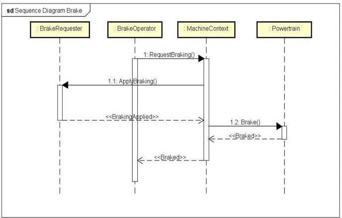
In order to better represent the braking flow we have made a following sequence diagram that describes the braking behavior of the wheel loader. It captures the transmission system behavior in response to brake requests from the operator/machine. Operator sends braking request to Machine to perform braking. Machine forwards that request to Requester, which represents a braking pedal. When Requester applies braking, Machine sends braking event to Powertrain, where braking really happens.
different levels of abstraction
28
6.2. Analyzed “Brake” function models
In this case study, we have analyzed Block Definition, Internal Block and State Machine Diagrams of “Brake” function in SysML together with “Drivetrain” system in Simulink. We used SysML models to analyze which subsystems and components are required to carry out the “Brake” function. Then, we have examined models representing the lower level of involved subsystems in Simulink.
Block Definition Diagram represents a high level description of the “Brake” system and includes all subsystems needed for realization of a braking request. Each subsystem from Block Definition Diagram is represented with Internal Block Diagrams where its own subsystems and their relationships are described.
State Machine Diagrams are used to describe the behavior of each subsystem from the Block Definition Diagram of “Brake” function. They show all the states that each subsystem goes through depending on the input values and transition conditions. Section 6.1. describes the Block Definition Diagram of “Brake” function together with the behavior of each subsystem that can be captured in corresponding State Machine Diagrams. All diagrams in SysML are simple and represent basic relationships and behavior of subsystems on the high level of abstraction. We have used Internal Block and State Machine Diagrams as a basis for understanding Simulink diagrams.
Simulink diagrams of “Drivetrain” system describe the behavior of the whole drivetrain system on the lowest level of abstraction. There are no specific diagrams of the “Brake” function, so we had to trace its behavior from the “Drivetrain” system which is very detailed and enormous. “Brake” function is consistent in multiple subsystems so the analysis of each of them was unavoidable.
Since different groups of people have been working on SysML and Simulink representations of the system, SysML and Simulink diagrams are not one-to-one related and there is naming inconsistency. Lack of documentation and naming inconsistency turned out as a considerable problem in understanding and interpreting these diagrams. Also, elements are not fully matching, since SysML describes system on a higher level of abstraction than Simulink.
29
7. Identified dependency types
Different levels of abstraction include different design entities, e.g. functions, software and hardware components. That implies that dependencies among those entities are very likely, regardless of whether we are considering abstract models or physical components. Dependencies between different levels of abstraction are mostly reflected in:
- Communication between components/functions developed or modeled at different levels of abstraction
- The analogy of components on different levels of abstraction. It is very likely to have an overlap of information among models and functions.
- Clarification of components when they are being refined into some part of the software
- The commonality of components/functions because of their reusability
SysML and Simulink diagrams of the “Brake” functionality are not one-to-one related, therefore diagrams of system parts that are related to the examined functionality are not one-to-one related and they are not represented following the same hierarchy between models. While analysing SysML and Simulink diagrams of “Brake” functionality, some general dependencies between these two different types of diagrams are found. Table 1 represents a list of found dependency types.
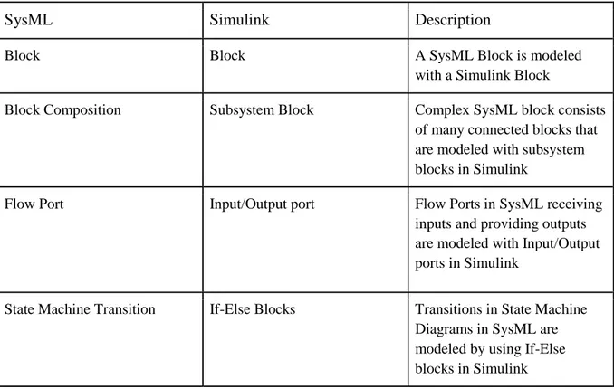
Table 1 - List of identified dependency types between SysML and Simulink models
SysML Simulink Description
Block Block A SysML Block is modeled
with a Simulink Block
Block Composition Subsystem Block Complex SysML block consists of many connected blocks that are modeled with subsystem blocks in Simulink
Flow Port Input/Output port Flow Ports in SysML receiving inputs and providing outputs are modeled with Input/Output ports in Simulink
State Machine Transition If-Else Blocks Transitions in State Machine Diagrams in SysML are modeled by using If-Else blocks in Simulink
different levels of abstraction
30
Flow Specification Bus Object Flow specification in SysML are modeled by using Bus objects in Simulink
Constraint Block Dynamic Equation SysML Constraint blocks are modeled with Dynamic Equations in Simulink, describing the link between time-dependent variables
Connector Line/Branch line Connectors in SysML are
modeled with Lines and Branch lines carrying signals in
Simulink
In the following subsections, each type of dependencies is explained and corresponding examples are given.
7.1 Block ←→ Block
While searching for connections between Simulink models and SysML models, it can be noticed that in SysML mainly everything can be defined by a block and that in Simulink everything can be defined by a block (entity), so that leads to conclusion that blocks (entities) in Simulink model can be interpreted as blocks in SysML model.
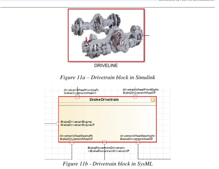
There are many examples of this dependency type and figures 11a and 11b show one of them. It can be seen that Drivetrain is represented by a block in both SysML and Simulink diagrams. However, SysML and Simulink do not consist of the same blocks, so there cannot be one-to-one relation. Simulink gives an overview of the system on the lower level and it is mostly focused on describing a behavior of the system, while SysML gives an overview of the system on the high level and its behavior diagrams do not go into details. That being said, all Simulink blocks cannot be represented with SysML blocks. Anyway, all SysML blocks of high level system description must be represented in Simulink so the consistent integration would have been achieved.
As noticed, the block in Simulink has a different name than the block in SysML, although they represent the same part. In this case, the problem is not expressed to a great extent, but if we consider a subsystem whose all blocks are named differently, the problem related to consistent integration may become huge. That is why this issue cannot be disregarded.
31
Figure 11a – Drivetrain block in Simulink
Figure 11b - Drivetrain block in SysML
7.2 Flow Port ←→ Input/Output Port
A Flow Port in SysML is a port that specifies the possible input and output flowing items between a Block and its environment across the connector. Flow Ports are interactions points through which flowing items can represent an input or an output for specific Block. Input ports are blocks in a subsystem that represent inputs to the subsystem, while output ports are blocks that represent outputs from the subsystem. These blocks are used to connect inputs and outputs of the subsystem and to provide a connection between various tasks. Flow ports correspond to input and output ports in Simulink. Since there cannot be a one-to-one relation between Simulink and SysML blocks, the one-to-one relation between flow ports and input/output ports cannot be realized as well. Having said that, multiple ports in Simulink are represented as one or more flow ports in SysML.
Example of this dependency is given in figures 12a and 12b. In figures 12a and 12b it can be seen that the interface which is responsible for data flow between Operator/User, Requester and Powertrain in SysML, is corresponding to Input ports to PowertrainControl in Simulink (marked with red color). This interface is in charge of transferring a braking force request from User to Powertrain. In the figure 12a, it can be seen that User sends brake, propulsion and brakingPropulstion request to Powertrain which are represented as input ports in Powertrain Control. On the other side, figure 12b represents the corresponding structure in SysML. It shows that User first sends brake request to Requester, which then sends received
different levels of abstraction
32
request to Powertrain. The absence of block Requester is noticeably in Simulink model of the stated functionality since User communicates with Powertrain directly. Moreover, SysML model does not specify that propulsion request is included. Those gaps are perceived and serve as an example of non consistent integration between different levels of abstraction. Modifying block Requester in SysML will surely affect the output from Requester, as well as input to Powertrain. Since that block does not exist in Simulink model, it is not possible to make an automatic conversion from SysML to Simulink, in case of modification. The same case is with SysML model and propulsion request. If that request modifies in Simulink model, the change will affect the output of the PowerTrain, but it is not specified if the change can be automatically converted to SysML model, what leads to inconsistency.
Figure 12a - Brake machine Input/Output ports in Simulink
33
7.3 Connector ←→ Line/Branch Line
The line which starts from an existing line and transfers its signal to the input port of some block in Simulink model is called branch line. Its main role is to allow carrying the same signal to more than one block. Line and branch line have corresponding elements in SysML called connectors, which can be bidirectional and unidirectional. Since there cannot be a one-to-one relation between Simulink and SysML blocks, the one-one-to-one relation between connectors lines/branch lines cannot be realized as well. Having said that, multiple connectors in Simulink are represented as one or more lines in SysML.
The connector which is responsible for data flow between Wheels and Drivetrain (as subsystems of Powertrain) in SysML, is corresponding to the line between Powertrain and Drivetrain in Simulink. This line is in charge of transferring a wheel torque from Powertrain/Wheels to Drivetrain. In the figure 13a, it can be seen that Powertrain sends wheel torque to Drivetrain which is represented as a line between these blocks. On the other side, figure 13b represents the corresponding process in SysML. Since the hierarchy of blocks is different in SysML models, and Drivetrain and Wheels are subsystems of Powertrain, there is no connection between these two blocks possessed by Powertrain like it is the situation in Simulink. Anyway, there are many other lines in Simulink diagrams that correspond to the connector between Wheels and Drivetrain.
different levels of abstraction
34
Figure 13b - Powertrain to Drivetrain and Wheels Connector in SysML
7.4 Block Composition ←→ Block Subsystems
External entities in SysML are connected through interaction point called port, which corresponds to signals between Simulink entities. As they move through the model, entities are held by blocks. Therefore, SysML model which contains blocks connected through ports representing block composition corresponds to Simulink model containing connected blocks representing subsystem block. However, the same as in Block←→Block applies here; there is no one-to-one relation between blocks. All Simulink blocks cannot be represented with SysML blocks but all SysML blocks of high level system description must be represented in Simulink so the consistent integration would have been achieved.
Figures 14a and 14b give an example of this dependency. Drivetrain block diagram consists of the composition of four Hub subsystem blocks in both SysML and Simulink diagrams. However, other different subsystems can also be found in these diagrams. Hence, other block subsystems of Drivetrain in Simulink are not one-to-one related with block composition of Drivetrain in SysML.
35
Figure 14a - Block Subsystems in Simulink
Figure 14b - Block composition in SysML
7.5 State Machine ←→ If-Else Blocks
State Machines in SysML are typically used to represent the life cycle of a block. They support the event-based behavior of the system and their main elements are the transitions and the states. If-Else blocks in Simulink implement if-else logic to control subsystem execution. SysML states can be represented as if-else blocks in Simulink. SysML states and transitions correspond to Simulink if-else blocks and lines that connect these blocks. Anyway, this is not always the case since there are finite state machines in Simulink and this behavior of the system could be represented by them as well.
different levels of abstraction
36
Figures 15a and 15b give an example of this dependency. To interpret if braking torque is actuated by the service brake or the electric motor, the function should decide whether the braking should be done by the service brake or the electric motor. How to interpret the braking torque depends on which state the hub is currently in, therefore it is important to first interpret the hub state correctly. Hub can be in three main states: braking, motoring, idle/coasting. Whether the hub state is in braking or motoring states, it depends on the current torque of the hub. If the hub torque is positive, the hub is in Braking state and braking torque is actuated by the service brake. If the hub torque is negative, the hub is in Motoring state and the braking torque is actuated by the electric motor. If the hub torque is equal to zero, the hub is in Idle/Coasting state and the braking torque is equal to zero. These hub states in SysML are represented as If-Else blocks in Simulink. Simulink model does not represent Idle/Coasting state, so whether the braking torque is actuated by the service brake or the electric motor it switches states between Braking and Motoring. Braking and Motoring states are named differently in Simulink models.
Figure 15a - If-Else blocks in Simulink
37
7.6 Constraint block ←→ Dynamic equation
A dynamic equation in Simulink specifies the relationship between time-dependent variables. On the other side, SysML uses constraint blocks to model boolean constraint expressions. Constraint parameters take their values from the value properties which are being constrained and they correspond to the mentioned variables described by dynamic equations in Simulink.
7.7 Flow properties ←→ Bus object
In order to access the Bus or select specific signals from the Bus, signals need to be combined to a Bus signal. A Bus can have an associated Bus object which is used to define a structure of the bus and features of its elements. On the other side, in SysML, set of flow properties, inputs and outputs are listed using flow specification, which corresponds to Bus object in Simulink.
different levels of abstraction
38
8. Discussion
The purpose of this case study was to observe different dependency types that exist in SysML and Simulink models. Correspondences between SysML and Simulink models have been found. Using these correspondences, we have found dependencies between mentioned models and made a list of dependency types. We have examined examples of each type and have noticed following:
- Multiple Input/Output ports in Simulink correspond to one flow port in SysML - Multiple lines in Simulink correspond to one connector in SysML
- Blocks in SysML and Simulink are not one-to-one related
- Blocks in SysML and Simulink do not include the same subsystem blocks - One block in SysML corresponds to multiple blocks in Simulink
Items from the list above affect the consistent integration of the system. These items represent gaps between SysML and Simulink diagrams.
Multiple Input/Output ports in Simulink correspond to one flow port in SysML - The
problem that arises in this case is related to the potential modification of flow port in SysML or input/output ports in Simulink. If there is a change in data that is transferred by the flow port it is hard to know which input/output ports are affected by the change. Hence, the automatic conversion between SysML and Simulink models is complicated to achieve.
Multiple lines in Simulink correspond to one connector in SysML - The problem that arises
in this case is similar to the previous case. If there is a change in one connector in SysML it is impossible to know which lines are affected by that change in Simulink. Therefore, the automatic conversion between SysML and Simulink is complicated to achieve in this case as well.
Blocks in SysML and Simulink are not one-to-one related - The problem that arises in this
case is related to different blocks in SysML and Simulink. For example, some blocks exist only in Simulink but don’t exist in SysML (and vice-versa). For consistent integration and automatic conversion between SysML and Simulink, it is crucial that at least main blocks are the same.
Blocks in SysML and Simulink do not include the same subsystem blocks - The problem
that arises in this case is similar to the previous one. Subsystem blocks in SysML and Simulink are not one-to-one related and some subsystem blocks in SysML and Simulink are included in different blocks. Hierarchy of blocks is not the same in SysML and Simulink.
One block in SysML corresponds to multiple blocks in Simulink - Similar to previous cases,
there is a problem in consistent integration and automatic conversion between SysML and Simulink in this case, too.
39
Since elements in models are not one-to-one related, e.g. it is not clearly stated if input/output ports in Simulink are part of flow port in SysML, it is highly suggested to include documentation in both models and in that way improve consistency between Simulink and SysML models. Also, naming inconsistency between these models and its elements was noticed. In order to clearly see the overlap of elements in Simulink and SysML models, names need to be compatible. That is very useful because using different names for elements reflect on analogy in different abstraction levels. Ideally, all corresponding models should be one-to-one related and that is what should be strived to. Since SysML represents a high-level view of the system, SysML models with its belonging components must be represented in Simulink.
![Figure 3 - Example of BDD [10]](https://thumb-eu.123doks.com/thumbv2/5dokorg/4881243.133519/11.892.106.788.101.558/figure-example-of-bdd.webp)
![Figure 4 - Example of IBD [10]](https://thumb-eu.123doks.com/thumbv2/5dokorg/4881243.133519/12.892.289.606.520.691/figure-example-of-ibd.webp)
![Figure 7 - Abstraction layers in EAST-ADL [3]](https://thumb-eu.123doks.com/thumbv2/5dokorg/4881243.133519/15.892.225.688.478.808/figure-abstraction-layers-east-adl.webp)