HYDRIDE-INDUCED EMBRITTLEMENT IN
METALS – STRESS AND TEMPERATURE
EFFECTS
A.G. Varias
Materials Science, Technology and Society, Malmö University, SE-205 06 Malmö, Sweden
A.R. Massih
Quantum Technologies AB, Uppsala Science Park, SE-751 83, Uppsala, Sweden
Materials Science, Technology and Society, Malmö University, SE-205 06 Malmö, Sweden
Abstract A robust mathematical model for the hydrogen embrittlement of hydride forming
metals has been developed. The model takes into account the coupling of the operating physical processes, namely: (i) hydrogen diffusion, (ii) hydride precipitation, (iii) non-mechanical energy flow, and (iv) hydride/solid-solution deformation. Crack growth is simulated by using a new version of de-cohesion model with time-dependent energy of de-cohesion due to the gradual process of hydride formation.
Zircaloy-2 hydrogen embrittlement and fracture initiation have been studied by using a finite element implementation of the model. Delayed hydride cracking has been considered in two configurations: (i) a semi-infinite crack, under mode-I K-field dominance and constant temperature, and (ii) a cracked plate, under tensile stress and temperature gradient. The initial and boundary conditions, in case (ii), are those encountered in the fuel cladding of boiling water reactors, during operation, and lead to loss of K-field dominance soon after the application of loading. The numerical simulation predicts hydride precipitation at some distance from the crack tip. The near-tip hydride platelets fracture, when the remote loading is sufficiently strong, and leave behind ligaments, which are stretched plastically, in agreement with experimental observations. The numerical results on hydride size, incubation period and crack growth velocity are compared with experimental data.
Further development of the model should be combined with accurate experimental determination of the mechanical and thermal properties of the hydrides.
1. INTRODUCTION
The stimulation of the present study is coming from nuclear industry, where zirconium alloys are used in several structural parts of a nuclear reactor core. Zirconium alloys combine good mechanical and neutron-absorption properties. However, hydrogen embrittlement occurs during service, mainly at extended fuel burnup (usage), and may lead to significant reduction in fracture toughness. Indeed, hydrogen is generated due to the oxidation of zirconium by the coolant water in the reactor. Subsequently hydrogen diffuses in the material and forms hydrides, when its terminal solid solubility is exceeded. The hydride is a brittle phase, which actually causes the embrittlement of the material. Then, delayed hydride cracking, a subcritical crack growth mechanism, may occur, e.g. [2]-[4], [7], [11].
Hydrogen embrittlement, caused by the formation of hydrides at stress concentration locations, has been also observed in electron-microscope studies of vanadium, niobium and titanium [14], [1], [6], [12].
The hydride-induced embrittlement results from the simultaneous operation of several coupled processes, namely, (i) hydrogen diffusion, (ii) hydride precipitation, (iii) non-mechanical energy flow, and (iv) hydride/solid-solution deformation. A simulation of the embrittlement mechanism at constant temperature, i.e. by taking into account the coupling of processes (i), (ii) and (iv) has been presented recently by Lufrano, Sofronis and Birnbaum [8]-[9]. However, the heat transfer process within a nuclear reactor core leads to the development of temperature gradient in the fuel cladding and significantly affects material deterioration. A mathematical model, which takes into account all processes (i)-(iv) as well as hydride fracture for the simulation of crack growth, has been developed by Varias and Massih [15], [17]. The model is based on the thermodynamic theory of irreversible processes and takes into account hydrogen thermal transport. The time-dependent fracture toughness of the material ahead of the crack tip, due to the gradual hydride precipitation, is also taken into account in a new version of the de-cohesion model for crack growth. A brief discussion of the embrittlement/fracture model follows. Details of the model and relevant references are given in [15], [17].
2. HYDRIDE INDUCED EMBRITTLEMENT AND
FRACTURE MODEL
The governing equations of all operating physical processes are presented. Hydrogen diffusion is simulated by enforcing the conservation of hydrogen mass:
k H k HT x J dt dC ∂ ∂ − = , (1) where HT
C is the total hydrogen concentration and JiH are the components of hydrogen flux. CHT is related to the concentration of hydrogen in the solid solution,
H
C , and the hydride, CH,hr, as follows: H hr H HT C f fC C = , +(1− ) , (2)
where f is the hydride volume fraction. Note that H
C is equal to the hydrogen terminal solid solubility, TS
C , when f ≠ 0, while CH,hr can be considered constant, independent of temperature. Also hydrogen diffusion in the hydride is significantly slower than in the metal and therefore it can be neglected. Then, the following relation provides the total hydrogen flux in a hydride/solid-solution composite:
+ − − = k H k H H H H k x Q x R C D f J ∂ ∂ ∂ ∂µ T T T ) 1 ( . (3)
Here R is the gas constant and T is the absolute temperature. Also H D
and H
Q are
the diffusion coefficient and the heat of transport of hydrogen in the solid solution, respectively. Hydrogen thermal transport is taken into account by the temperature gradient term. The effects of stress and hydrogen concentration on diffusion are both included in the gradient of the chemical potential of hydrogen in the solid solution,
H µ : − + = ijkl ij kl mm H H H M V σ σ σ µ µ 3 1 2 1 0 , , (4)
where µH,0 is the stress free hydrogen chemical potential, which depends on
hydrogen concentration. In the present study the law for ideal solutions is adopted. H
V is hydrogen molal volume. Also Mijkl and σij are metal’s elastic compliance and stress tensor, respectively.
The precipitation of the hydride (MHx) occurs under chemical equilibrium
conditions, when the terminal solid solubility of hydrogen in the metal, CTS, is reached: − + = ijkl ij kl mm H acc TS TS M R V R w w C C σ σ σ 2 1 3 T exp T x exp int 0 , , (5) where TS,0
C is the terminal solid solubility of hydrogen, under stress-free conditions. Hydrides expand during precipitation and, consequently, the solubility of hydrogen is affected by the strain energy of hydride accommodation, wacc, as well as by the interaction energy of the applied stress field with the expanding hydride, w . Bothint
acc
w and w are defined per mole of hydride.int
The non-mechanical energy flow is governed by the following differential equation, which is derived by enforcing conservation of energy:
n H H n i i hr hr p x J x k x dt df V H dt d c ∂ ∂µ ∂ ∂ ∂ ∂ ρ − = ∆ + T T , (6)
where ρ, c and k are the density, the specific heat at constant pressure and thep thermal conductivity of the metal, respectively. Also ∆Hhr and hr
V are the enthalpy associated with the formation of a mole of hydride and the hydride molal volume, respectively. Therefore the variation of the heat content in the metal–hydride composite depends on conducted heat, heat generated during hydrogen diffusion and heat released during hydride formation.
The deformation of the hydride/solid-solution composite is coupled with hydrogen diffusion and energy flow due to the strains, which are caused by hydrogen dissolution, hydride formation and thermal expansion:
− − = − dt d dt d dt d M dt d E kl H kl kl ijkl ij ε ε ε σ 1 , (7)
(
)
[
hr H M H]
ij H ij V C f f dt d dt d θ θ δ ε − + = 1 3 1 , (8) dt d dt d ij E ij T αδ ε = , (9)where θhr is the trace of hydride expansion strain tensor and H H M
V V =
θ is the
expansion of the metal lattice due to hydrogen dissolution. M
V and α are the molal volume and the thermal expansion coefficient of the metal. It is assumed that the elastic and thermal properties of the hydride and the solid solution are identical.
Hydride fracture and therefore crack growth is simulated by considering cohesive tractions along the crack path. All information on material damage (i.e. void growth in the metal and hydride cleavage) is contained in the distribution of cohesive traction. At a material particle along the crack path, cohesive traction is related to the respective normal displacement through a simple trapezoid variation. The energy of de-cohesion, i.e. the energy required per unit crack advance, and the maximum cohesive traction are given by the following relations:
(
)
M hr f f 0 0 0 φ 1 φ φ = + − , (10) 2 2 max fσhr (1 f)σM σ = + − . (11) Here M 0 φ and hr 0φ are the de-cohesion energies, when there is no hydride and when there is only hydride, along the crack plane, respectively. hr
0
φ is derived from the threshold stress intensity factor of delayed hydride cracking, hr
I
K , [15];
( )( )
KhrI Ehr 2 2
0 1 ν
φ = − , where E, ν are Young’s modulus and Poisson’s ratio of the material. Similarly, M
0
φ is derived from the critical stress intensity factor of the metal, M
I
K . Also σhr is hydride fracture strength and σM is equal to three times the yield stress of the metal [15]. Note that the elastic-plastic behavior of the metal has been considered in the derivation of de-cohesion constitutive relations, in order to accurately predict the strong effect of hydrostatic stress on hydrogen diffusion.
In the following the hydrogen embrittlement and fracture model is applied to irradiated Zircaloy-2. The material properties are given in Table 1.
Table 1. Material properties used in the finite element calculations. The material properties correspond to irradiated Zircaloy-2 and δ-hydride (ZrH1.66) [17]. CTS is an experimentally
derived terminal solid solubility under no applied stress.
ν , E 80.4 GPa, 0.369 hr σ 580 MPa M σ 1740 MPa M I K 30+0.045(T-300) MPa√m hr I K 3.22+0.02205(T-300) MPa√m H D 2.17×10⁻⁷exp(-35087.06/RT) m2/s H Q 25122 J/mole TS C 6.3741×10⁵exp(-34542.75/RT) mole/m3 hr H C , 1.02×10⁵ mole/m3 H V 7×10⁻⁷ m3/mole M V 14.0×10⁻⁶ m3/mole hr V 16.3×10⁻⁶ m3/mole hr θ 0.1636 H θ 0.05 x 1.66 ρ 6490 kg/m3 hr H ∆ -63517.41 J/mole k 9.37683+0.0118T W/ mK p c 226.69+0.206639T-6.4925×10⁻⁵T2 J/kgK α 5.96×10⁻⁶ K-1
3. HYDRIDE PRECIPITATION AND FRACTURE UNDER
K-FIELD DOMINANCE
A semi-infinite crack is considered in a homogeneous material under mode-I loading and plane strain conditions. K-field traction is applied on a semi-circular boundary of radius equal to 0.1 m; only half of the space is analyzed, due to symmetry with respect to the crack line. The stress intensity factor initially increases at a rate equal to 0.2 MPa√m⋅s-1 for 100 s and subsequently remains constant at the maximum
value of 20 MPa√m. The temperature of the material is equal to 300o C. Initial total
hydrogen concentration is equal to 6438.5 mole/m3 (≈1000 ppm). The material is
assumed to be insulated by a zirconium oxide layer and consequently zero hydrogen flux is prescribed along the crack face and the remote semi-circular boundary. Due to symmetry conditions, hydrogen flux is also taken equal to zero along the crack line. A Cartesian coordinate system is considered with origin at the crack tip and x1-axis
f 1
x
(µm) 0.0 0.2 0.4 0.6 0.8 1.0 0 10 20 30 40 50 S e?? ? 1 S e?? ? 2 S e?? ? 3 S e?? ? 40
2=
x
t (days) 1/864 14
4.36
1
x
(µm) ∆t=t-tinc (s) 0 2 4 6 8 1 0 0 2 0 4 0 6 0 8 0 1 0 0 1 2 0right tip of microcrack
left tip of microcrack a)
b)
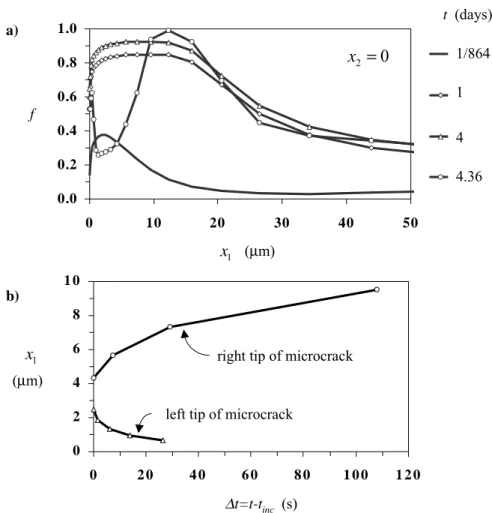
Fig. 1. (a) Hydride volume fraction distribution along the crack line and (b) microcrack propagation, under K-field dominance; tinc=4.36 days.
The progress of hydride precipitation with time is presented in Fig. 1a. At t = 4 days, hydride volume fraction, f, is greater or equal to 0.90 within the range of 2.5 µm ≤ x1 ≤12.4 µm. The development of the area ahead of the crack tip, which is rich in
hydride volume fraction, can be interpreted as the precipitation of near-tip hydrides of size about equal to 10 µm, in agreement with the interstriation spacing and the hydride platelet size, observed in delayed hydride cracking experiments [2], [7], [3]. At t = 4.36 days, the hydride volume fraction is relatively small ahead of the crack tip over a distance of the order of 10 µm. A new hydride volume fraction peak develops further away. Also there is a small region of about half a micron at the crack tip, where f is larger than 0.5. This redistribution of hydride volume fraction has been produced within about 100 s and it is attributed to the fracture of the near tip hydrides and the associated decrease of the near tip hydrostatic stress. Thus a micro-crack has been generated ahead of the main crack tip, leaving behind a thin ligament, which is expected to fail in a ductile mode, due to the relatively small hydride volume fraction
(0.5<f<0.65). Therefore the present numerical simulation is in agreement with the development of striations during delayed hydride cracking (e.g. [2], [3]). According to Fig. 1b, the generated micro-crack propagates 8.88 µm, within the time period of 107.8 s, at an average speed of 8.24×10⁻⁸ m/s. Note that the micro-crack average speed does not correspond to the crack growth rate of stage II delayed hydride cracking, since we have simulated only the first cycle of the crack growth process. However, it is expected, that a variation of the average micro-crack speed, due to different material parameters, corresponds to a similar variation of the stage II crack growth rate.
The above calculations have been performed for hr I
K equal to 9.24 MPa√m,
which is an experimentally derived threshold stress intensity factor for delayed hydride cracking of irradiated Zircaloy-2. According to the experimental data of Huang and Mills [7], the threshold stress intensity factor for delayed hydride cracking decreases when the density of the hydride habit planes in the crack plane increases. Material texture affects also stage II crack growth rates. The crack growth rate increases with the density of the hydride habit planes in the crack plane. Therefore, by varying hr
I
K in the present model, texture effects could be implicitly taken into
account. Indeed, crack growth calculations with hr =1.63 I
K MPa√m show that the
average micro-crack speed is doubled. The above threshold stress intensity factor is derived without the consideration of matrix plastic deformation, by using a cohesive zone model [16].
Efsing and Pettersson [3] measured, recently, a stage II crack growth rate equal to 9.5×10⁻⁷ m/s; the irradiated Zircaloy-2 specimens had initial hydrogen concentration between 560 and 1900 ppm and were tested at 300o C. Also, the incubation period varied between 16 and 24 hr. However, before testing, the specimens were subjected to a thermal cycle in order to promote crack growth; the specimens were kept at a higher temperature for a few hours, before the application of the loading. According to Simpson and Puls [13], when specimens are cooled to the test temperature the relatively small hydrides that form and grow during this excursion are more susceptible to dissolution, due to high elastic constraint, and this enhances the driving force for hydrogen diffusion into the crack-tip process zone. Note that, in the present simulation, the initial hydrogen concentration is assumed to be uniform, associated with an unconstrained material expansion, which does not lead to the development of residual stresses. The above mentioned temperature effect on crack growth could be introduced by considering a non-uniform initial hydrogen concentration which should be also associated with an initial non-zero and non-uniform stress distribution.
4. HYDROGEN EMBRITTLEMENT IN A CRACKED
PLATE UNDER NO K-FIELD DOMINANCE
The effect of surface cracks on hydrogen embrittlement in the cladding of light water reactor fuel rods is investigated. The most critical case corresponds to a crack along the rod axis. Indeed, during reactor operation, the fuel pellet-cladding mechanical interaction is the major source of loading and may lead to the development
of significant tensile hoop stresses [10]. The expansion of zirconium oxide on the waterside of the cladding may also produce tensile hoop stresses.
0 .0
0 .1
0 .2
0 .3
0 .4
0 .5
0 .6
0 .7
0
2
4
6
8
1 0
S e?? ? 1 S e?? ? 2 S e?? ? 3 S e?? ? 4 S e?? ? 50 .0
0 .4
0 .8
1 .2
1 .6
2 .0
0
1 00 2 00 3 00 4 00 5 00 6 00 7 00
S e?? ? 1 S e?? ? 2 S e?? ? 3 S e?? ? 4 S e?? ? 5t (days)
1
2
3
4
5
t (days)
1
2
3
4
5
a)
b)
ap kkσ
σ
f
1x
(
µ
m)
1x
(
µ
m)
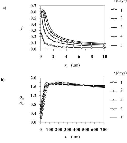
Fig. 2. (a) Hydride volume fraction and (b) stress trace distributions along the crack plane in a plate under tensile loading and temperature gradient.
A cracked plate is a good approximation of a cladding tube with an axial crack. The plate thickness, w, is taken to be equal to the actual cladding wall thickness (in this case w=0.8 mm). A long planar surface crack, of depth a (= 0.1w), has been considered on one side, which corresponds to the waterside of the cladding. A remote tensile stress, σap, is applied normal to the crack faces and builds up gradually, at a rate of 10 MPa/s, up to the maximum value of 500 MPa. Zirconium oxidation is assumed to produce a constant inflow of hydrogen on the crack-side surface of the plate and the crack faces, which is equal to 0.122×10⁻⁷ mole/(m2⋅s) [5]. A zero
hydrogen flux is considered on the other side of the plate, where stress and temperature gradients do not allow hydrogen outflow. The surface temperature is constant, being equal to 567 K, on the crack side, and 607 K, on the other side (i.e. the fuel side) [5]. The initial temperature distribution is assumed to be linear across the thickness of the plate. The initial hydrogen concentration is equal to 2500 mole/m3
(≈388 ppm), which corresponds to 1900 days of reactor operation. Symmetry conditions require that the heat and hydrogen fluxes on the crack plane as well as on the remote plane, where σap is applied, are zero. Plane strain conditions prevail. A Cartesian coordinate system is considered with origin at the crack tip and x1-axis
parallel to the crack plane.
a) b) 0.0 0.2 0.4 0.6 0.8 1.0 0 10 20 30 40 50 S e?? ? 1 S e?? ? 2 S e?? ? 3 S e?? ? 4 t
50 s
1 hr
2 hr
2.28 hr
f ∆t=t-tinc (s) 0 2 4 6 8 10 12 0 50 100 1 50 200
right tip of microcrack left tip of microcrack
0
2=
x
1 x (µm) 1 x (µm)Fig. 3. (a) Hydride volume fraction distribution along the crack line and (b) microcrack propagation, in a cracked plate under tensile stress and temperature gradient; CHT(t=0)=
20000 mole/m3,
inc
t =2.28 hr.
Figures 2a and 2b show the distribution of hydride volume fraction and normalized stress trace along the crack plane, respectively. Note that after 5 days of load application steady-state conditions are approached. According to Fig. 2b, there is
no region of K-field dominance, due to hydrogen thermal transport to the waterside of the cladding. Therefore, linear elastic fracture mechanics cannot be used in integrity calculations. However, according to Fig. 2a, severe material embrittlement is limited only to a very small area near the crack tip and no crack growth is expected in the case under consideration. Indeed the finite element calculations show no unloading along the crack plane.
The numerical calculations were repeated for a crack length equal to a quarter of the cladding wall thickness (a=0.25w) as well as for a Zircaloy-2 toughness, which is by 25% smaller than the value given in Table 1; the selection of the new value of the fracture toughness is in agreement with the scatter in the experimental data. Four cases of initial hydrogen concentration were considered: 2500, 6438.5, 9657.7 and 20000 mole/m3, which are about equal to 388, 1000, 1500 and 3200 ppm, respectively. Crack
growth initiation was only predicted for the extreme case of 3200 ppm. Figure 3 shows the development of the near-tip hydride region and the respective microcrack propagation. The microcrack propagated 10.34 µm over a period of 174.80 s at an average speed of 5.91×10⁻⁸ m/s. The extreme hydrogen concentration was actually observed in places of the fuel cladding, where the oxide layer was partially lost due to spalling, during service. In this case, according to experiments, crack growth may occur.
Acknowledgments
A.G. Varias acknowledges the support of ABB Atom AB under the contracts 4500026874 and 4500028097. Financial support for the study on hydride induced embrittlement in metals is currently provided by the Foundation for Knowledge and Competence Development (Project Grant Hög 2000, KK-Stiftelsen, Sweden).
References
1. Birnbaum, H.K., Grossbeck, M.L. and Amano, M. Hydride precipitation in Nb and some properties of NbH, Journal of the Less-Common Metals 49 (1976) 357-370.
2. Dutton, R., Nuttall, K., Puls, M.P. and Simpson, L.A. Mechanisms of hydrogen induced delayed cracking in hydride forming materials, Metallurgical Transactions A 8 (1977) 1553-1562.
3. Efsing, P. and Pettersson, K. Delayed hydride cracking in irradiated Zircaloy cladding, in
Zirconium in the Nuclear Industry: Twelfth International Symposium, ASTM STP 1354,
edited by Sabol, G.P. and Moan, G.D., American Society for Testing and Materials, 2000, pp. 340-355.
4. Efsing, P. and Pettersson, K. The influence of temperature and yield strength on delayed hydride cracking in hydrided Zircaloy-2, in Zirconium in the Nuclear Industry: Eleventh
International Symposium, ASTM STP 1295, edited by Bradley, E.R. and Sabol, G.P.,
American Society for Testing and Materials, 1996, pp. 394-404.
5. Forsberg, K. and Massih, A.R. Redistribution of hydrogen in Zircaloy, Journal of Nuclear
6. Grossbeck, M.L. and Birnbaum, H.K. Low temperature hydrogen embrittlement of Niobium II – Microscopic observations, Acta Metallurgica 25 (1977) 135-147.
7. Huang, F.H. and Mills, W.J. Delayed hydride cracking behavior for Zircaloy-2 tubing,
Metallurgical Transactions A 22 (1991) 2049-2060.
8. Lufrano, J., Sofronis, P. and Birnbaum, H.K. Elastoplastically accommodated hydride formation and embrittlement, Journal of the Mechanics and Physics of Solids 46 (1998) 1497-1520.
9. Lufrano, J., Sofronis, P. and Birnbaum, H.K. Modeling of hydrogen transport and elastically accommodated hydride formation near a crack tip, Journal of the Mechanics
and Physics of Solids 44 (1996) 179-205.
10. Massih, A.R., Rajala, T. and Jernkvist, L.O. Analysis of pellet-cladding mechanical interaction behaviour of different ABB Atom fuel rod designs, Nuclear Engineering and
Design 156 (1995) 383-391.
11. Sagat, S., Chow, C.K., Puls, M.P. and Coleman, C.E. Delayed hydride cracking in zirconium alloys in a temperature gradient, Journal of Nuclear Materials 279 (2000) 107-117.
12. Shih, D.S., Robertson, I.M. and Birnbaum, H.K. Hydrogen embrittlement of a titanium: in situ TEM studies, Acta Metallurgica 36 (1988) 111-124.
13. Simpson, L.A. and Puls, M.P. The effect of stress, temperature and hydrogen content on hydride-induced crack growth in Zr-2.5Pct Nb, Metallurgical Transactions A 10 (1979) 1093-1105.
14. Takano, S. and Suzuki, T. An electron-optical study of β-hydride and hydrogen embrittlement of vanadium, Acta Metallurgica 22 (1974) 265-274.
15. Varias, A.G. and Massih, A.R. Simulation of hydrogen embrittlement in zirconium alloys under stress and temperature gradients, Journal of Nuclear Materials 279 (2000) 273-285. 16. Varias, A.G. and Massih, A.R. Temperature and constraint effects on hydride fracture in
zirconium alloys, Engineering Fracture Mechanics 65 (2000) 29-54.
17. Varias, A.G. and Massih, A.R. Hydride-induced embrittlement and fracture in metals – effect of stress and temperature distribution, Journal of the Mechanics and Physics of
![Table 1. Material properties used in the finite element calculations. The material properties correspond to irradiated Zircaloy-2 and δ-hydride (ZrH 1.66 ) [17]](https://thumb-eu.123doks.com/thumbv2/5dokorg/3950323.73900/5.892.240.657.271.718/material-properties-calculations-material-properties-correspond-irradiated-zircaloy.webp)