Civil Engineering Journal
Vol. 5, No. 12, December, 2019Behavior of Reinforced Concrete Beams with effect of Stiffened Plates
Ali Sabah Al Amli
a, b*, Laith Shakir
c, Ali Abdulredha
d, Nadhir Al-Ansari
b a Al-Mustansiriyah University, Palestine Street, 10052 Baghdad, Iraq.b Lulea University of Technology, 971 87 Lulea, Sweden. c University of Karbala,56001Karbala, Iraq. d University of Warith AL-Anbiya’a,56001 Kerbala, Iraq.
Received 31 May 2019; Accepted 19 September 2019
Abstract
This study presents experimental work including an investigation conducted on five simply supported reinforced concrete beams under pure torsion. First beam without strengthening as a control beam. The other four beams were strengthened externally by bolted thin steel plates. For this test the load was applied gradually. The torque was increased gradually up to failure of the beam. The variables were the thickness and height of the steel plate that was externally connected to both sides of the rectangular reinforced concrete beam. The test results for the beams discussed are based on torque-twist behavior. The experimental results show that the attachment of thin steel plates by mechanical means to beams provides a considerable improvement in the torsional behavior of the reinforced concrete beams. Comparable to the reference beam, the maximum increase in the cracking and the ultimate torque of the composite beam was recorded for the reinforced concrete beam that strengthen by steel plate of 150 mm height, 2 mm thickness and 50 mm spacing between shear connectors (B1). The results revealed that the cracking torque, ultimate torque, global stiffness of beam and beam ductility for all composite beams increase with the increase of the plate's thickness, plate's height.
Keywords: Torque; Reinforced Concrete; Steel Plate; Strengthening, Beams.
1. Introduction
The torsion effects were omitted from the design of reinforced concrete structures for many years. In 1958 ACI committee 438 had made recommendations for suitable torsion design requirement [1]. As a result of these efforts, the ACI-318 Building Code [2] was inserting a new form of torsion design criteria at 1971 for the first time.
Before cracking of reinforced concrete members under torsional moment, there was perceivable effect on the stiffness from reinforcement. As the same, an additional strength beyond the plain concrete capacity can be gain from the longitudinal or transverse reinforcement [3].
First cracking torque is commonly increased, when the longitudinal and the transverse steel are combined. According to the value and location of the reinforcement, a considerable increase in strength and a large amount of plastic torque are possible in spite of stiffness reducing after cracking moment [4].
Fang and Shiau [5] presented experimental results of torsional behavior for normal and high strength concrete beams (NSC and HSC, respectively). Different values of reinforcement were used, subjected to pure torsion. The experimental results demonstrated that the high strength concrete beams owned higher cracked stiffness and torsional strength than
* Corresponding author: ali.sabah@ltu.se
http://dx.doi.org/10.28991/cej-2019-03091433
© 2019 by the authors. Licensee C.E.J, Tehran, Iran. This article is an open access article distributed under the terms and conditions of the Creative Commons Attribution (CC-BY) license (http://creativecommons.org/licenses/by/4.0/).
the normal concrete beams fabricated with the same amount of reinforcement. After the ultimate strength, the high strength beams showed relatively a high decay in strength than the normal strength beams high reinforcement design.
The torsional capacity of peak point on rectangular beams section with both spiral and tied reinforcements in the torsion direction and its anti-direction was investigated by Barghlame and Lotfollahi-Yaghin [6]. The tests showed that the prismatic beam with spiral links has lower torsion capacity than the tied ones.
Ghobarah et al. [7] performed an experimental test on using fiber reinforced polymer (FRP) to enhance the torsion strength of reinforced concrete beams. It was observed that the using wrapping configuration were very effective especially for fully wrapped beams which give behavior better than the beams reinforced with stirrups. It was shown from all the tests, the applicability of using FRP to improve the torsional resistance of reinforced concrete beams.
Panchacharam and Belarbi [8] concluded that, the cracking and the ultimate torsional capacity were significantly improved by strengthening the reinforced concrete beams with externally GFRP sheets.
A nine reinforced concrete beams strengthened with an external GFRP fabrics were executed under the torsional moments by Tudu [9]. Different patterns with different kinds of GFRP fabrics were distributed on eight beams, while the ninth one represents control beam. The results deduced that using GFRP fabrics as external stiffening can enhance the torsional capacity of beams greatly, also the results showed that the best GFRP fabrics patterns is the full wrap. As well as adding GFRP in 45° with longitudinal axis of beams shows high strength than the applied ones in 90° with beam axis.
In this study only square beams subjected to pure torsional moment are investigated. Thin steel plates attached to a reinforced concrete beam by means of mechanical connectors. The function of these connectors is to transfer the forces between the two components.
The aim of the current work is to investigate the different thicknesses and heights of steel plate on the behavior of reinforced concrete beams strengthened with steel plates under pure torsion. The cracking torque, ultimate torque, mode of failures, and angle of twist of the beams are discussed through this study. Many researches were studied the behavior of beams with many sections, materials, reinforcement and repairing with the Torque effect [10-14].
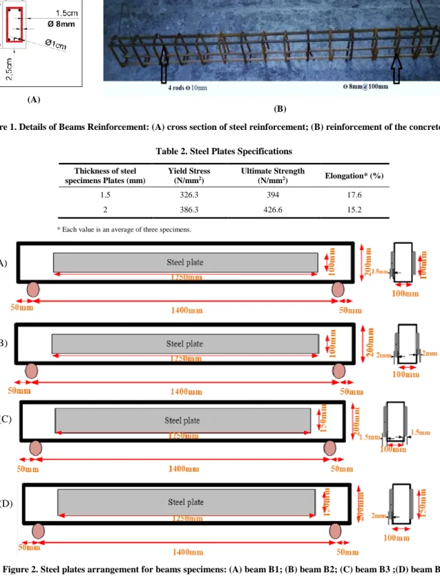
The experimental procedure consists of testing five composite reinforced concrete-steel beams subjected to pure torsion. One of which used as the control beam without plate (BN) , the other four beams with steel plates of two different thicknesses (1.5 mm and 2 mm) were subjected to monotonic loading. All the beams tested have the same dimensions: 100 mm width, 200 mm depth and 1500 mm length. The compressive cubic strength of all tested beams was about (30MPa) at age of (28) days. The steel reinforcements ratio used in all the composite concrete-steel beams were similar (ρ= 0.91%), while the spacing of closed stirrups is 100mm c/c. The variables studied through the procedure test were the thickness and height of the externally attached steel plate: B1 strengthened externally with steel plate of 2 mm thickness and 150 mm height, B2 strengthened externally with steel plate of 1.5 mm thickness and 150 mm height, B3 strengthened externally with steel plate of 2 mm thickness and 100 mm height, and B4 strengthened externally with steel plate of 1.5 mm thickness and 100 mm height.
Two deformed steel bars diameters are used through this investigation, the first one is (10mm) which are used for the main reinforcement and the second steel bars is (8mm) which are used for stirrups as shown in Figure 1. From the results, the adopted steel bars conformed to (ASTM A615-86) [15] as shown in Table 1. While two different steel plates thicknesses of (1.5, 2) mm were used to strengthen the composite reinforced concrete beams, which the properties are shown in Table 2, and the material properties [20]. Figure 2 shows the steel plates arrangement for beams specimens. Many previous researches studied the effect of torque [16-25]. This study is very important to increase the torque capacity to the beams. Also, this method can used to repairing the beams or increase the stiffness of them. When the capacity increased, the structure with these beams is suitable in design and don’t need rehabilitation in the future; thus, good for the cost.
Table 1. Steel Reinforcing Bar Specification and Test Results
Diameter Bar (mm) Measured Diameter (mm) Yield Stress * (N/mm2) Ultimate Strength (N/mm2) Elongation % 8 8 496 612.9 17 10 10 521 615.7 19
(A)
(B)
Figure 1. Details of Beams Reinforcement: (A) cross section of steel reinforcement; (B) reinforcement of the concrete beam
Table 2. Steel Plates Specifications
Thickness of steel specimens Plates (mm) Yield Stress (N/mm2) Ultimate Strength (N/mm2) Elongation* (%) 1.5 326.3 394 17.6 2 386.3 426.6 15.2
* Each value is an average of three specimens.
Figure 2. Steel plates arrangement for beams specimens: (A) beam B1; (B) beam B2; (C) beam B3 ;(D) beam B4
2. The Procedure of Test
The procedure of tests (The Methodology) is expressed as following:
All beams were tested under monotonically increasing torque up to failure. For this test the load was applied gradually.
The torque was increased gradually up to failure of the beam; Figure 3 shows the test setup.
The Universal Testing Machine model (8551 MFL system) with a maximum capacity of 300 tons was used to apply the torsional moment on the tested beams with a structural arrangement shown in the Figure 4.
The proposed arrangement of test was conducted by Zararis and Penelis [26]. (A)
(B)
(C)
The rigid clamping loading frame on each end of the tested beam used in this study.
The torque is satisfied by the arms with separated faces to connect them over the sample with four large bolts for each arm, while a steel girder of 250 mm depth and 2500 mm length was used to transmit the loads from the center of the universal machine to the two arms (pure torsion) as shown in Figure 4.
Two dial gauges tied to the bottom fiber of the end of the beam at a point 35 mm from the center of the longitudinal axis were used to estimate the angle of twist, Figure 5. Two dial gauges, the first one on the right and the other on the left, recorded the uplift and downward values to estimate the twist angle.
Figure 3. The Test Setup [26]
Figure 4. Beam Testing Arrangement
(A) (B)
3. Experimental Results
3.1. Effect of Steel Plate Height on Torsional Behavior
To understand the effect of steel plate height on the reinforced concrete beams strengthened with steel plates, two heights (100 and 150 mm) were used in the current work. Tables 3 and 4 describe the general test results for the reinforced beams, whereas the effects of plate height on the torsional resistance of the tested beams are covered by Figures. 7 to 10.
Test results indicate that the steel plate height made a good contribution to the crack and ultimate torque resistance, where both the cracking and ultimate torque increased as the height of the steel plate increased. The tested beams attached to the steel plate of 100 mm in height exhibited an increase in cracking and ultimate torques (from 124% to 200% and 151% to 222% for steel plate thickness 1.5 and 2 mm respectively) compared with the reference beam (BN). Better enhancement in both cracking and ultimate torques was recorded for the composite beams of 150 mm plate height (from 200% to 250% and 204% to 278% for steel plate thickness 1.5 and 2 mm respectively) in comparison with the reference beam (BN). It can be noticed that all beams connected to steel plate of 150 mm in height were stronger than the other beams, while the weakest beam was the reference beam without a steel plate (BN).
Tests for the torque versus angle of twist, which explains the effect of the steel plates’ height on the tested beams, were constructed, as shown in Figures 7 and 8. At higher loads, it was found that, for the same loading values, the increase in the plate height will decrease the angle of twist significantly due to increasing the area under the curve (stiffness) and the energy absorption capacity (ductility). A possible reason for this increment in the stiffness and ductility is due to contribution of the steel plate, as steel is a ductile material and therefore, as the height of the steel plate was increased, the ductility and stiffness of the concrete beams increase, which is a very desirable feature for safer design. At the same torsional moment (7.5 KN.m), the angle of twist was decreased from 0.294˚ to 0.196˚; this decrease in the angle of twist is due to the effect of increasing the steel plate area, as shown in Figure 7.
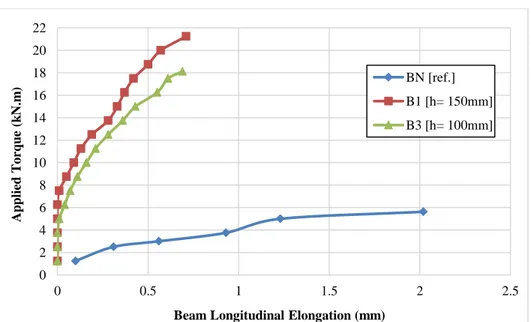
It was concluded from Figures 9 and 10 that the steel plate height made a good contribution for decreasing the longitudinal elongation of the composite beams. From all the results, the height of steel plate increased the torsion capacity to the beams. Since, the height of plate increases the stiffness of beam, and that make the beams give the high strength with applied torque.
Table 3. Cracking Torque Results for the Experimentally Tested Beams
Beam No. Plate Thickness mm Plate Height mm Bolt Spacing Mm Cracking Torque (KN.m) Angle of Twist (deg./m) Percent of Torque increase % BN --- --- --- 2.50 0.261 --- B1 2 150 50 8.75 0.335 250 B2 1.5 150 50 7.5 0.376 200 B3 2 100 50 7.5 0.294 200 B4 1.5 100 50 5.62 0.32 126
Table 4. Ultimate Torque Results for the Experimentally Tested Beams.
Beam No. Plate Thickness mm Plate Height mm Bolt Spacing Ultimate Torque (kN.m) Angle of Twist (degree/m) Percent of Torque increase % BN --- --- --- 5.62 5.945 --- B1 2 150 50 21.25 6.33 278 B2 1.5 150 50 17.125 4.053 204 B3 2 100 50 18.125 4.606 222 B4 1.5 100 50 14.125 3.433 151
Figure 6. Torque- Twist Relationship of R.C Beams of 2 mm Plate Thickness
Figure 7. Torque- Twist Relationship of R.C Beams of 1.5 mm Plate Thickness
Figure 8. Torque- Longitudinal Elongation Relationship of R.C Beams of 2 mm Plate Thickness 0 2 4 6 8 10 12 14 16 18 20 22 0 0.5 1 1.5 2 2.5 Ap p li ed To rq u e (k N.m )
Beam Longitudinal Elongation (mm)
BN [ref.] B1 [h= 150mm] B3 [h= 100mm] 0 2 4 6 8 10 12 14 16 18 20 22 0 0.5 1 1.5 2 2.5 3 3.5 4 4.5 5 5.5 6 6.5 Ap p li ed To rq u e (k N.m )
Angle of Twist (degree/m)
BN [ref.] B1 [h=150mm] B3 [h=100mm] 0 2 4 6 8 10 12 14 16 18 20 22 0 0.5 1 1.5 2 2.5 3 3.5 4 4.5 5 5.5 6 6.5 Ap p li ed To rq u e (k N.m )
Angle of Twist (degree/m)
BN [ref.] B2 [h=150mm] B4 [h=100mm]
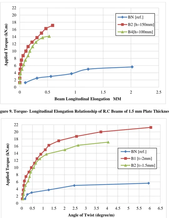
Figure 9. Torque- Longitudinal Elongation Relationship of R.C Beams of 1.5 mm Plate Thickness
Figure 10. Torque- Twist Relationship of R.C Beams of 150 mm Plate Height
3.2. Effect of Steel Plate Thickness on Torsional Behavior
Figures 11 to 14 show the effect of plate thickness on the beams’ torsional behavior. It was obvious from the general test results that the overall properties of the beams are enhancing when the plate thickness increases, where both the cracking and ultimate torque increased as the thickness of the steel plate increased. The tested beams attached to steel plate of 1.5 mm thickness exhibited an increase in cracking and ultimate torques (from 124% to 200% and 151% to 204% for the 100 and 150 mm plate height respectively) compared with the reference beam (BN). Better enhancement in both cracking and ultimate torques was recorded for the composite beams of 2 mm plate thickness (from 200% to 250% and 222% to 278% for the 100 and 150 mm plate height respectively) in comparison with the reference beam (BN). It can be noticed that all the composite concrete-steel beams connected to 2 mm-thick steel plate were stronger than the other composite beams connected to 1.5 mm-thick steel plate.
The influence of the steel plate's thickness on the torque-twist response is shown in Figures 11 and 12. In these figures it founds that, during the early loading stage, the torque-twist behavior of the composite beams was almost the same but with little decrease in the angle of twist due to the increase in plate thickness, and this continued until the applied torque equated the first crack torque approximately. Then, the angle of twist would decrease significantly with the increase in loading due to the global stiffness and ductility of the composite beams increasing with an increase in the steel plate's thickness. As seen in Figure 11, when increasing the steel plate’s thickness from 1.5 mm in B2 to 2 mm in B1 at the same torsional moment (7.5 KN.m), the angle of twist was decreased from 0.367˚ to 0.196˚.
0 2 4 6 8 10 12 14 16 18 20 22 0 0.5 1 1.5 2 2.5 Ap p li ed To rq u e (k N.m )
Beam Longitudinal Elongation MM
BN [ref.] B2 [h=150mm] B4[h=100mm] 0 2 4 6 8 10 12 14 16 18 20 22 0 0.5 1 1.5 2 2.5 3 3.5 4 4.5 5 5.5 6 6.5 Ap p li ed To rq u e (k N.m )
Angle of Twist (degree/m)
BN [ref.] B1 [t=2mm] B2 [t=1.5mm]
The relationship between longitudinal strain and torsional moment is shown in Figures 13 and 14. Based on these figures, it can be concluded that the steel plate made a good contribution for decreasing the longitudinal elongation of the tested beams. From all the results, the thickness of steel plate increased the torsion capacity to the beams. Since, the thickness of plate increases the stiffness of beams, and that make the beams give the high strength with applied torque.
Figure 11. Torque-Twist Relationship of R.C Beams of 100 mm Plate Height
Figure 12. Torque- Longitudinal Elongation Relationship of R.C Beams of 150 mm Plate Height
Figure 13. Torque- Longitudinal Elongation Relationship of R.C Beams of 100 mm Plate Height
0 2 4 6 8 10 12 14 16 18 20 22 0 1 2 3 4 5 6 Ap p li ed To rq u e (k N.m )
Angle of Twist (degree/m)
BN [ref.] B3 [t=2mm] B4 [t=1.5mm] 0 2.5 5 7.5 10 12.5 15 17.5 20 22.5 0 0.5 1 1.5 2 2.5 Ap p li ed To rq u e (k N.m )
Beam Longitudinal Elongation (mm)
BN [ref.] B1[t=2mm] B2 [t=1.5mm] 0 2 4 6 8 10 12 14 16 18 20 22 0 0.5 1 1.5 2 2.5 Ap p li ed To rq u e (k N.m )
Beam Longitudinal Elongation (mm)
BN [ref.] B3 [t=2mm] B4 [t=1.5mm]
Figure14. Torque-Longitudinal Elongation Relationship of R.C Beams of 100 mm Plate Height
4. Conclusions
Based on the results obtained from the experimental work, the following conclusions are presented.
It can be concluded that the use of steel plates that are mechanically attached to both sides of the reinforced concrete beams under torsional load enhances the overall properties of these members.
It was shown that, as the thickness of the 100mm steel plate connected to the reinforced concrete beam increased from 1.5 mm to 2 mm, the ultimate torsional moment increased by an average of 28%; also, the cracking torsional moment increased by an average of 33.5%.
It was shown that, as the height of the steel plate connected to the reinforced concrete beam increased from 100 mm to 150 mm, the ultimate torsional moment increased by an average of 21.2%; also, the cracking torsional moment increased by an average of 33.5% for the 1.5mm steel plate thick.
The global stiffness and ductility of the composite beams increased significantly as the thickness and the height of the steel plate increased.
5. Conflicts of Interest
The authors declare no conflict of interest.
6. References
[1] Hsu, TTC. “Torsion of Reinforced Concrete.” Van No strand Reinhold Company (May 1984).
[2] ACI Committee 318, “Building Code Requirements for Reinforced Concrete (ACI 318-71).” ACI Journal Proceedings 68, no. 8 (January 1972). doi:10.14359/15231.
[3] Al-Saraj, W.K., “Structural Behavior of Reinforced Reactive Powder Concrete T-Beams under Pure Torsion.” Ph.D. Thesis, Civil Engineering, College of Engineering, Al-Mustansiriyah University (July 2013).
[4] Zia, Paul. “Torsion Theories for Concrete Members.” American Concrete Institute18 (January 1968): 103-132
[5] Fang, I.K., and Shiau J.K. “Torsional Behavior of Normal- and High-Strength Concrete Beams.” ACI Structural Journal 101, no. 3 (June 2004): 304-313. doi:10.14359/13090.
[6] Barghlame, Hadi, and M. A. Lotfollahi-Yaghin. "Investigating the Capacity of Ultimate Torsion of Concrete Prismatic Beams with Transverse Spiral Bars." World Academy of Science, Engineering and Technology, International Journal of Civil, Environmental, Structural, Construction and Architectural Engineering 5, no. 11 (2011): 561-566.
[7] Ghobarah, A., M. N. Ghorbel, and S. E. Chidiac. "Upgrading torsional resistance of reinforced concrete beams using fiber-reinforced polymer." Journal of composites for construction 6, no. 4 (2002): 257-263. doi:10.1061/(ASCE)1090-0268(2002)6:4(257).
[8] Panchacharam, Saravanan, and Abdeldjelil Belarbi. "Torsional behavior of reinforced concrete beams strengthened with FRP composites." In First FIB Congress, Osaka, Japan, vol. 1, pp. 01-110. 2002.
0 2 4 6 8 10 12 14 16 18 20 22 0 0.5 1 1.5 2 2.5 Ap p li ed To rq u e (k N.m )
Beam Longitudinal Elongation (mm)
BN [ref.] B3 [t=2mm] B4 [t=1.5mm]
[9] Arun Kumar,U., Bhargavi ,V., Raghava Rao ,E. “Study of Torsional Behavior of Rectangular Reinforced Concrete Beams Wrapped With GFRP International Journal of Research Publications In Engineering And Technology 2 (December 2015):1-6. [10] Saad, Redhaab Hamed, and Ali Sabah Ahmed. "Behavior of Composite I-Section Modified Reactive Powder Concrete Beams
with Ultimate Torque." Journal of Engineering and Sustainable Development 20, no. 6 (November 2016): 55-67.
[11] Al Amli, A.S. Mehdi, H.A and Ahmed, R.H. “Cracks torque of T section R.C. beam with web Perforation using reactive powder concrete.” IJCSEIE RD 6 (Jun 2016):21-28.
[12] Ahmed, Ali Sabah. "Behavior of Repaired Composite Modified Reactive Powder Concrete I-Section Beams With Opening under Pure Torque." Journal of Engineering and Sustainable Development 21, no. 1 (January 2017): 39-50.
[13] Al Amli, Ali Sabah Ahmed, Nadhir Al-Ansari, and Yaarub G. Abtan. “Behavior of Repairing Composite I-Section Beams with Opening Under Ultimate Torque.” Engineering 10, no. 04 (2018): 202–214. doi:10.4236/eng.2018.104014.
[14] Ali Sabah Al Amli, Nadhir Al-Ansari, and Sabah Jasim Dahboosh Shejiri. “Repairing of RC T-Section Beams with Opening by CFRP for Cracks and Ultimate Torque.” Journal of Civil Engineering and Architecture 12, no. 2 (February 28, 2018). doi:10.17265/1934-7359/2018.02.001.
[15] American Society for Testing and Materials (ASTM), “Standard Specification for Deformed and Plain Carbon – Steel Bars For Concrete Reinforcement”, ASTM A615/A615M (January 2015).
[16] Abebe, Beka, and Jong Lee. “Incorporation of Torsional & Higher-Mode Responses in Displacement-Based Seismic Design of Asymmetric RC Frame Buildings.” Applied Sciences 9, no. 6 (March 15, 2019): 1095. doi:10.3390/app9061095.
[17] Arvind Kumar, Madan Mohan, Rajesh, D., and Prathik Kulkarni. “Behaviour of Fibre Reinforce Concrete Beam in Pure Torsion.” International Journal of Research in Engineering and Technology 04, no. 05 (May 25, 2015): 551–556. doi:10.15623/ijret.2015.0405102.
[18] Atea, Rafid Saeed. “Torsional Behavior of Reinforced Concrete T-Beams Strengthened with CFRP Strips.” Case Studies in Construction Materials 7 (December 2017): 110–117. doi:10.1016/j.cscm.2017.03.002.
[19] Aziz, Ali, and Oday Hashim. “Torsional Strength Evaluation of Reinforced SCC Box Beams Strengthened Internally by Opened and Closed Transverse Concrete Diaphragms.” Edited by T.S. Al-Attar, M.A. Al-Neami, and W.S. AbdulSahib. MATEC Web of Conferences 162 (2018): 04009. doi:10.1051/matecconf/201816204009.
[20] Ahmed, Ali Sabah, and Ali abdulrazaq Abdulredha. "Effect of Spacing between Shear Connectors on the Behavior of Composite Concrete Steel Beams under Pure Torsion." Journal of Engineering and Sustainable Development 19, no. 4 (2015): 246-261. [21] Bernardo, Luís. “Modeling the Full Behavior of Reinforced Concrete Flanged Beams Under Torsion.” Applied Sciences 9, no.
13 (July 5, 2019): 2730. doi:10.3390/app9132730.
[22] Ma, Shengqiang, N. Muhamad Bunnori, and Kok Keong Choong. “Prediction of Ultimate Torque of Reinforced Concrete Box Beam Bonded with CFRP Strips.” KSCE Journal of Civil Engineering 22, no. 11 (July 16, 2018): 4353–4363. doi:10.1007/s12205-018-0872-2.
[23] Mondal, Soumen, Sushanta Ghuku, and Kashi Nath Saha. “Effect of Clamping Torque on Large Deflection Static and Dynamic Response of a Cantilever Beam: An Experimental Study.” International Journal of Engineering and Technologies 15 (November 2018): 1–16. doi:10.18052/www.scipress.com/ijet.15.1.
[24] Kang, Chongjie, Steffen Hartwig, and Steffen Marx. "Behavior of externally prestressed segmental towers' dry joint under torsion effects." Structural Concrete 20, no. 4 (March 2019): 1350-1357. doi:10.1002/suco.201800266.
[25] Bunyamin. “Comparison of Deflection of Hollow Block Concrete Blocks with Normal Reinforced Concrete Beam” Proceedings Article (January 2019). doi:10.1063/1.5085982.
[26] Zararis, P. D., and G. Gr Penelis. "Reinforced concrete T-beams in torsion and bending." ACI Journal 83, no. 1, (January 1986): 145-155.
![Figure 3. The Test Setup [26]](https://thumb-eu.123doks.com/thumbv2/5dokorg/5489203.142910/4.892.246.634.160.1059/figure-the-test-setup.webp)