http://www.diva-portal.org
This is the published version of a paper presented at ASME Turbo Expo 2019:
Turbomachinery Technical Conference and Exposition, GT 2019, 17 June 2019 through 21 June 2019.
Citation for the original published paper:
Xin, Z., Sahoo, S., Kyprianidis, K., Sumsurooah, S., Valente, G. et al. (2019) A framework for optimization of hybrid aircraft
In: Proceedings of the ASME Turbo Expo American Society of Mechanical Engineers (ASME)
https://doi.org/10.1115/GT2019-91335
N.B. When citing this work, cite the original published paper.
Permanent link to this version:
A FRAMEWORK FOR OPTIMIZATION OF HYBRID AIRCRAFT
Xin Zhao, Smruti Sahoo and Konstantinos Kyprianidis
Mälardalen University Västerås, Sweden
xin.zhao@mdh.se
Sharmila Sumsurooah, Giorgio Valente, Mohamed Rashed, Gaurang Vakil and
Christopher Ian Hill University of Nottingham
Nottingham, UK
christopher.hill@ieee.org Claire Jacob, Andreas Gobbin
and Andreas Bardenhagen Technische Universität Berlin
Berlin, Germany
andreas.bardenhagen@tu-berlin.de
Katrin Prölss and Michael Sielemann
Modelon Deutschland GmbH, Munich, Germany
michael.sielemann@modelon.com
Jonatan Rantzer and Edward Ekstedt
Modelon AB Lund, Sweden
jonatan.rantzer@modelon.com
ABSTRACT
To achieve the goals of substantial improvements in efficiency and emissions set by Flightpath 2050, fundamentally different concepts are required. As one of the most promising solutions, electrification of the aircraft primary propulsion is currently a prime focus of research and development. Unconventional propulsion sub-systems, mainly the electrical power system, associated thermal management system and transmission system, provide a variety of options for integration in the existing propulsion systems. Different combinations of the gas turbine and the unconventional propulsion sub-systems introduce different configurations and operation control strategies. The trade-off between the use of the two energy sources, jet fuel and electrical energy, is primarily a result of the trade-offs between efficiencies and sizing characteristics of these sub-systems. The aircraft structure and performance are the final carrier of these trade-offs. Hence, full design space exploration of various hybrid derivatives requires global investigation of the entire aircraft considering these key propulsion sub-systems and the aircraft structure and performance, as well as their interactions.
This paper presents a recent contribution of the development for a physics-based simulation and optimization platform for hybrid electric aircraft conceptual design. Modeling of each sub-system and the aircraft structure are described as well as the aircraft performance modeling and integration technique. With a focus on the key propulsion sub-systems, aircraft structure and performance that interfaces with existing conceptual design
frameworks, this platform aims at full design space exploration of various hybrid concepts at a low TRL level.
INTRODUCTION
A consideration for the reduction of the aircraft operation related environmental footprint is the key driver for future development in the aviation sector. To this requirement, European Flightpath 2050 policy has established a vision for year 2050, for a 75% reduction in CO2 emissions per passenger kilometer, a 90% reduction in NOx emissions, and a reduction of 65% in noise emission, relative to the capability of aircraft for base year 2000 [1]. The reduction in CO2 emissions are majorly aimed to be achieved (68% out of 75%) from improvements in airframe and propulsion system technology [2]. Preliminary studies indicated a limited gain can be achieved from the improvement in the structure and material for the airframe [3]. This limitation demands a huge efficiency gain from the improvement in propulsion system.
Overall, advancement in the existing conventional technologies has resulted in 15% more efficient new generation of aircraft for the present market, such as A320neo and B737max families. However, an average annual increase rate of 5% on the volume of the air transportation is neutralizing the benefit from the net gain in emission reduction. As shown in Figure 1, a schematic CO2 emissions reduction roadmap published by IATA in 2013 suggested a big gap between the known aircraft technologies and the target in a long-term perspective [4]. This gap must be filled by radical and fundamentally different
Proceedings of ASME Turbo Expo 2019: Turbomachinery Technical Conference and Exposition GT2019 June 17-21, 2019, Phoenix, Arizona, USA
Figure 1 Schematic CO2 emissions reduction roadmap [4] concepts. Among the most promising technologies, in a short
term, conventional aircraft/engine technologies, such as geared turbofan, ultra-high bypass ratio turbofan, composite structures for wing and fuselage, are still dominate the vision. For the longer-term future, however, more radical technologies in aircraft and engine, such as box wing design, blended wing design, open rotor, hybrid propulsion and full electric propulsion are showing more potential [5].
The introduction of electrical energy to the major propulsion unit of the aircraft has triggered extensive research for exploration of different architectural topologies: broadly classified as universally-electric or hybrid-electric architecture [6-8]. The potential benefits of the full electric powered aircraft configurations have been widely explored by NASA and Bauhaus Luftfart [8-15]. However, in particular for large aircraft applications, one of the most critical obstacles for full electric propulsion is the current electrical energy storage system technology. This is predicted to not reach the required levels prior to year 2045 [6]. Having said that, hybrid propulsion is considered as a more feasible compromise solution for a greener flight in the near future and has become the cornerstone for major research work.
The research exploration of hybrid aircraft was largely focused on the conceptual level, studying for the feasibility of the hybrid aircraft, with an end objective of benchmarking desirable technology for the electrical system components [7, 16-23]. Benefit varies as per the technology level assumption and for differing degrees of hybridization, given mission range and payload requirement. The desired technology improvement is mostly expected from the improvement in specific power/specific energy of the electrical energy storage system
[19, 20]. Nonetheless, efficiency of the other system components has cascading effects on the sizing of the energy storage system and therefore also plays paramount role [24]. Furthermore, limited public information was found in hybrid aircraft study from the gas turbine perspective. Lents C. et al. [22] in their parallel hybrid engine conceptual design reported 2.3% cruise SFC reduction through adapting the engine to a 2.1 MW electrical boost at take-off. Similar work has been carried out by Raffaelli L. et al. [25] for turbofan engine optimisation utilising electric energy storage. In addition, research were also focused on the key technology drivers for the airborne application in the future years [26-29].
Extensive possibilities are introduced when unconventional propulsion sub-systems are considered on-board aircraft. However the most common unconventional sub-systems normally considered for a typical hybrid aircraft propulsion are the electrical power system, the power transmission system and the thermal management system. Different combinations of the gas turbine and the unconventional propulsion sub-systems result in different configurations and operation control strategies. In general, the trade-off between the use of the two energy sources, jet fuel and electrical energy, is primarily a result of the trade-offs between efficiencies and sizing characteristics of the sub-systems, both conventional and unconventional. Whilst the resulted change in the aircraft frame, due to different design alternatives of the sub-systems on board, has to be captured with reasonable installation considerations. In the end, the overall effect on the aircraft performance needs to be evaluated through a mission assessment. An optimal design of any hybrid configuration can only be realized if all the above-mentioned trade-offs and interactions are correctly established. Given that,
aiming at full design space exploration of various hybrid concepts at a low TRL level, the presented framework is based on physics-based models.
In the following sections, the modelling of the propulsion sub-systems, aircraft structure and mission assessment are described separately. The integration technique used in the design framework is then presented. Finally, an integration example, based on a parallel hybrid configuration which has been established within the framework, is detailed. This example shows the methodology utilized to assemble the descried models into a specific configuration using the presented integration technique. Key specific interfaces between the models are highlighted. Illustrative results are shown in order to demonstrate the current progress and the potential of the framework. NOMENCLATURE
BPR Bypass ratio
CPACS Common Parametric Aircraft Configuration Scheme
DLR German Aerospace Center EIS Entry into service
EM Electrical motor Epol Polytropic efficiency EPS Electrical power system FPR Fan pressure ratio GA Genetic algorithm
GT Gas turbine
GTF Geared turbofan
HPC High pressure compressor HPT High pressure turbine
IATA International air transport association IGBT Insulated Gate Bipolar Transistors IPC Intermediate pressure compressor Li-S Lithium Sulphur
LPT Low pressure turbine
MOSFET Metal-Oxide Semiconductor Field Effect Transistors
MTOW Maximum take-off mass MZFM Maximum zero fuel mass OPR Overall pressure ratio PEC Power electronics converter
PM Permanent magnet
PR Pressure ratio
PRn Pressure ratio split exponent SFC Specific fuel consumption SFN Specific thrust
SiC Silicon carbide TF Technology factor
T/O Take-Off
TOC Top of climb
TRL Technology readiness level VcoldQhot Jet velocity ratio, ideal WBG Wide Band Gap
SUBSYSTEMS MODELLING Gas turbine
In the near future, it is still commonly believed that the gas turbine will be the major source of the aircraft propulsion power, hence jet fuel will still be utilised, even in a hybrid aircraft. Movements towards a high degree of hybridization start from decoupling the gas turbine from the accessory power demand set e.g. aircraft electronics, engine accessories, cabin pressurization, air conditioning and icing protection, etc. Typically, power offtake from the gas turbine shafts and customer air bleed requirement from the compressors can be removed from the engine conceptual design phase. This replacement largely reduces the engine complexity and the resulted fuel burn benefit can be observed by the use of any conventional gas turbine conceptual design tool. On the other hand, the added complexity to the electrical power system has to be realized.
Hybridization power transmission considerations
For a higher degree of hybridization, normally meaning the hybridization of the main propulsion power, conventional gas turbine modelling tool may satisfy the need of the basic configurations without major modifications. A pure parallel hybrid configuration would require the minimum effort as the mechanism of the conventional power offtakes can be utilized for conceptual design. This is, however, limited to a low TRL capability since a megawatts level power transmission is excessively higher than the power offtakes of the current engines. Looking at the pure serial hybrid configuration, as the mechanical connection between the engine core and the fan is eliminated, power transmission considerations will be taken on two aspects mainly - shaft power from the engine core to the generator and shaft power from the motor to the propulsor. For both the core and the propulsor, better performance can be expected as the desired shaft speed and corrected mass flow are achievable.
More complex configurations are basically different combinations of the two mentioned above having different hybridization modes for different flight conditions. Given that, conventional gas turbine modelling tool is sufficient to include the power transmission considerations for hybrid propulsion. Conceptual design considerations
Typically, conventional aircraft gas turbine conceptual design involves the optimization of a number of key performance parameters for minimum specific fuel consumption (SFC). These key parameters, named specific thrust (SFN), overall pressure ratio (OPR), jet velocity ratio (VcoldQhot) and pressure ratio split exponent (PRn), have been utilized for the study of the advanced engine core concepts by the authors in [30, 31]. Generally speaking, a higher OPR gives a higher thermal efficiency but with the drawbacks of increased turbine cooling and decreased compressor blade height in the end of the compression process. For a given thermal efficiency designing an engine with a lower SFN could result in a higher propulsive efficiency but limited up to the point where increased engine weight and nacelle drag outweigh any fuel burn benefit. Optimal
VcoldQhot in the range of 0.8 to 0.85, as an important indicator for the transfer efficiency, is widely suggested by the authors in [31-33]. For optimal fuel burn, the value varies for different mission setup and engine weight estimation methods. The decision for the pressure ratio split exponent is more complicated as it is strongly affected by the detailed design of the compressors and turbines. Moving more compression work to the compressor with higher efficiency potential is beneficial for SFC, however, a small change in the turbomachinery design may end up with a reduced number of compressor/turbine stage with a slightly lower thermal efficiency.
Considering a hybrid propulsion system, dominated by the gas turbine still, the above-mentioned key parameters are applicable. However, additional design variables, mainly the power transmitted between the gas turbine and the motor and their speed connection, must be added.
Gas turbine modelling within the framework
Within the framework, the gas turbine modelling involves the performance calculation, sizing and weight estimation of the gas turbine for the selected hybrid configurations. For engine performance prediction, a pre-developed tool described in [34-36] is used. The tool comprises various modules covering in substantial detail a wide range of disciplines: engine performance, engine aerodynamic and mechanical design, aircraft design and performance, emissions prediction and environmental impact, engine and airframe noise, as well as production, maintenance and direct operating costs, as illustrated in Figure 2. At this stage, the engine performance and aircraft performance are integrated to the framework. Related studies in future aero engine conceptual design performed by the tool are [30, 31, 37-39].
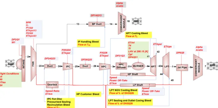
A schematic of the engine performance model established in the tool is illustrated in Figure 3, which is showing
a geared turbofan (GTF), one of the state-of-the-art engine architectures. The modelling was primarily established on the use of generic compressor and turbine characteristics, and empirical correlations as illustrated in [32]. Component characteristics were scaled based on the approach outlined in [40] at the hot-day top-of-climb (TOC) condition; nozzle throat areas were also determined at the same operating condition. Off-design matching was achieved using the generic matching procedure presented in [41]. All thermodynamic calculations were based on the assumption of an ideal gas. Simplified approach presented in [42] was used for the calculations of the high pressure turbine (HPT) thermal barrier coating average external surface blade metal temperature and corresponding cooling flows.
Figure 2 Gas turbine conceptual design tool [34]
Figure 3 Performance model schematic of a geared turbofan
For the sizing and weight estimation of the gas turbine within the framework, simplified process of estimating engine component dimensions and weight was used. After the engine performance model has been setup, empirical correlations based on the aerodynamic design point data were used to size the engine core component by component, from fan to the low pressure turbine (LPT) [43, 44]. With the sizing results, weight estimation of the engine was then largely built on the calibration of public domain information available for the existing engines [45] and methods described in [46, 47].
Electrical power system
The Electrical Power System (EPS) consists of three elements: Electrical Machine (EM), Power Electronics Converter (PEC) and Battery. The related models are described in the next three paragraphs.
Electrical machine modelling within the framework
Performance targets of electrical machines typically depend on the specific application. In the automotive industry, for instance, the available volume is often limited, hence the power to volume ratio (kW/L) is the key figure to be maximised. On the other hand, the aerospace industry is more focused upon maximisation of the power to mass ratio (kW/kg) due to its direct relationship to fuel consumption.
A Permanent Magnet (PM) machine has been selected as the machine topology investigated within the framework.PM machines are well known for their greater power density and efficiency compared to alternative topologies. They are therefore considered to be good candidates for aerospace applications [48]. Furthermore, the topology considered includes a Halbach magnetized surface PM array installed on the rotor in order to further increase the machine power density and enhance the machine performance. As a result, a hollow rotor structure can be adopted, reducing the machine mass, and providing a more sinusoidal flux density in the machine air gap which reduces both torque ripple and machine iron losses [49].
The EM modelling is achieved by exploiting an in-house design tool developed at the University of Nottingham [50]. The tool utilises a Genetic Algorithm (GA) and generates an optimized machine design once the specifications are provided. Targeting the minimization of overall machine mass, both active and inactive mass are considered. It is important to note that the latter can be as high as 34% of the total machine mass [51], therefore including the inactive mass in the overall kW/kg optimization results in higher power density machine. A multi-domain calculator, considering electromagnetic, thermal and mechanical design, is included in the design tool in order to fully evaluate the machine designs.
The EM model provides sizing and mass estimation for the electrical machine together with performance and loss calculation. EM designs are computed with the design tool considering a per-unit length. The required power can then be obtained by adjusting the machine length; as the power is proportional to the length [52].
The EM model relies on in-built lookup tables, therefore a finite power range had to be considered. Within this framework the EM rated power spans from 200 to 2000 kW, the lower limit being defined as the minimum electrical power required by the on-board auxiliary systems, while the upper limit is set in order to limit the maximum current flowing in the EM having fixed the voltage level of the electrical network and the machine insulation.
Power Electronics Converter modelling within the framework The Power Electronic Converter (PEC) is an essential component within hybrid electric aircraft. It is required for energy conversion from AC to DC power and vice versa. PECs enable the control of Electrical Machines by regulating the frequency and amplitude of the voltage applied at the machine input terminals [52, 53].
Semiconductor devices are the main building block of PECs. Conventional semiconductor devices are the Metal-Oxide Semiconductor Field Effect Transistors (MOSFET) and Insulated Gate Bipolar Transistors (IGBT) [52]. Emerging Wide Band Gap (WBG) semiconductor devices, such as Silicon carbide (SiC) devices, provide superior switching and thermal performance, but they are only available in bespoke, suboptimal packages which are not suitable for high power applications [54]. In addition, conventional devices have a temperature limit of 150 oC, while WBG semiconductor devices are expected to operate at higher temperatures, therefore require less cooling and hence result in smaller thermal systems - WBG semiconductor devices are therefore a promising future technology which could achieve high efficiency, high power density PECs. It is predicted that, due to these and other advances, by the year 2035 the power density of PECs will be up to 26 kW/kg with efficiencies of around 98 to 99.5% [55]. For the framework described here, current PEC technologies are considered, however the implemented approach allows for future technologies to be incorporated when available.
The PEC model for this framework is constructed utlising a modular design. The PEC model is designed around two modules of 200 kW and a 500 kW respectively, each module having its own design specifications based on current technology levels. A modular approach is utilized for three main reasons. First, the basic modules can be arranged in parallel and series in multi-level configuration to cater for the operating voltage and current of the system [54]. Secondly, for aerospace applications modularity allows for easier maintenance, faster time to manufacture and assemble, and introduces increased redundancy when required. Third, this approach allows for future technologies to be incorporated once available by replacing or editing the specifications of the 200kW and 500kW modules.
The PEC model aims to give realistic sizing, mass and performance estimations for the PEC given the requirements received from the EM and Mission models over a given flight mission. The PEC model receives the power requests over the entire flight mission, identifies the maximum power required within the power profile, and then uses this maximum value as the nominal power rating for design. Depending on the rated
power of the PEC, the algorithm chooses the power rating of the individual PEC modules as well the total number of modules needed. The weight and volume of the PEC are determined based on the corresponding specific power density and power density of the chosen PEC modules respectively. Further, the power loss from the designed PEC is obtained from the efficiency values of the given modules.
The thermal management of the PEC modules is done through liquid cooled cold plates that are connected to the thermal system of the aircraft system. The cold plates are modelled based on the parameters of standard cold plates from Manufacturer datasheets and they include mass flow rate and thermal resistance.
The final output from the PEC model is the combination of the weight and volume estimates for the core semiconductor modules, control boards, cabling and required cold plates.
Battery modelling within the framework
Energy storage technology remains one of the main challenges to be addressed for the advancement of the hybrid electric aircraft. The performance of the battery is dependent to a great extent on the material used [55]. Lithium ion batteries are the main current technology being used in transportation applications due to their relatively high energy density, power density, life cycle, and efficiency. In [56], the authors reported on five commercial Lithium Iron Phosphate batteries that achieve specific energy density of up to 0.13 kWh/kg, specific power density of up to 0.4 kW/kg and efficiency of up to 96.3%. Lithium Sulphur (Li-S) batteries can reach specific energy densities of up to 0.52 kWh/kg (970 kWh/m3) and power density of 1.23 kW/kg (2300 kW/m3) at the cell level according to [57]. The specific energy density of Lithium air batteries may have specific energy densities of up to 1 kWh/kg [55]. However, in order for hybrid or fully electric flight to become a reality these technologies must improve significantly.
The thermal management of batteries is a crucially important aspect of their design and operation since temperature affects both the performance and the life of the battery. At low temperatures, below -10oC, the energy and power capabilities of a battery is known to diminish, while too high a temperature may negatively affect the life time of the battery [58]. The desired operating range of Lithium ion batteries for optimum performance is considered to be between 25oC and 40oC as reported in [58]. Within the framework being developed, the lower and upper temperature limits of the Battery model have been set as 20oC and 60oC respectively. There are different methods for cooling the battery, including both air and liquid cooling. The Battery model within this framework utilises liquid cooled cold plates that are connected to the thermal network of the overall aircraft system.
The choice of the battery is also dependent on the requirement of the application. Designs may require batteries with high energy capacity and/or high power density. For the framework described here, the battery model allows differing values for specific energy/power to be utilized in order to
consider both current and future technologies. This is utlised in the results and discussions section below.
The Battery model is made up of three sub-components, namely ‘battery module’, ‘cooling’ and ‘sizing’. The ‘battery module’ block receives the power requirements from the PEC model and the durations of the different flight stages from the Mission model. It then determines the weight and dimensions of the battery modules, based on the aforementioned requirements, and outputs this estimation to the ‘sizing’ sub-component. Further, it uses datasheet based efficiency characteristics of the battery to generate the electrical losses for the ‘component cooling’ sub-component. The ‘cooling’ sub-component then determines the outlet temperatureand the outlet pressure of the cooling fluid as well as the weight and size of the required cold plates which is output to the ‘sizing’ sub-component. The overall predicted mass and volume of the aircraft battery are computed by the ‘sizing’ sub-component.
The final output of the Battery model therefore takes into account the core battery modules, control board, cabling and cold plates.
Thermal management system
Additional sub-systems for the electrical propulsion contribute to the heat load, which is removed by the thermal management system. Different target temperature levels and sub-system placement in the aircraft increase the complexity of the cooling system compared to conventional propulsion aircraft.
The thermal management system is modelled in Modelica from a set of component models, which can be assembled in different configurations prior to compilation. Turbine bypass air and ram air are considered heat sinks, jet oil is used for heat transport. For the first integration a simple serial configuration of the sub-systems to be cooled is chosen. Interface variables with the connected sub-systems describe the coolant state and flow rate as well as sub-system positions. The total system weight is passed on to the structural model. Air boundary conditions are provided by the gas turbine model.
The same thermal management model is used for different operating points, sizing and thus system weight is determined by the design variables:
• Air-coolant heat exchanger dimensions
• Sub-system positions, resulting in a pipe line length with impact on solid and coolant mass and pump head. • Line diameters and their impact on pump head will be added in a later version and are considered constant in this first version.
The coolant flow rate as a controller setpoint is another design variable with direct impact on the performance of the system, including resulting temperatures in the sub-systems and power consumption. Those allowed maximum temperatures are usually formulated as optimization constraints in the respective sub-systems.
The components in the thermal management model library are based on physical models as far as possible to make their reuse in different configurations possible. The main components are
• Air – coolant cross flow compact heat exchanger, modelled with an e-NTU approach including heat transfer and pressure drop correlations from the open literature. One outer dimension is kept constant over the optimization envelope, the other two are sizing design variables. Internal dimensions, such as fin sizes or channel diameters are input parameters and not varied during optimization.
• Pipe line, which transports the heat from the sub-systems to the heat sink(s). Heat transfer to the environment is neglected, pressure loss is computed from given constant diameter and variable length. The length is a direct result from sub-system positioning (straight direct connection) with an optional constant length multiplier.
• Not used in the first serial configuration, but required in parallel configurations, are splitters and mixers including the splitting factors as additional design variables in case variable flow control per sub-system is implemented.
• A pump model including weight and power consumption as a function of the pump head, which results from system sizing and operation is not used in the first configuration, but planned to be added at a later stage.
Aircraft structural
Estimating the impact of hybrid propulsion systems on the total aircraft weight requires a structural model for the preliminary and conceptual aircraft design. The modeling approach used by the Chair of Aircraft Design and Aerostructures is based on the preliminary aircraft design lab tool PADlab [59].
One of the major challenges during hybrid-electric aircraft design is the system modeling normally not included in the early stages of preliminary and conceptual design of classical combustion aircraft. As all methods for structural design are derived from these configurations they need to be adapted to hybrid-electric aircraft. At present, the certification requirements by the EASA for large aeroplanes (CS25) do not cover hybrid electric aircraft [60].
In aircraft design weight estimation methods can be divided into four different classes [61, 62]. They are based on the available design information. Simple handbook methods in class I and II are often based on statistical approaches. Class III and higher are using high fidelity models often based on finite element models to analyze the structure. Higher class methods require already detail design knowledge of the aircraft to be investigated whereas statistical methods are usually based on data of previous aircraft. The latter methods provide good results for conventional wing body configuration and classical combustion engines. For new hybrid-electric aircraft concepts the key is to find ways to include the influence of new systems already in the preliminary and conceptual design phase without going into too much detail as in class III and higher methods.
In this work a structural class II model [63] [64] is used for the first (reference) configuration as it represents classic wing body configuration with unchanged layout. Therefore, the fuel fraction method can be used:
𝜅 = 1 −MZFW MTOW.
The fuel fraction factor κ is calculated from the given maximum take-off weight (MTOW) and maximum zero fuel weight (MZFW), which is used for convergence within an iteration loop. The other models as gas turbine, electrical power system and thermal management forward their respective system masses to the structural model. With these inputs the other aircraft masses are calculated. The structural model calculates masses as wing mass, tail mass, landing gear mass, surface control mass, fuselage mass and other masses. In this concept the robust statistical class II weight method applicable for conventional tube-wing-aircraft is combined with higher order weight methods used in the system models to estimate the masses.
To consider the TRL at entry to service (EIS) technology factors (TF) are introduced. These TFs mainly consider the impact of new materials as the original method is based on aircraft data made of aluminum alloys [64]. The TFs are generated evaluating actual aircraft having a newer structure technology than those aircraft included in the original statistical approach. In a second step the TFs are adapted to the TRL of the given configuration.
Within the structural model the outer geometry of the aircraft is assumed to be fix and is not changed during the iterations. Only the inner structure is altered due to the mass changes during the optimization process. For the mass of the structural parts a safety factor of 1.5 and limit loads from -1g till 3.8g are considered as described in CS 25 [60] for large aeroplanes.
The geometry and all other relevant information regarding the mission, the level of hybridization are provided as input to the design platform. The input data is read out from a Common Parametric Aircraft Configuration Scheme (CPACS) file [65]. This is standardized data model and a special XML- file developed by the German Aerospace Center (DLR). To read the CPACS data the wrapper python packages TIXI and TIGL [66] are used. As of today, CPACS files are not able to handle hybrid-electric aircraft. Therefore, extensions in the data model and the handling tools were included to include those information as outputs from the optimization platform.
To ensure that the structural model shows correct results during the optimization process a standalone test with a reference aircraft is run. The reference aircraft is a A320-200 and the data is taken from [67]. Due to the TFs the MTOW can be reduced around 2%, that result has to be taken with care because input masses for the engine, the electrical system etc. are not changed due to the weight reduction. Nevertheless, it can be said that the structural model as a standalone model delivers realistic results. Mission model
Within the framework, the aircraft performance model built in the pre-developed tool [34-36] was integrated together with
the gas turbine performance model. The aircraft aerodynamics was modeled according to [68] and [69], and aircraft performance modeling was based on [68] and [70].The flight profile is generally split in to several phases as shown in Figure 4, for the main mission profile and for the reserves profile.
Figure 4 Flight profile illustration
The key capability of the mission model is to define the flight profile trajectory (by Mach number and altitude) for the selected hybrid aircraft configuration. To be able to conduct detailed hybridization study, e.g. electrical power management at every mission segment, the mission model needs to work closely with the propulsion system model. At this stage, for the established parallel hybrid configuration, as all the thrust are still generated by the gas turbine driven fan, the gas turbine model is responsible to perform hundreds of operating points represented the flight profile with the capability of defining different hybridization for every point. With the performance data generated from the gas turbine model and the aircraft weight information, a specific hybrid flight can be calculated to assess the design alternatives of the onboard subsystems.
Integration technique
The sub-system models are integrated using OpenMDAO, “an open-source framework for efficient multidisciplinary optimization.”[71-73] OpenMDAO is a Python package, providing gradient-based and gradient free methods for solving optimization problems. To interface the different models with OpenMDAO, subclasses are created of the OpenMDAO Component class, handling the evaluation of the models for the different design points. OpenMDAO allows integration of different models, created with different tools. In this case models are based on Modelica, Fortran code and native Python code.
In the case of the Modelica models, these are compiled to Functional Mock-up units (FMU’s)[74]. The FMU’s are then accessed in Python via a wrapper class FmuComponent, based on the Python package PyFMI. [75, 76] Thus, while running the optimization, the FmuComponent performs the model evaluations, by setting the FMU inputs and retrieving the resulting outputs. The FMU is responsible for solving its own equation system, typically a set of non-linear algebraic equations (in the general case, the FMUs contain non-linear differential algebraic equations but in all practical implementations described herein a quasi steady-state assumption is made and all differential terms are neglected).
A second class ImplicitFmuComponent has similar functionality to FmuComponent, but instead of having the FMU solve the model’s equation system, it only computes the residuals and leaves the solving to OpenMDAO. This methodology can improve the performance of optimization, since it avoids nested iterations, for which limited convergence theory is available (see [77] for one of the few exceptions).
A naming convention is established, allowing the user to define optimization constructs in the Modelica model (design variables, constraints and objectives), which are then translated to OpenMDAO via the FmuComponent. Since the FMU’s handle only scalar variables, support is added in the FmuComponent class for mapping Modelica vectors to FMU scalars and then back to OpenMDAO vectors.
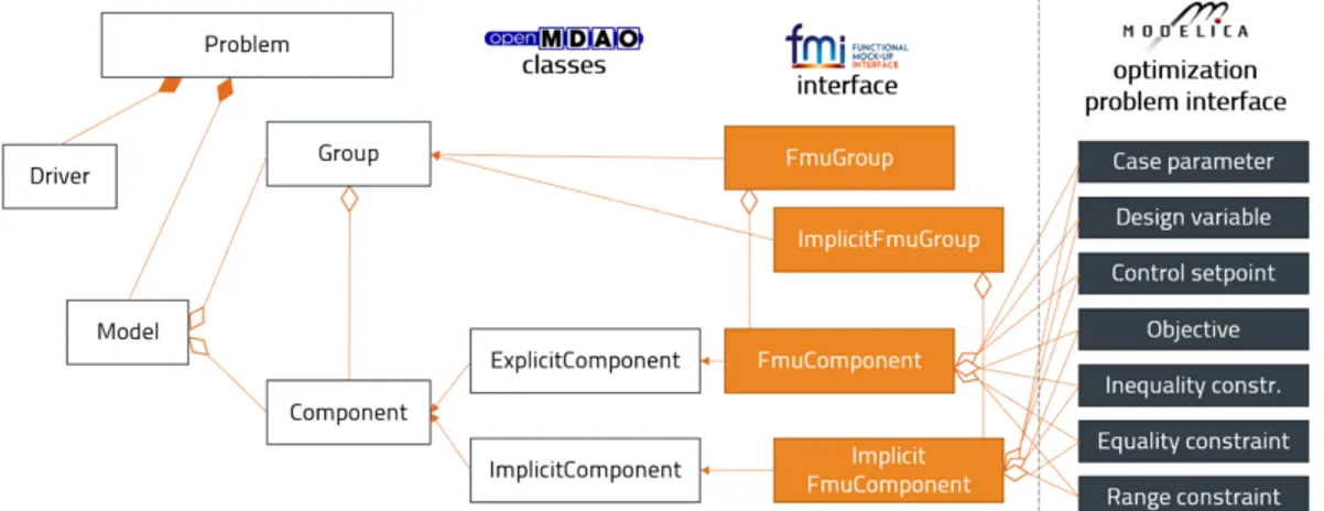
Figure 5: UML-diagram showing how the Modelica models are connected to OpenMDAO via the Functional Mock-up Interface.
In order to efficiently utilize the gradient based optimization methods of OpenMDAO, analytical derivatives can be generated for the Modelica models at compilation. This is a functionality available both in the Optimica Compiler Toolkit [78] and in Dymola [79]. These derivatives are then utilized in OpenMDAO to compute total derivatives for the complete integrated system. If no analytical derivatives have been generated at compilation, the FMUComponent instead utilizes PyFMI to compute the derivatives based on finite differences.
Since the optimization problems consider the aircraft conditions at multiple operating points, a separate class FmuGroup has been created to simulate a certain model for multiple operating points. The above-mentioned naming convention includes features for defining case parameters and control setpoints – parameters and design variables differing between the operating points. The relationship between the Modelica constructs, the FMI related Python classes and OpenMDAO is summarized in the UML-diagram of Figure 5. INTEGRATION EXAMPLE – A PARALLEL HYBRID
This section presents an example use case for the framework detailed in this paper. A parallel hybrid configuration was established within the framework, utilising the models and integration technique described earlier, is presented here. A two and a half shaft GTF, as used for basic A320-200 type aircraft, was selected as the propulsion base. The parallel hybridization was achieved assuming a coupling of an accessory gearbox to the low speed shaft at one end and electrical motor on the other end, in a similar way as the mechanical design for power off-take in a conventional engine, as shown in Figure 6. Design ratings of the engine are listed in Table 1. The airframe considered is a typical tube and wing configuration with a capacity of 150 passengers. General aircraft and mission data are given in Table 2. After designing the aircraft with design range, a typical short-range business case mission was used for block fuel computation.
Model interfaces
Interfaces between the models must be specified in advance for the selected parallel hybrid configuration as shown in Figure 7. Among them, the interfaces between the onboard subsystems are mainly performance data of each subsystems. In this case, the hybridization degree is firstly determined in the gas turbine model for the hybridized gas turbine performance calculation. The power needed from the electrical machine, including the losses of the power transmission, is then transferred to the electrical machine model together with the shaft rotational speed after the gearbox. The speed ratio of the gearbox is fixed within the current framework. The selection of the speed ratio was chosen based on two main factors. Firstly, in order to keep the electrical machine shaft speed between 5000 and 18000 rpm for most of the mission operation. Second, taking the turbomachinery design of the gas turbine into consideration, a typical value for the low-pressure shaft speed of a GTF is about 10000 rpm at the aerodynamic design point. Therefore a speed ratio of 1.5 was selected.
Figure 6 Schematic plot of the parallel hybrid propulsion system Take-off TOC Cruise Thrust [kN] 92.5 24.0 18.0 Altitude [m] 0 10668 10668
Mach [-] 0.25 0.78 0.78
DTisa [K] +15 +10 +0
Table 1 Engine design ratings
Aircraft and Mission Unit Value
Design Range km 4800
Business Case Range km 925 Passenger capability - 150 Wing area m2 122.4 Wing span m 33.91 Tailplane area m2 31.0 Tailplane span m 12.45 Fin area m2 21.5 Fin span m 6.26 Cruise Mach - 0.78
Table 2 Aircraft and mission characteristics
Within the electrical power system, power level, voltage level and the electrical frequency are exchanged including the losses occurred, at the same time sizing the key electrical components. As detailed above, the Battery model also requires the durations of the mission phases from the Mission model for its weight and size calculation.
As described in the modelling sections, thermal management is crucially important for the performance and life of the electrical power system components. As a conventional turbofan air cooled oil cooler is utilised, the Thermal model receives coolant flow properties from the Gas Turbine model and then calculates the oil temperature increase through the hot components. As a serial loop was adopted for the parallel hybrid configuration, an order of cooling was determined based on the criticality and likely physical locations on the aircraft. The battery is cooled first, then the power electronics and the electrical machine. Gas turbine related components are cooled in the latter part of the loop (accessory gearbox, main gearbox, bearings).
With the interfaces of the onboard systems established, uninstalled performance and mechanical design can be determined. The weight and sizing characteristics of the onboard components are then sent to the aircraft structural model. Weight estimation and related changes in the maximum take-off weight
and maximum landing weight are then concluded and the aircraft is ready to fly.
Figure 7 Model interfaces schematic illustration
Regarding the interfaces to the mission model, for the parallel configuration presented, only the performance data from the gas turbine model and the weight information from the aircraft model are needed. As no electrical motor driven propulsor exists, the propulsion force is obtained from the gas turbine only. However, cyclic connections were formed in the setup as the Battery model requires the mission durations from the Mission model, while the Mission model needs the aircraft weight, including the battery mass, for fuel consumption calculation.
Key parameters – design variables and constraints
Key parameters, such as the design variables and constraints, are summarised in Table 3 and Table 4. The hybridization power at different operational points and overall mission profiles are the key factors to be evaluated for the hybrid configuration detailed above. Indeed, the hybridization power, or degree of hybridization, is an inherent design variable for all the models, but the influence of this design variable within the framework begins from the gas turbine model and is transferred to the other subsystems with transfer efficiencies included.
Design variable Model
BPR Gas turbine
FPR Gas turbine
IPC PR Gas turbine
HPC PR Gas turbine
T4 Gas turbine
Hybridization power at different operations Gas turbine /All
Coolant mass flow Thermal
Cooler dimensions Thermal
Table 3 Key design variables considered for the parallel hybrid configuration setup
Constraints defined in the setup are mainly the temperature constraints for the critical components in the subsystems. Ground clearance takes into consideration engine installation limit. Customer requirements, such as take-off distance, plays a very important role in determining a fuel optimal propulsion system design.
Constraint Model
Turbine metal temperature Gas turbine
Ground clearance Gas turbine
Max temperature of conductors Electrical machine Max temperature of end-windings Electrical machine Max temperature of semiconductor
modueles Power electronics converter
Max temperature of core battery
modules Battery
Min temperature of core battery modules
Battery Max temperature of coolant Thermal Max take-off field length Mission
Table 4 Constraints considered for the parallel hybrid configuration setup
Results and discussions
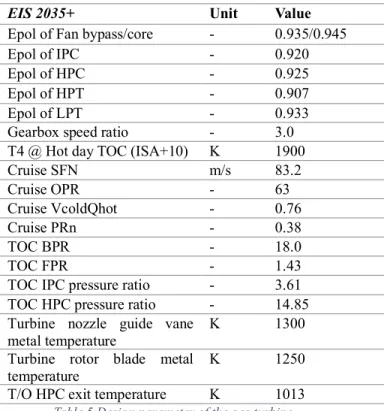
EIS 2035+ Unit Value Epol of Fan bypass/core - 0.935/0.945
Epol of IPC - 0.920
Epol of HPC - 0.925
Epol of HPT - 0.907
Epol of LPT - 0.933
Gearbox speed ratio - 3.0
T4 @ Hot day TOC (ISA+10) K 1900
Cruise SFN m/s 83.2 Cruise OPR - 63 Cruise VcoldQhot - 0.76 Cruise PRn - 0.38 TOC BPR - 18.0 TOC FPR - 1.43
TOC IPC pressure ratio - 3.61
TOC HPC pressure ratio - 14.85
Turbine nozzle guide vane
metal temperature K 1300
Turbine rotor blade metal
temperature K 1250
T/O HPC exit temperature K 1013
Table 5 Design parameter of the gas turbine
The results presented below were produced for a hybridization case where the gas turbine take-off operation is boosted with different level of electrical power. In addition, the added weight of the electrical power system, in which the battery accounts for more than 90% of the total weight, has been reported by many other studies as the major obstacle to the
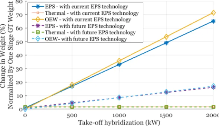
success of hybrid aircraft. Given that, the specific energy and specific power of the battery were manually increased considering possible future technology. The simulations performed with current EPS technology utilised a battery specific energy/power of 0.3 kWh/kg and 0.9 kW/kg respectively, while a future EPS technology assumed 1.5 kWh/kg and 4.5 kW/kg. The turbomachinery efficiencies assumptions and design parameters of the gas turbine are summarized in Table 5. As hybrid propulsion for large aircraft may be expected in a short to medium time frame, a turbofan with expected technology of around 2035 was used to establish a baseline. This engine was selected based on a preliminary single parameter study of the four performance parameters described in the gas turbine section, SFN, OPR, VcoldQhot and PRn. Resulted weight increases of gas turbine, electrical power system, thermal system and aircraft structure for different hybridization with this gas turbine are given in Figure 8. Fuel burn change for the pre-defined business case mission is shown in Figure 9.
Figure 8 Weight change in onboard subsystems and aircraft structure The results above show that with current EPS technology, as is already known, fuel burn penalty is expected. Up to a 62% increase in the propulsion system weight is obtained. Furthermore, additional weight increase due to the stronger aircraft structure pushes the number even higher, 71% of the original propulsion system. Looking into the future, five times higher specific energy/power gives a neutral effect in block fuel, while the added weight of the EPS drops significantly as well as the resulted aircraft structural change. However, even if a five times increase is considered, and it is assumed that the aircraft has a fully charged battery before the flight mission, total energy consumption increase is still observed. Therefore, for this configuration, significant improvements in future EPS technology can only lead to an exchange in the use of electrical energy rather than a small part of the jet fuel. However it is a realistic hypothesis that the gas turbine performance could be improved through hybridization. Indeed, opportunities may arise through re-optimizing the gas turbine within hybrid configurations. As mentioned earlier, Lents C. et al. [22] in their parallel hybrid engine conceptual design reported a modest cruise SFC benefit by downsizing the engine core through hybridization at take-off. This would benefit from achieving a
higher BPR with a constant FPR design. Within the presented framework, the authors have also realized the potential of re-designing the turbine cooling system of the gas turbine through take-off hybridization. As the turbine inlet temperature is actually lower with electrical power boost at take-off, less cooling flow is needed. Similar cruise SFC reduction can be expected from downsizing the core [22]. However, details of gas turbine re-optimization are out of the scope of this paper.
Figure 9 Fuel burn change for the business case mission
Considering the possible cruise SFC benefit by re-optimizing the gas turbine, about 2% cruise SFC reduction with 2MW hybridization at take-off can be achieved, hence the fuel burn penalty can be eliminated with current EPS technology. A fuel burn reduction of 3% may be achieved with the future EPS technology using a snowball effect factor of 1.5 for short range mission. However, as mentioned earlier, taking the electrical energy consumed into account, no benefit in energy consumption would be expected considering all the assumptions made in this paper.
CONCLUSIONS
In this paper, a joint effort by the authors in developing a framework for hybrid aircraft design, optimization and analysis is presented. With physical based models for the key on-board sub-systems and the aircraft structure, trade-offs between performance and sizing characteristics of different design alternatives of these sub-systems can be evaluated. More importantly, through a common API and design platform, mature design tools from each discipline are assembled to achieve a global view of each concept. Full design space exploration of various hybrid concepts is hence available including key design considerations of all the sub-systems.
An integration example of parallel hybrid configuration assessment shows no benefit could be achieved for the configuration. Even with an optimistic assumption in future EPS technology, the improvement is still not fruitful. However, the example itself is showing the most important potential of the framework:
• The described procedure of setting up the parallel hybrid configuration can be used to form various other hybrid concepts.
• For any specific configuration established, resulted interactions and trade-offs of enabling one future technology within one model can be directly observed. • Additional subsystem can be added if necessary. Next step within the framework includes detailed analysis of the presented parallel hybridization and pure serial hybridization separately. Through sensitivity studies of the key design parameters and technology target parameters of each subsystem, the aim is to establish deep understanding of these two basic hybrid configurations. For the gas turbine, typical technology target parameters are the efficiencies of the turbomachines, combustor loss, bypass duct loss, nozzle loss and blade metal temperature limit, and typical design parameters are overall pressure ratio, specific thrust, jet velocity ratio, combustor outlet temperature and pressure ratio split exponent. For the electrical power system, typical technology target parameters are specific power and specific energy, while typical design parameters are electrical power level, motor speed,
voltage level and state of charge of the battery. For the thermal management system, typical technology target parameters include specific weight and effectiveness, and typical design parameters are coolant flow mass flow and temperatures. For the aircraft structures, as any alternative design of the other sub-systems may cause a variation, mainly the technology target parameters related to the other three sub-systems are considered, such as landing gear and airframe related factors.
In terms of future work, more complex hybrid systems will be studied together with unconventional aircraft design. For example, a parallel hybrid architecture with electrically driven fans at the wingtip, will be investigated.
ACKNOWLEDGMENTS
This project has received funding from the Clean Sky 2 Joint Undertaking under the European Union’s Horizon 2020 research and innovation programme under grant agreement number 755458.
REFERENCES
1. Kallas, S. and M. Geoghegan-Quiin, Flightpath 2050: Europe’s Vision for Aviation: Report of the High Level Group on Aviation Research. 2011, European Union. 2. Advisory Council for Aviation Research and Innovation
in Europe, Strategic Research & Innovation Agenda. 2017 Update | Volume 1.
3. Torenbeek, E., Innovative configurations and advanced concepts for future civil aircraft: June 6-10, 2005. 2005: Von Karman Institute for Fluid Dynamics. 4. International Air Transport Association, IATA
Technology Roadmap. 2013.
5. International Air Transport Association, Fact Sheet Technology Roadmap for Environmental Improvement. 2018.
6. Jansen, R., et al. Overview of NASA Electrified Aircraft Propulsion (EAP) Research for Large Subsonic Transports. in 53rd AIAA/SAE/ASEE Joint Propulsion Conference. 2017.
7. Isikveren, A.T., et al., Optimization of Commercial Aircraft Using Battery-Based Voltaic-Joule/Brayton Propulsion. Journal of Aircraft, 2016: p. 246-261. 8. Stückl, S., J. van Toor, and H. Lobentanzer. VOLTAIR–
the all electric propulsion concept platform–a vision for atmospheric friendly flight. in 28th International Congress of the Aeronautical Sciences (ICAS). 2012. 9. Bradley, M.K. and C.K. Droney, Subsonic ultra green
aircraft research: phase I final report. 2011: National Aeronautics and Space Administration, Langley Research Center.
10. Bradley, M.K. and C.K. Droney, Subsonic Ultra Green Aircraft Research: Phase 2. Volume 2; Hybrid Electric Design Exploration. 2015.
11. Bradley, M. and C. Droney, Subsonic ultra green aircraft research phase II: n+ 4 advanced concept development. NASA. 2012, CR-2012-217556.
12. Seitz, A., Advanced methods for propulsion system integration in aircraft conceptual design. PhD dissertation, Technische Universität München, 2012. 13. Seitz, A., A.T. Isikveren, and M. Hornung, Pre-concept
performance investigation of electrically powered aero-propulsion systems, in 49th AIAA/ASME/SAE/ASEE Joint PropulsionConference. 2013. p. 3608.
14. Seitz, A., et al., Electrically powered propulsion: comparison and contrast to gas turbines. 2012: Deutsche Gesellschaft für Luft-und Raumfahrt-Lilienthal-Oberth eV.
15. Isikveren, A.T., et al. Conceptual studies of universally-electric systems architectures suitable for transport aircraft. in Deutscher Luft-und Raumfahrt Kongress. 2012. DLRK Berlin.
16. Isikveren, A.T., et al., Pre-design strategies and sizing techniques for dual-energy aircraft. Aircraft Engineering and Aerospace Technology: An International Journal, 2014. 86(6): p. 525-542.
17. Isikveren, A.T., et al., Conceptual studies of future hybrid-electric regional aircraft. 2015, 22nd International Symposium on Air Breathing Engines: Phoenix, Arizona.
18. Pornet, C., et al., Methodology for sizing and performance assessment of hybrid energy aircraft. Journal of Aircraft, 2014. 52(1): p. 341-352.
19. Pornet, C. and A. Isikveren, Conceptual design of hybrid-electric transport aircraft. Progress in Aerospace Sciences, 2015. 79: p. 114-135.
20. Pornet, C., S. Kaiser, and C. Gologan, Cost-based flight technique optimization for hybrid energy aircraft.
Aircraft Engineering and Aerospace Technology: An International Journal, 2014. 86(6): p. 591-598.
21. Pornet, C., et al., Integrated fuel-battery hybrid for a narrow-body sized transport aircraft. Aircraft Engineering and Aerospace Technology: An International Journal, 2014. 86(6): p. 568-574.
22. Lents, C.E., et al., Parallel Hybrid Gas-Electric Geared Turbofan Engine Conceptual Design and Benefits Analysis, in 52nd AIAA/SAE/ASEE Joint Propulsion Conference. 2016, American Institute of Aeronautics and Astronautics.
23. Strack, M., et al. Conceptual Design Assessment of Advanced Hybrid Electric Turboprop Aircraft Configurations. in 17th AIAA Aviation Technology, Integration, and Operations Conference. 2017. 24. Dean, T., G.E. Wroblewski, and P.J. Ansell. Mission
Analysis and Component-Level Sensitivity Study of Hybrid-Electric General Aviation Propulsion Systems. in 2018 AIAA Aerospace Sciences Meeting. 2018. 25. Raffaelli, L., J.-H. Chung, and I. Popovic, Optimisation
Of A High Bypass Ratio Turbofan Engine Using Energy Storage. Greener Aviation, 2016.
26. Dever, T.P., et al., Assessment of technologies for noncryogenic hybrid electric propulsion. NASA, 2015.
TP-2015-216588.
27. Duffy, K.P. Electric Motors for Non-Cryogenic Hybrid Electric Propulsion. in 51st AIAA/SAE/ASEE Joint Propulsion Conference. 2015.
28. Brown, G.V., et al., NASA Glenn Research Center Program in high power density motors for aeropropulsion. 2005, US Army Research Laboratory Aberdeen Proving Ground United States.
29. Brombach, J., et al. Comparison of different electrical HVDC-architectures for aircraft application. in Electrical Systems for Aircraft, Railway and Ship Propulsion (ESARS), 2012. 2012. IEEE.
30. Kyprianidis, K.G. and A.M. Rolt. On the optimisation of a geared fan intercooled core engine design. in ASME Turbo Expo 2014: Turbine Technical Conference and Exposition. 2014. American Society of Mechanical Engineers.
31. Kyprianidis, K.G., A.M. Rolt, and T. Grönstedt, Multidisciplinary analysis of a geared fan intercooled core aero-engine. Journal of Engineering for Gas Turbines and Power, 2014. 136(1): p. 011203.
32. Walsh, P.P. and P. Fletcher, Gas turbine performance. 2004: John Wiley & Sons.
33. Guha, A., Optimum fan pressure ratio for bypass engines with separate or mixed exhaust streams. Journal of Propulsion and Power, 2001. 17(5): p. 1117-1122.
34. Kyprianidis, K.G., Multi-disciplinary conceptual design of future jet engine systems. PhD dissertation, Cranfield University, 2010.
35. Kyprianidis, K.G., An Approach To Multi-Disciplinary Aero Engine Conceptual Design, in 23rd International
Society for Air Breathing Engines 2017: Manchester, UK.
36. Kyprianidis, K.G., et al., EVA: A Tool for EnVironmental Assessment of Novel Propulsion Cycles. ASME. Turbo Expo: Power for Land, Sea, and Air, Volume 2: Controls, Diagnostics and Instrumentation; Cycle Innovations; Electric Power 2008(43123): p. 547-556.
37. Xu, L., K.G. Kyprianidis, and T.U.J. Grönstedt, Optimization Study of an Intercooled Recuperated Aero-Engine. Journal of Propulsion and Power, 2013.
29(2): p. 424-432.
38. Kyprianidis, K.G., et al., Assessment of future aero-engine designs with intercooled and intercooled recuperated cores. Journal of Engineering for Gas Turbines and Power, 2011. 133(1): p. 011701.
39. Kyprianidis, K.G. and E. Dahlquist, On the trade-off between aviation NOx and energy efficiency. Applied Energy, 2017. 185: p. 1506-1516.
40. MacMillan, W.L., Development of a modular type computer program for the calculation of gas turbine off design performance. PhD dissertation, Cranfield University, 1974.
41. Fawke, A.J. and H.I.H. Saravanamuttoo, Digital Computer Methods for Prediction of Gas Turbine Dynamic Response. SAE Transactions, 1971. 80: p. 1805-1813.
42. Kurzke, J., Achieving maximum thermal efficiency with the simple gas turbine cycle, in 9th CEAS European Propulsion Forum: Virtual Engine-A Challenge for Integrated Computer Modelling, . 2003: Rome, Italy. 43. Saravanamuttoo, H.I.H., et al., Gas turbine theory. 6th
ed. 2009, Harlow, England ; New York: Prentice Hall. 44. Grieb, H., Projektierung von Turboflugtriebwerken.
Technik der Turboflugtriebwerke. 2004, Basel: Birkhäuser Verlag. 826 S.
45. International Aero Engines (IAE), L., Type Certificate Data Sheets and Specifications for PW1100G-JM Series Engines. 2018: United States. Federal Aviation Administration.
46. Lolis, P., Development of a preliminary weight estimation method for advanced turbofan engines. PhD dissertation, Cranfield University, 2014.
47. Greitzer, E.M., et al., N+ 3 Aircraft Concept Designs and Trade Studies, Volume 2, Design Methodologies for Aerodynamics, Structures, Weight, and Thermodynamic Cycles. 2010.
48. Golovanov, D., et al., Multidomain Optimization of High-Power-Density PM Electrical Machines for System Architecture Selection. IEEE Transactions on Industrial Electronics, 2018. 65(7): p. 5302-5312. 49. Dwari, S. and L. Parsa, Design of Halbach-array-based
permanent-magnet motors with high acceleration. IEEE Transactions on industrial electronics, 2011. 58(9): p. 3768-3775.
50. Xu, Z., et al. Mechanical and thermal design of an aeroengine starter/generator. in Electric Machines & Drives Conference (IEMDC), 2015 IEEE International. 2015. IEEE.
51. Pyrhonen, J., T. Jokinen, and V. Hrabovcova, Design of rotating electrical machines. 2013: John Wiley & Sons. 52. Vratny, P., H. Kuhn, and M. Hornung, Influences of Voltage Variations on Electric Power Architectures for Hybrid Energy Aircraft. 2015.
53. Jones, E.C., et al., Comparison of candidate architectures for future distributed propulsion electric aircraft. Vol. 26. 2016. 1-1.
54. Gammeter, C., F. Krismer, and J. Kolar, Weight and efficiency analysis of switched circuit topologies for modular power electronics in MEA. 2016. 3640-3647. 55. Hoelzen, J., et al., Conceptual design of operation
strategies for hybrid electric aircraft. Energies, 2018.
11(1): p. 217.
56. Anseán González, D., et al. Evaluation of LiFePO4 batteries for Electric Vehicle applications. in Conference and Exhibition-2013 International Conference on New Concepts in Smart Cities: Fostering Public and Private Alliances, SmartMILE 2013. 2013.
57. Nagata, H. and Y. Chikusa, All-Solid-State Lithium-Sulfur Battery with High Energy and Power Densities at the Cell Level. Energy Technology, 2016. 4: p. 484-489.
58. Pesaran, A. and M. Keyser, Thermal characteristics of selected EV and HEV batteries, in Proceedings of the Annual Battery Conference: Advances and Applications. 2001: Long Beach, CA. p. 219-225. 59. Abritta, M.V., J. Thorbeck, and B.S. de Mattos, Study of
a Lower-deck Galley for Airliners. Journal of Aerospace Technology and Management, 2012. 4: p. 81-94.
60. Agency, E.A.S., Certification Specifications and Acceptable Means of Compliance for Large Aeroplanes CS-25. 2017, European Aviation Safety Agency. 61. Elham, A., G. La Rocca, and M.J.L.M. van Tooren,
Development and implementation of an advanced, design-sensitive method for wing weight estimation. Aerospace Science and Technology, 2013. 29(1): p. 100-113.
62. Dababneh, O. and T. Kipouros, A review of aircraft wing mass estimation methods. Aerospace Science and Technology, 2018. 72: p. 256-266.
63. Raymer, D., Aircraft Design: A Conceptual Approach, Fifth Edition. 2012, Washington, DC: American Institute of Aeronautics and Astronautics, Inc.
64. Torenbeek, E., Synthesis of Subsonic Airplane Design. 1982, Dordrecht: Springer Netherlands.
65. Nagel, B., et al., Communication in Aircraft Design: Can We Establish a Common Language? 28th International Congress of the Aeronautical Sciences, 2012: p. 1-13.
66. Bachmann, A., et al. A Dynamic Data Integration Approach to Build Scientific Workflow Systems. in 2009 Workshops at the Grid and Pervasive Computing Conference. 2009. IEEE.
67. Federal Aviation Administration, TYPE CERTIFICATION DATA SHEET A28NM. 2007. 68. Jenkinson, L.R., et al., Civil jet aircraft design. Vol.
338. 1999: Arnold London.
69. ESDU, Estimation of airframe drag by summation of components—principles and examples. Engineering Sciences Data Unit, IHS Group, London, UK 1997. Standard NO. ESDU-97016.
70. Laskaridis, P., Performance investigations and systems architectures for the more electric aircraft. PhD dissertation, Cranfield University, 2004.
71. Hwang, J.T., A Modular Approach to Large-Scale Design Optimization of Aerospace Systems. 2015, University of Michigan: Ann Arbor.
72. in OpenMDAO. 2018.
73. Gray, J.S., et al. Automatic evaluation of multidisciplinary derivatives using a graph-based problem formulation in OpenMDAO. in 15th AIAA/ISSMO Multidisciplinary Analysis and Optimization Conference. 2014.
74. FMI Standard. https://fmi-standard.org/, 2018.
75. Andersson, C. and J.a.F. Åkesson, Claus, PyFMI: A Python Package for Simulation of Coupled Dynamic Models with the Functional Mock-up Interface. Technical Report in Mathematical Sciences, 2016: p. 40 pages.
76. in PyFMI. 2018.
77. Rabbat, N.B.G.a.S.-V., Alberto L., A Multilevel Newton Algorithm with Macromodeling and Latency for the Analysis of Large-Scale Nonlinear Circuits in the Time Domain. IEEE Transactions on Circuits and Systems, 1979. CAS-26(9): p. 733-741.
78. Modelon, Optimica Compiler Toolkit, in Modelon. 2018.
79. Dymola web page. 2018.
![Figure 1 Schematic CO2 emissions reduction roadmap [4]](https://thumb-eu.123doks.com/thumbv2/5dokorg/4928401.135651/3.918.111.812.115.500/figure-schematic-co-emissions-reduction-roadmap.webp)