Applying Model Checking for Verifying
the Functional Requirements of a Scania’s
Vehicle Control System
Master Thesis - GSEEM (Global Software Engineering European Master)
School of Innovation, Design and Engineering Mälardalen University Västerås,
Sweden
September, 2012
Shahid Ali
asd11006@student.mdh.se
Muhammad Sulyman
msn11013@student.mdh.se
Supervisors at Scania
Mattias Nyberg
mattias.nyberg@scania.com
Jonas Westman
jowestm@kth.se
Supervisor at University of L’Aquila
Giuseppe Dellapenna
giuseppe.dellapenna@univaq.it
Supervisor at Mälardalen University
Guillermo Rodríguez-Navas González
guillermo.rodriguez-navas@mdh.se
Examiner at Mälardalen University
Paul Pettersson
paul.pettersson@mdh.se
University of L’Aquila,i The authors of this master thesis desire to acknowledge the contribution of their supervisors from Scania and Mälardalen University (MDH) for their continuous guideline and support throughout the whole thesis process. Mattias Nyberg and Jonas Westman as supervisors from Scania facilitated the gathering information about Scania’s vehicle control system used in this thesis work as case study, defining the scope of this master thesis, continuously checking the status of work to keep it according to schedule, provided guidance to make this work a success and helped making critical decisions during this work. Guillermo Rodríguez-Navas González as supervisor from MDH who helped in resolving both technical and administrative issue during this master thesis project and guided us to make this work according to MDH standards. Paul Pettersson as examiner from MDH finally approved this work, his contributions in this field and his published state of the art material in the literature truly helped us a lot throughout the entire thesis work. Gratitude to Mr. Jon Andersson for his help with managerial issues during our stay at Scania. Thanks to Giuseppe Dellapenna for the guidance to make this work approved in University of L’Aquila, Italy.
ii Model-based development is one of the most significant areas in recent research and development activities in the field of automotive industry. As the field of software engineering is evolving, model based development is gaining more and more importance in academia and industry. Therefore, it is desirable to have techniques that are able to identify anomalies in the system models during analysis and design phase instead of identifying them in development phase where it is difficult to locate them and requires a lot of time, effort and resources to fix them. Model checking is a formal verification technique that facilitates to identify the defects in system model at the early stages of system development. There are a lot of tools in academia and industry that provide the automated support for model checking.
In this master thesis one of Scania’s vehicle control system called Fuel Level Display System is modeled in two different model checking tools Simulink Design Verifier and UPPAAL. The requirements that are to be satisfied by the system model are verified in both tools. After verifying the requirements upon system model and checking the model against general design errors, it is established that the model checking can be effectively used for detecting the design errors in early development phases and can help developing better systems. Both the tools are analyzed depending upon the features supported. Moreover, relevance of model checking is studied with respect to ISO 26262 standard.
iii Preface/Acknowledgements...i Abstract ... ii 1. Introduction ... 1 1.1. Background ... 1 1.2. Problem Statement ... 1 1.3. Goals ... 1
1.4. About Scania Group... 2
2. Model Checking... 2
2.1. The Model-Checking Process... 3
2.2. Types of model checkers ... 4
2.3. Model checking in System Development Lifecycle... 4
2.4. Model checking in the fuel level display system ... 5
3. Systematic Literature Review: ... 6
3.1. Inclusion Exclusion Criteria ... 7
3.2. Model Checking Tools... 7
3.3. Why Simulink Design Verifier and UPPAAL?...12
4. Simulink Design Verifier ...13
4.1. Error Detection Using Formal Methods ...14
4.1.1. Detecting Integer Overflow and Division by Zero ...14
4.1.2. Detecting Dead Logic ...14
4.1.3. Detecting Assertion Violations ...14
4.2. Verification of designs against requirements ...15
5. UPPAAL ...17
6. Fuel Level Display System ...18
6.1. Background ...18
6.2. Purpose ...18
6.3. User interaction ...18
6.4. Configuration Parameters ...19
6.5. System Architecture ...19
6.6. Allocation Element Requirements ...21
7. Simulink Design Verifier - Verification Model and Results ...23
7.1. Model of Fuel Level Display system in Simulink ...24
7.2. Input Assumptions ...30
7.3. Activation buttons ...35
iv
7.6. General Design error detection ...51
8. UPPAAL Model and Verification Results ...55
8.1. UPPAAL – Requirements Verification ...64
9. Results...66
9.1. Requirements Verification Results of Simulink Design Verifier ...66
9.2. Requirements Verification Results of UPPAAL ...67
10. Analysis of Model checking tools ...68
10.1. Simulink Design Verifier ...68
10.2. UPPAAL ...69
10.3. Tools Comparison ...70
11. Relevance of Model checking with respect to ISO26262 ...71
12. Conclusion ...74
13. Future work...75
References ...76
v
Figure 1: Model checking architecture. 3
Figure 2: Model checking in classical waterfall model 4
Figure 3: Model checking in case of fuel level display system. 5
Figure 4: Simulink Design Verifier. 13
Figure 5: Architecture for property verification in Simulink Design Verifier. 16
Figure 6: Fuel level display system - components involved. 19
Figure 7: Fuel level display system - information flow. 20
Figure 8: Simulink Design Verifier - verification model. 23
Figure 9: Fuel level display system. 25
Figure 10: Fuel level display system algorithm. 25
Figure 11: Fuel level display system algorithm. 26
Figure 12: Evaluate parking brake. 26
Figure 13: Evaluate parking brake applied. 27
Figure 14: Fuel level estimation algorithm. 27
Figure 15: Algorithm reset calculation. 28
Figure 16: Refuel detection. 28
Figure 17: Refuel detection. 29
Figure 18: Input assumptions. 30
Figure 19: Input assumptions. 31
Figure 20: Params assumptions. 31
Figure 21: Signal assumptions. 32
Figure 22: Verification selectors. 32
Figure 23: Refill scenario. 33
Figure 24: Refill scenario generator. 33
Figure 25: AER202_3 scenario. 34
Figure 26: AER202_3 scenario generator. 34
Figure 27: Verification buttons. 35
Figure 28: AER-01 (AER201_11). 38
Figure 29: Property verification - AER-01 (AER201_11). 38
Figure 30: Property verification - Kalman filter. 39
Figure 31: AER-02 (AER201_12). 40
Figure 32: Property verification - AER-02 (AER201_12). 40
Figure 33: AER-03 (AER201_13) and AER-04 (AER201_14). 41
Figure 34: Property Verification - AER-03 (AER201_13) and AER-04 (AER201_14). 41
Figure 35: AER-05 (AER201_15). 42
Figure 36: Property verification - AER-05 (AER201_15). 42
Figure 37: AER-06 (AER202_2). 43
Figure 38: Property verification - AER-06 (AER202_2). 43
Figure 39: AER-07 (AER202_3). 43
Figure 40: Property verification - AER-07 (AER202_3). 44
Figure 41: AER-08 (AER202_5). 44
Figure 42: Property verification - AER-08 (AER202_5). 44
vi
Figure 46: Requirement verification - AER-02 (AER201_12). 47
Figure 47: Property proving result window. 47
Figure 48: Property proving detailed report. 48
Figure 49: Harness model for AER-02 (AER201_12). 49
Figure 50: Input signals for AER-02 (AER201_12). 49
Figure 51: Configuration for Design error detection. 51
Figure 52: System model after design error detection analysis. 52
Figure 53: Results of design error detection. 52
Figure 54: Detailed design error detection analysis report1. 53 Figure 55: Detailed design error detection analysis report2. 54 Figure 56: Fuel level display system - UPPAAL Architecture Design. 55
Figure 57: UPPAAL Model Navigation Tree. 56
Figure 58: Automata for fuel level sensor. 57
Figure 59: Automata for fuel level estimation algorithm. 58
Figure 60: Evaluate parking brake automata. 59
Figure 61: Parking brake automata. 60
Figure 62: Automata for refill detection. 61
vii
Table 1: Initial search results based on two search strings. ... 6
Table 2: Search results against search string "model checker". ... 6
Table 3: Model checking tools and their features. ...12
Table 4: Parameters for fuel level display system. ...19
Table 5: Requirements for fuel level display system. ...22
Table 6: Constants used in Simulink model of fuel level display system. ...24
Table 7: Common code behind for buttons (1-7). ...35
Table 8: Code behind button AER_201_11. ...35
Table 9: Code behind button AER_201_12. ...36
Table 10: Code behind button AER_201_13_14. ...36
Table 11: Code behind button AER_201_15...36
Table 12: Code behind button AER_202_02...37
Table 13: Code behind button AER_202_03...37
Table 14: Code behind button AER_202_05...37
Table 15: Code behind button View Options...37
Table 16: Code behind preProcessing function block. ...39
Table 17: Code behind postProcessing function block. ...40
Table 18: Global declarations for UPPAAL model. ...57
Table 19: Local declarations for fuel level sensor automata. ...58
Table 20: Local declarations for fuel level estimation algorithm automata. ...59
Table 21: Local declarations for refill detection automata. ...61
Table 22: Local declarations for low fuel level warning automata. ...62
Table 23: Template instantiations. ...63
Table 24: Queries supported by UPPAAL verifier. ...64
Table 25: Requirements Verification Results of Simulink Design Verifier. ...66
Table 26: Requirements Verification Results of UPPAAL. ...67
Table 27: Tools comparison. ...70
Table 28: Classes of severity [4]. ...71
Table 29: Classes of probability of exposure regarding operational situations [4]...71
Table 30: Classes of controllability [4]. ...71
Table 31: ASIL determination [4]. ...72
Table 32: Software architecture design verification methods. ...72
GSEEM (Global Software Engineering European Master) 1
1. Introduction
1.1. BackgroundDue to the increasing complexity in functionality of software applications, the popularity of model-based development has steadily increased over the years and has become a method that is used for both academic and industrial software development purposes. However, verification methods such as manual reviews, walkthroughs or inspections of models are still frequently used in the industry. Manual verification methods are time-consuming and it is very hard to verify that system satisfies all the specifications due to a large network of dependent sub-systems.
Furthermore, with the introduction of new standards, e.g., ISO 26262, requirements engineering has been incorporated into the product development process. Given that a set of requirements has been allocated to a system or sub-systems, the verification of the requirements is necessary. As a natural answer to this, formal model checking has emerged. Formal Model checking aims for automatic verification that a model meets a given set of specifications. There are tools and methods that are currently used for model checking during system development. The aim of this master thesis project is to investigate the possibility of using existing tools and methods for formal model checking in the development of industrial applications.
1.2. Problem Statement
Scania is one of the leading manufacturers of heavy trucks, buses, coaches and engines. A lot of effort, time, money and resources are required to fully test all the vehicle control systems deployed in their products. Scania wants to check if introducing model checking techniques in their systems can improve the quality of current testing process and can it be used as an alternative to testing, which will eventually help them to save some of the resources which are currently being consumed for testing all the vehicle control systems. Furthermore it is also required to investigate the relevance of model checking with respect to the latest ISO 26262 standards, and to analyze different model checking tools based upon their features for model checking.
1.3. Goals
This master thesis project can be divided into following different sub-goals
1. Analyze the academic and industrial world to find initial set of relevant tools/methods for formal model checking.
2. Narrow down the initial set of methods/tools down and finalize two suitable model checking tools for modeling based upon their coverage, manageability, degree of maturity, and applicability.
3. Choose a well-documented, non-trivial best-practice example at Scania to be modeled by using the selected model checking tools. Selection of the vehicle control system is based upon the documentation, test data, requirements and state machines available for the system at Scania. 4. Model the best practice selected vehicle control system in finalized model checking tools and verify the system model against the specified requirements. Also verify the system model against general design errors.
5. Evaluate the results with respect to industrial relevance and usefulness in terms of compliance with ISO 26262. Analyze the model checking tools used during this master thesis project based upon the features offered by the tools.
GSEEM (Global Software Engineering European Master) 2
1.4. About Scania Group
This master thesis is performed at Scania Group situated in Södertälje, Sweden in REPA department. Scania was founded in 1891 and presently is one of the leading manufacturers of heavy trucks, buses, industrial and marine engines. Scania has branches in around 100 countries all over the world. Overall Scania has more or less 37,500 people employed in different departments. Out of 37,500 employees 3,300 are working in research and development department in Södertälje, Sweden [3]. Disclaimer:
All the numerical values mentioned in the requirements of fuel level display system are arbitrary values and do not represent the actual values in Scania fuel level display system.
2. Model Checking
With the evolution of modern technologies dependability of organizations and individuals over software applications is remarkably increased. In many situations these software applications are critical for the safety of individuals and the environment in which they are operating. So it has become a strict requirement that these applications must be fail safe and error free. But due to the complex nature of software, this requirement cannot be achieved 100%. There exist different testing strategies but it is very expensive, time consuming and difficult to make a complete and comprehensive list of testing scripts. To cope with these limitations formal verification technique called model checking can be used. By using formal verification techniques verification activity can be initiated very early in the design process which makes verification activity more effective and less time consuming [1].
Models describing the behavior of the system in a precise and clear manner are used by the model based verification techniques. Correct modeling of the system behavior can discover the inconsistencies in system behavior with respect to its specifications [1].
In model checking all possible systems scenarios and states are explored in a brute force manner just like the chess program that examines all possible moves. By using this way of verification it can be proved that the system truly satisfies certain properties. Certain errors which remain undiscovered during simulation, testing and emulation can be potentially discovered by using model checking. As the name implies, model checking checks the model of the system that is an abstract and high level description of the system, it does not checks the actual program of the system. It is a great challenge for the developers to make a model of the system that truly represents the actual system. The main obstacle in model checking is the abstraction of the software application. It states that during abstracting the real world problem, the important and critical aspects of the system model should not be left out. The abstraction should be comprehensive enough to contain all the critical aspects of the system. Otherwise, the model checker will be useless if it cannot explore the states which could possibly give rise to errors and compromise the safety in some critical software applications [1]. Model checking is a software verification technique that uses model of the software application and tries to verify certain properties on the software model during execution. Precisely it can be said that model checking process is basically composed of designing system model, properties definition, running the model checker and analyzing the results [1].
GSEEM (Global Software Engineering European Master) 3
2.1. The Model-Checking Process
Following are the different phases in model checking process [1] 1) Designing system model:
Model description language provided by the model checking tool under hand is used to model the system under consideration. Designing a system model usually involves making finite state machines which specify desired behavior of the system that can be defined in terms of variables, initial values for the variables, environmental assumptions, and description of conditions under which values of variables will change [1].
2) Properties definition:
Properties of the system to be verified against the system model are defined by using some temporal logic constraints for example linear temporal logic (LTL) or computation tree logic (CTL). Each model checking tool supports different kind of property specification language [1].
3) Running the model checker:
Model checker is executed to check the validity of the defined properties against the system model. Results of the model checker are stored to be analyzed at the later stages [1].
4) Analyzing the results:
Results of the model checker are analyzed. If the current property for which model checker was executed is satisfied by the system model then check the next property if there is any. And if the property is violated by the system model then analyze the counter example or error path generated by the model checker and based upon that refine the system model, design of system or may be the property. Repeat the entire above procedure until all the properties are satisfied by the system model. During model checking lot of states are generated by the model checker so there is a possibility of getting out of memory error. In such case either reduces the system model or use more sophisticated techniques for model checking [1]. Figure 1 presents the overall architecture of model checking.
GSEEM (Global Software Engineering European Master) 4
One problem that is normally faced during model checking is the state space explosion problem. It is a very critical issue to examine the largest possible state spaces that can be handled with available resources (processor and memory). State-of-the-art model checkers can handle 108 to 109 states with explicit state-space enumeration. By employing efficient algorithms and customized data structures 1020 to 10476 states can be handled [1].
2.2. Types of model checkers
Based on the model specification and state space, there exist different types of model checkers. Mainly the model checkers can be divided into two categories
1) Explicit model checkers. 2) Implicit model checkers.
Explicit model checkers construct a searchable representation of the design model and store a representation of each state visited [1]. Implicit model checkers also called symbolic model checkers use logical representations of sets of states (such as binary decision diagrams) to describe the regions of model state space that satisfy the properties being evaluated. Such compact representations generally allow symbolic model checkers to handle a much larger state space than explicit model checkers [1].
Some recently developed model-checkers use satisfiability modulo theories (SMT) solvers for reasoning about infinite state models containing real numbers and unbounded arrays. These model checkers use a form of induction over the state transition relation to automatically prove that a property holds over all executable paths in a model. While these tools can handle a larger class of models, the properties to be checked must be written to support inductive proof [1].
2.3. Model checking in System Development Lifecycle
Following figure 2 represents the timing for conducting model checking activity in classic waterfall model, during system development life cycle. Model checking can be categorized into two categories classic model checking and modern model checking. Classic model checking can be performed during analysis, design or before the coding activity in system development lifecycle. And improvements can be made in the system model based upon the outcomes of model checking. Modern model checking is carried after the coding activity. This can complement the testing activity and improvements can be made in the model depending upon the outcomes of model checking activity [13].
GSEEM (Global Software Engineering European Master) 5
2.4. Model checking in the fuel level display system
In case of Scania’s vehicle control system fuel level display system, this system is already developed, tested and working in their trucks. The main purpose of applying model checking to this vehicle control system is to investigate the validity of the design by using model checking techniques and also to see whether it’s feasible to replace current verification techniques used in Scania with model checking. Or if not completely replacing the current verification style then how model checking can help improving the current verification activity. Because model checking is supposed to complement the testing, it’s not an alternative of testing.
Current verification methods employed in Scania are time-consuming and due to the large network of dependent sub-systems it can be hard to verify that a system meets all the specifications. By using model checking it can be ensured that almost 100% test coverage has been achieved and it can be justified with proof from model checking tools which is hard to perform in case of manual testing techniques.
Since the fuel level display system application is already developed, tested and is working in actual products which mean that the system is in maintenance phase so the model checking activity in this case is after the testing activity during maintenance activity as shown in the following figure 3. But since the company is open to the changes in the design of the system depending upon the out-come of the model checking activity so this model checking activity can also be related to the analysis and design phases and also before the coding phase as described by the classical waterfall software development model of Pressman 1996.
GSEEM (Global Software Engineering European Master) 6
3. Systematic Literature Review:
Systematic literature review for searching the existing model checking tools was initiated on 17 March, 2012. Springerlink, ACM Digital Library and Google Scholar search engines are used to search for the existing model checking tools. Systematic literature review was started with following two search strings.
1. “Model checker”. 2. “Model checking tool”.
Following table 1 shows the results that are obtained on the basis of two search strings. This table differentiates the number of results based upon the title and abstract search, and whole body search.
Search Engine Search String Title and Abstract Whole Paper/body
Springerlink Model Checking Tool 966 46955
Springerlink Model Checker 1159 11297
ACM Digital Library Model Checking Tool Title: 9 Abstract: 396
17,167
ACM Digital Library Model Checker Title: 36 Abstract: 463
5806 Google Scholar Model Checking Tool Title: 133 1220000
Google Scholar Model Checker Title: 631 79200
Table 1: Initial search results based on two search strings.
Based upon the initial research results it was discovered that the first search string “Model Checker” is returning most relevant results as compare to the string “Model checking tool”. Therefore the string “Model Checker” was finalized for this research.
Search Engine Search String Title and Abstract Whole Paper/body
Springerlink Model Checker 1159 11297
ACM Digital Library Model Checker Title: 36 Abstract: 463
5806 Google Scholar Model Checker Title: 631 79200
Table 2: Search results against search string "model checker".
After reading the title, abstracts and introduction 96 papers are considered relevant. Then after reading the whole papers only 37 papers are found relevant, each of them presented at least one model checking tool. Eventually it is discovered according to the systematic literature review that there are 54 model checking tools present with different features and functionality that they support. Therefore these 54 tools are considered the currently existing tools for this systematic literature review about model checkers. Since the main purpose of this master thesis is not to study about the existing model checking tools but to perform model checking upon fuel level display system of Scania, that’s this systematic literature review is kept short and brief.
GSEEM (Global Software Engineering European Master) 7
3.1. Inclusion Exclusion Criteria Inclusion Criteria:
1. All papers that present at least one model checking tool are included. 2. All the papers about model checking tools are included.
3. All papers generally talking about model checking techniques and methodologies are included.
4. All papers about how model checking tools and techniques work are included.
5. Books, thesis, articles, journals, conference proceedings and technical reports related to model checking are included
6. No specific time limit is enforces on the search. All relevant articles until the search date are included.
Exclusion Criteria:
1. All papers which are not in English language are excluded. 2. All papers about how model checking tools are built are excluded. 3.2. Model Checking Tools
Different types of temporal logics are used by the model checking tools to express the properties of system as logical formulas to be verified on the system model. Most of model checking tools use either linear time or branching time logics. Properties that can be expressed in either of these logics they can also be expressed in the other one as well. But some of the tools use different types of logic to formulate the properties.
Linear Time:
[16] Linear time also called linear temporal logic or linear-time temporal logic (LTL) is a modal temporal logic with modalities that refer to time. In LTL formulas future can be encoded. For example a condition will finally be true; a condition will be true until another fact becomes true, etc.
Branch Time:
[16] Branch time also called computation tree logic (CTL) is branching-time logic. Its model of time is a structure like tree where the future is not determined. There are different paths in the future that can be followed; any one of them can be selected as future path. In CTL it can be specified that when an initial condition is true then all possible executions of a program avoid some unwanted state or condition.
Other:
There are model checking tools which use different type of logics to formulate the properties of the system to be verified as mentioned in the table below in the column named as other, next to the column named linear time.
Real Time:
Real time systems are the systems that operate under time sensitive environment and provide guaranteed response within strict time constraints. Real time column shows that the tool supports the modeling, verification and analyses of real time systems.
Probabilistic:
Probability is an important component in the design and analysis of complex systems. Probabilistic model checking is a formal verification technique for modeling and analyzing the systems.
GSEEM (Global Software Engineering European Master) 8
Probabilistic column in the table below shows the tools that support the modeling and analysis of systems that exhibit probabilistic behavior.
Hybrid:
Hybrid column shows that the tools marked as hybrid supports both real time and probabilistic model checking approaches.
GUI:
Graphical user interface (GUI) column shows that which of the tools provide graphical user interface for modeling the system and for formulating the properties of the system to be verified.
Availability:
Availability column shows that under what conditions the tools is available for use. Availability of the model checking tools can be divided into three types
1. Free - Free means that the tools are freely available to be downloaded and to be used for all kinds of users.
2. Free Under condition - Free under condition means that tool is available to be downloaded and used for the academic purposes but if someone wants to use it for the commercial purposes then licenses are required.
3. Commercial - Commercial means that license must be acquired for downloading and using the model checking tool.
GSEEM (Global Software Engineering European Master) 9
Following table presents the model checking tools, and features supported by them, which exist until now in academia and industry [2].
Short Name Full Name Linear
Time
Branch Time
Other Real
Time
Probabilistic Hybrid GUI Availability
Alpina Alpina Reachability Free
APMC Approximate Probabilistic Model Checker
Free Under
Condition
ARC AltaRica Checker Modal mu-calculus Free Under
Condition
Bandera Bandera Free
Blast Berkeley Lazy Abstraction Software verification Tool
Free
Cadence SMV
Cadence SMV Free Under
Condition
Cascade Cascade Abstract syntax tree Free
CADP Construction and Analysis of Distributed Processes
Free Under
Condition CWB - NC The Concurrency Workbench
of New Century
Free Under
Condition
DBRover DBRover Commercial
DiVinE Tool Distributed Verification Environment -- Tool Set
Free
DREAM Distributed Real-time Embedded Analysis Method
Discrete event simulator Free
Edinburgh CWB Edinburgh Concurrency Workbench Free Under Condition
Expander2 Expander2 Free
Fc2Tools Fc2Tools and Autograph Free
GEAR Modal mu-calculus Free Under
Condition
HSolver HSolver Safety Free
GSEEM (Global Software Engineering European Master) 10
IF IF Toolbox Free
INA Integrated Net Analyzer Deadlock-freedom,
Reachability, Coverability, Invariants, Structural Analysis
Free
JPF Java PathFinder Free
KRONOS KRONOS Free
LTSA Labelled Transition System Analyzer
Free
MCRL MCRL toolset Free
mCRL2 mCRL2 toolset Free
Mocha Mocha ATL Free
Moped Moped Free
MRMC Markov Reward Model Checker
Free
mucke mucke Mu-calculus Free Under
Condition NuSMV NuSMV: a new symbolic model
checker
Free
PAT Process Analysis Toolkit Free
PEP PEP - Programming
Environment based on Petri nets
Free
PRISM Probabilistic Symbolic Model Checker
Free
PROD PROD Deadlock-freedom,
Reachability
Free
PVS Prototype Verification System Free Under
Condition Reactis
Tester
Reactis Tester Automatic Test Case
Generation
Commercial
GSEEM (Global Software Engineering European Master) 11
Condition SMCWWI Simple Model Checker With
Web Interface
Free
SPIN Simple Promela Interpreter Free Under
Condition
Statestep Statestep Safety (non-reachability),
explicit completeness
Free Under Condition
STeP Stanford Temporal Prover Free
TAPAAL TAPAAL Free
TAPAs Tool for the Analysis of Process Algebras
Free Under
Condition Temporal
Rover
Temporal Rover Commercial
The Kit The Model-Checking Kit Deadlock-freedom,
Reachability
Free TIMES A Tool for Modeling and
Implementation of Embedded Systems
Free Under
Condition
TRON Uppaal TRON Timed testing using
model-checking techniques
Free Under
Condition
Truth Truth Free
TwoTowers Free Under
Condition
UPPAAL UPPAAL Toolkit Free Under
Condition
VeriSoft VeriSoft Free
VIS Verification Interacting with Synthesis
Free
Ymer Ymer Free Under
Condition
[mc]square [mc]square Free Under
GSEEM (Global Software Engineering European Master) 12
Simulink Design Verifier (Prover)
Simulink Design Verifier (Prover)
SMT – Satisfiability modulo theories
Commercial
CMurphi CMurphi Free
RT-SPIN Real Time - Simple Promela Interpreter
Free Under
Condition Table 3: Model checking tools and their features.
3.3. Why Simulink Design Verifier and UPPAAL?
During this systematic literature review fifty five tools are discovered that can be used for model checking. For this master thesis project Simulink Design Verifier and UPPAAL are selected to perform the activity of model checking on Scania’s vehicle control system.
The main reason for the selection of Simulink Design Verifier is that Scania uses Simulink to build the models of their vehicle control systems. It is desirable, from Scania’s point of view, to determine whether the existing Simulink models of Scania’s vehicle control system can be used in the future for model checking by Simulink Design Verifier or not. Building the system model from scratch in any other model checking tool requires a lot of time and resources and if the existing Simulink models can be used for model checking then a lot of such effort can be saved.
The vehicle control system that is selected for model checking for this master thesis is a real-time system. UPPAAL is a model checking tool particularly suitable for modeling, simulation, validation and verification of real-time systems. It is also one of the most used, updated and continuously evolving tool. Hence, after discussion with supervisors from Scania, UPPAAL is selected as the second tool for model checking during this master thesis project.
GSEEM (Global Software Engineering European Master) 13
4. Simulink Design Verifier
Simulink Design Verifier identifies design errors, generate test vectors, and verify designs against requirements. It uses formal methods to identify hard to find design errors in models without requiring extensive tests or simulation runs. Design errors that can be detected by Simulink Design Verifier include dead logic detection, integer overflow identification, division by zero, and violations of design properties and assertions [8].
Model blocks that contain errors are highlighted in Simulink Design Verifier and it is also possible to highlight the blocks that do not contain any error. Signal range boundaries are calculated and test vectors are generated by Simulink Design Verifier for reproducing the errors later during simulation. Simulink Design Verifier also facilitates to perform analysis of model in simulink environment. Design and requirements can be validated in early phases without generating the code. Verification and validation activities can be conducted in the whole design phase. Model analysis supports simulation and allows the users to use simulation results as inputs to analyze the models by using formal methods. Discrete-time subset of Simulink and State flow are also supported by Simulink Design Verifier. State flow is typically used in embedded control designs [8].
Following are the key features provided by Simulink Design Verifier [8]
Simulink Design Verifier uses Polyspace and Prover Plug-In as formal analysis engines.
Detection of design errors like integer and fixed-point overflows, division by zero, dead logic detection, violations of design properties and assertions violations.
Simulink Design Verifier provides blocks and functions for modeling functional requirements and safety requirements.
Test vector can be generated from functional requirements. Model coverage is ensured by model coverage objectives which include condition, decision, and modified condition/decision coverage (MCDC).
Property satisfaction by identification of failure locations for analysis and debugging.
Simulink Design Verifier also provides model support for fixed-point and floating-point models. Support for floating point really makes a difference as compared to UPPAAL that does not support the floating point models.
GSEEM (Global Software Engineering European Master) 14
Formal analysis techniques manufactured by Prover Technology called Prover Plug-In and Polyspace formal analysis engine created by MathWorks are used by Simulink Design Verifier for formal analysis. Both of these formal analysis techniques depend upon rigorous mathematical procedures for searching the possible execution paths in the model for test cases generation and counter examples generation. In traditional testing methods test scenarios and expected results are presented with concrete data values but it’s not the same in formal analysis techniques. In formal analysis techniques user can work with models of system behavior rather than concrete data values. Models of test scenarios and verification objectives that describe expected and unexpected system behaviors can be included in system behavior models. Formal analysis that is conducted by using such models complements simulation and provides a deeper understanding of system design [8].
4.1. Error Detection Using Formal Methods
Simulink Design Verifier can discover whether certain scenarios can occur under specific conditions or not. This information can be used to improve the design, refine the requirements, guide the simulation for debugging, verification and validation. Simulink Design Verifier supports the detection of design errors like integer overflow, division by zero, dead logic, and assertion violations [10].
4.1.1. Detecting Integer Overflow and Division by Zero
Simulink Design Verifier provides design error-detection mode to discover integer overflow and division by zero errors. This analysis is automatically performed which does not require the user to provide any additional inputs. Permitted ranges for all type of signals on every block are provided to direct the user in identifying the root cause of error. Results can be viewed in the form of model or in an HTML report format after the analysis is finished. Blocks are marked as green, yellow, or red in the model. Blocks marked as green shows the blocks that are proven to be unable to cause any integer overflow or division by zero errors. Blocks are marked with yellow when analysis cannot produce a conclusive result or when the time limit for the analysis is exceeded than expected. When an error is detected in the model execution sequence, all sub-blocks in the path that can cause integer overflow and division by zero are marked with yellow. Blocks marked with red shows the blocks that have integer overflow or divide by zero errors. For the blocks marked with red Simulink Design Verifier generates test cases that can reproduce the problem during simulation or testing. Test case can be invoked and simulation can be executed directly within simulink [10].
4.1.2. Detecting Dead Logic
Test-generation mode in Simulink Design Verifier is used to detect dead logic in model, which identifies the model objects that are either outdated or the model objects that are proven to remain inactive during the execution process. Dead logic can be caused by a design error or a requirement error. When code is generated then, if dead logic is present in the system model it leads to dead code. It is very difficult to detect dead logic by testing only in simulation because even after running many simulations, it can be difficult to state that a specific logic or portion of model remains inactive. At the end of the analysis of test-generation the model is colored according to the test-generation criteria. Portions of model that have dead logic are marked as red and the parts of model that have logic which can be completely activated in simulation are marked as green. Test cases are generated by Simulink Design Verifier to reproduce the dead logic in simulation [10].
4.1.3. Detecting Assertion Violations
To detect assertion violations Simulink Design Verifier provides assertion violation detection setting in property-proving mode. Simulink Design Verifier checks if there is any valid scenario that can
GSEEM (Global Software Engineering European Master) 15
trigger some assertions during simulation by remaining within the number of time steps mentioned in the analysis settings. All the assertions that can be violated by any valid scenario are marked with red. Test vector is generated for the triggered assertion. Some assertions are available in simulink by default and Simulink Design Verifier also provides extra blocks for defining additional constraints for analysis that empower the user to thoroughly analyze design behavior and detect design flaws prior to running the simulation [10].
4.2. Verification of designs against requirements
Functional requirements of systems are traditionally clear statements about expected behaviors of the system. It can also be mentioned in the requirements about the behaviors that a system must never demonstrate. Scenarios that must never be shown by the system are referred to as functional safety requirements [11].
In order to formally check that the system design behaves according to the functional requirements, the requirement statements which are normally written in plain human language are first needed to be translated into the language that is understandable by the formal analysis engine under consideration. Simulink Design Verifier allows the users to state formal functional requirements using simulink blocks, MATLAB functions and Stateflow. Every requirement which is created in simulink for verification has one or more objectives associated with it. These verification objectives are eventually used to investigate if the system design fulfills the functional and safety requirements or not. Simulink Design Verifier provides a block library that includes blocks and functions for defining test objectives, proof objectives, assertions, constraints, and dedicated set of temporal operators for modeling of verification objectives with temporal aspects [11].
Simulink Design Verifier provides two blocks to specify property proofs: 1) Proof Objective 2) Proof Assumption. Proof objective define the values of a signal to be proved and proof assumption ensure constrains on the values of signals during a proof.
Figure 5 describes the property verification architecture that is followed in Simulink Design Verifier for verifying the properties. This property proving architecture is followed for verifying the properties of fuel level display system of Scania during this master thesis project. First of all, inputs to the system are defined and then assumptions sub-model defines the assumptions on the input values. Assumptions defined on inputs in assumptions sub-model are used by both the system model and the verification sub-model. Verification sub-model also uses the output from system model for property proving. Verification sub-model can have multiple objectives associated to it that the system is expected to satisfy.
GSEEM (Global Software Engineering European Master) 16
Figure 5: Architecture for property verification in Simulink Design Verifier.
Once requirements and verification objectives are identified and captured in the verification model they can be used to illustrate the correctness of system design using formal methods. Test Objective blocks and MATLAB functions can be used for defining test objectives. During test generation Simulink Design Verifier will try to find a valid test case that meets the specified test objectives. If there is a situation that certain objective can never be met then the system design cannot perform the desired feature against the specified set of analysis constraints [11].
In order to test the correctness of system design against safety requirements, proof objective blocks and MATLAB functions are used for specifying proof objectives. Simulink Design Verifier examines all possible input conditions that can cause undesired behavior during analysis and then report the results. System design can be proven valid or it can violate the functional safety requirements for a given proof objective. Whenever a violation of proof objective against requirements is detected, test vector is generated by Simulink Design Verifier that can be used later to demonstrate the violation during simulation [11].
Algorithms and logic developed in Simulink and stateflow models to generate test cases and parameters is analyzed by Simulink Design Verifier. This kind of analysis is required by industry for developing systems with high integrity level and to meet the objectives set by the standards. To make sure the structural test coverage criteria for test generation condition, decision and modified condition/decision coverage (MC/DC) techniques are used by Simulink Design Verifier [12].
TÜV SÜD has certified Simulink Design Verifier. Simulink Design Verifier is certified to be used in development process of systems. Processes of system development must comply with ISO 26262, IEC 61508, or EN 50128 standards [12].
GSEEM (Global Software Engineering European Master) 17
5. UPPAAL
UPPAAL is a model checking tool for modeling, simulation, validation and verification of real-time systems that are modeled as networks of timed automata. Finite state machines with time clocks are known as timed automata. UPPAAL does the verification and validation of the modeled systems by using two techniques. 1) constraint-solving 2) on-the-fly techniques. In UPPAAL validation is done by graphical simulation and verification is done by automatic model-checking. In simulation modeled system is executed interactively and is observed that whether the system satisfy the expected behavior or not. UPPAAL uses finite state automata extended with clock and data variables. UPPAAL uses a subset of TCTL (timed computation tree logic) to model the requirements to be verified on the system model. UPPAAL facilitates with the features of counter example generation and counter example visualization [7], [17].
Typical application areas for which UPPAAL is considered best include real-time controllers and communication protocols in particular, those where timing aspects are critical. It is designed mainly to check invariant and reachability properties which are done by exploring the state-space of a system. Two main parts of UPPAAL are graphical user interface and a model checker engine. Graphical user interface is implemented in Java language and is executed on the user end. Model checker engine is developed is C++ and is also executed on the user work station but UPPAAL offers the flexibility of running the engine on a separate machine that is more powerful and can be referred as server. Two main advantages of UPPAAL are efficiency and easy to use. Model checker engine applies on-the-fly searching technique in combination with the symbolic technique which makes the verification problem reduced to the problem of solving simple constraints system [7].
UPPAAL can also generate a problem trace automatically, that can be used to diagnose the problem and can also be used to explain why a property is or is not satisfied by the described system. The traces can be visualized graphically by using the simulator provided by UPPAAL. Three main components of UPPAAL are 1) editor, 2) simulator and 3) verifier. It is freely available for academic purposes and it also has a commercial version available for industrial use which requires purchasing license for commercial use. It is available for Windows, UNIX and related platforms. UPPAAL is a joint venture of Department of Information Technology at Uppsala University, Sweden and Department of Computer Science at Aalborg University, Denmark. Initial version of UPPAAL was released in 1995 since then it has been continuously evolving and updating [17].
GSEEM (Global Software Engineering European Master) 18
6. Fuel Level Display System
This section contains the detailed description for fuel level display system of Scania. Functional requirements that are to be verified on the system model of fuel level display system during model checking activity are described. The overall architecture of the vehicle control system is also explained in this section in detail.
6.1. Background
In the beginning the plan was that different existing vehicle control systems in Scania will be studied and one of them will be selected for model checking based upon its documentation, test data, requirements and state machines available. Later-on the supervisors at Scania proposed to use Fuel Level Display System which is a well-documented and best-practice example at Scania. This system has already been used in different research projects and master thesis as case study.
Basic goal of the fuel level display is to keep the vehicle from running out of fuel. Current fuel level is continuously calculated and displayed to the driver on gauge. Driver may not monitor the fuel level gauge frequently so a warning is useful. A low fuel level warning is introduced to make the driver aware of the fuel level if fuel level in the fuel tank drops below a predefined limit and a refill is needed.
6.2. Purpose
This system intends to show the fuel level for all vehicles independent of vehicle and fuel type. A low fuel level warning is also present on vehicles, indicating if the fuel level is low as compared to a predefined limit.
6.3. User interaction
The fuel level is measured and presented to the driver in the instrument cluster. If the fuel level is below a predetermined level a warning is presented in the instrument cluster. The low fuel level warning could be used on both trucks and buses. Fuel level display system can be divided into following two sub categories
1. Fuel level estimation: It estimates the current fuel level in the fuel tank.
2. Low fuel level warning: it creates a warning if the fuel level in the tank is considered to be low as compared to a predefined value.
There are two documents in Scania listing all the functional requirements related to fuel level estimation and low fuel level warning. AE201 contains the functional requirements for fuel level estimation and AE202 contains the functional requirements for low fuel level warning.
The fuel level sensor comes in different types depending on the fuel tank, fuel injection system and electrical characteristics of the fuel sensor.
Following are the different steps which are performed in fuel level display system 1. Read fuel height
2. Calculate fuel level 3. Send fuel level
4. Detect and display low fuel level 5. Display fuel level
GSEEM (Global Software Engineering European Master) 19
6.4. Configuration Parameters
There are following 4 different types of variants for fuel level display system 1. Truck with fuel engine
2. Bus with fuel engine 3. Bus with gas engine 4. Truck with gas engine
There are multiple types of sensors and multiple sizes of fuel tanks that are used in fuel level display system. Total fuel level can be either calculated by COO (Coordinator) or received from CAN (Controller area network). For the sake of simplicity and clarity in this master thesis only one type of system variant is considered that is truck with fuel engine. One type of sensor and one size of fuel tank is considered and the variant where total fuel level is calculated by COO is used.
Variant 1 Truck with fuel engine
fuelLevelSensorParam 15 (Wema-general : short) fuelTankSizeLeft 13 (450 liter volume: General) fuelTankSizeRight Same as for fuelTankSizeLeft
fuelLevelTotalParam 10 (Total fuel level calculated by COO) Table 4: Parameters for fuel level display system.
6.5. System Architecture
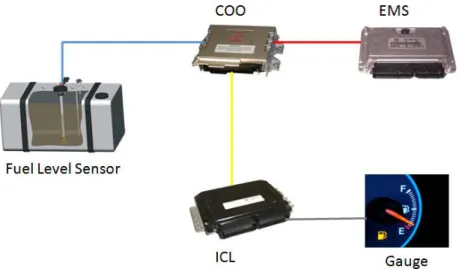
Following figure 6 shows the components at abstract level that are involved in the fuel level display system. Fuel level sensor is mounted inside the fuel tank. ECUs (electronic control units) that are involved in fuel level display system are COO (coordinator), EMS (engine management system) and ICL (instrument cluster). Gauge is not a separate component it is a part of ICL.
Figure 6: Fuel level display system - components involved.
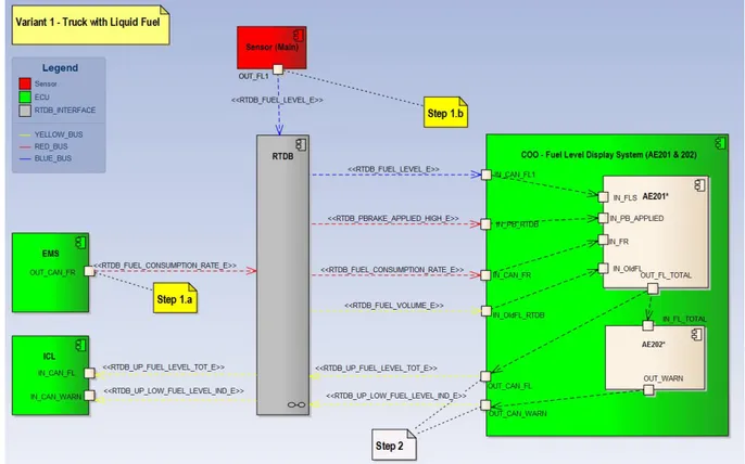
Figure 7 shows the information flow between different components involved in fuel level display system. Fuel Rate (RTDB_FUEL_CONSUMPTION_RATE_E) comes from EMS through red CAN bus to RTDB (real time data base). Value from fuel level sensor (RTDB_FUEL_LEVEL_E) inside the tank comes through blue CAN bus to RTDB. COO uses the values from RTDB through different buses for performing different operations.
COO reads fuel level sensor value (RTDB_FUEL_LEVEL_E) on blue CAN bus, parking brake value (RTDB_PBRAKE_APPLIED_HIGH_E) on red CAN bus, fuel Rate (RTDB_FUEL_CONSUMPTION_RATE_E)
GSEEM (Global Software Engineering European Master) 20
on red CAN bus, old fuel volume (RTDB_FUEL_LEVEL_E) on yellow bus from RTDB. COO places fuel level (RTDB_UP_FUEL_LEVEL_TOT_E) and low fuel level indication (RTDB_UP_LOW_FUEL_LEVEL_IND_E) in RTDB through yellow CAN bus.
ICL uses the fuel level (RTDB_UP_FUEL_LEVEL_TOT_E) and low fuel level indication (RTDB_UP_LOW_FUEL_LEVEL_IND_E) from RTDB through yellow CAN bus to indicate the fuel level and the low fuel level warning respectively.
Figure 7: Fuel level display system - information flow.
Requirements mentioned in document AE201 and AE202 are implemented inside the COO. * With AE201 and AE202 represent that here only subsets of these requirements that are mentioned in the documents are implemented. All the requirements mentioned in table 5 are implemented inside COO. Rests of the requirements are either background requirements or assumptions about the system. Only the requirements that are mention in the table 5 are considered relevant for model checking.
GSEEM (Global Software Engineering European Master) 21
6.6. Allocation Element Requirements
Table 5 contains the functional requirements for fuel level display system of scania that are to be verified on the fuel level display system model in both Simulink Design Verifier and UPPAAL during model checking activity.
Disclaimer:
All the numerical values mentioned in the requirements of fuel level display system are arbitrary values and do not represent the actual values in Scania fuel level display system.
ID Description Reference
AE201
AER-01 “TotalFuelLevel should be the output of a filter that includes information from both fuelLevel and fuelRate to achieve a stable signal. The filter should be implemented with a Kalman algorithm given by the following equations and with the feedback gain K=1.0786*10-5.” [14].
“K(t) is calculated using the theory of Kalman filters based on a estimated variance for the inputs u(t) and ys(t). Variance(u(t))= 9.9334e-013 and
Variance(ys(t))= 0.0085 gives K= 1.0786e-005.” [14].
AER_201_11
AER-02 “The start-up state for the totalFuelLevel estimated should be the state saved from last shutdown if the stored value and fuelLevel doesn’t differ with more than 15% of the total volume or if fuelLevel is above 95% of the useable tank capacity.” [14].
AER_201_12
AER-03 “If a refill of the tank is done while the ECU is on it should be detected by the algorithm if the sensor(s) indicates a 35% increase compared to the estimated volume. The increase should be held at least 10 seconds so that sloshing is ignored.” [14].
GSEEM (Global Software Engineering European Master) 22
AER-04 “The refill detection should be possible only when the parking brake is applied. The parking brake should be steadily applied for at least 10 seconds before the vehicle is considered to be parked.” [14].
AER_201_14
AER-05 “If a refill is detected the filter algorithm should not be used, the estimate should instead the value indicated by the fuel level sensor(s) until the refill is done (parking brake released). When the refill is ended the algorithm continues to calculate using the current value from fuel level sensor(s) signal as initial value.” [14].
AER_201_15
AE202
AER-06 “The lowFuelLevelWarning should be set to 1 (true) when input totalFuelLevel is below a pre-defined level. The level should be 15% for tank sizes equal or below 905liters and 12% for tanks sizes larger than 905liters.” [15].
AER_202_2
AER-07 “The lowFuelLevelWarning should be kept true, once it is activated, until the algorithm is restarted by an ECU shutdown or if the totalFuelLevel reaches above 25%.” [15].
AER_202_3
AER-08 “Output signal lowFuelLevelWarning should have initial value 0 (false).” [15].
AER_202_5 Table 5: Requirements for fuel level display system.
GSEEM (Global Software Engineering European Master) 23
7. Simulink Design Verifier - Verification Model and Results
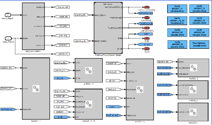
Figure 8 represent the verification model built in simulink that is used for verification and property proving of fuel level display system in Simulink Design Verifier. It contains the block for input assumptions, a block that represent the simulink model of fuel level display system, blocks for all the requirements of fuel level display system that it is supposed to satisfy and a verification button for each requirement.
Figure 8: Simulink Design Verifier - verification model.
Figure 9 represents the model of fuel level display system in Simulink that is to be verified against the requirement and to see whether the requirements are satisfied by the system model or not. In the next section Simulink model of fuel level display system is presented briefly. Complete model of the fuel level display system cannot be presented in this thesis because of the privacy policies of Scania. Scania already has the model of fuel level display system available in simulink but that model covers all the four variants of fuel level display system plus it also covers all the sensor type and all sizes of fuel tank, it also contains some extra features which are not part of the actual system. In order to make the model according to requirements the model is simplified and all the extra details are removed from it. Now the following simulink model is for one system variant, one type of fuel level sensor, one type of fuel tank and where total fuel level is calculated by COO.
GSEEM (Global Software Engineering European Master) 24
7.1. Model of Fuel Level Display system in Simulink Constants
All the values that are written in capital letters in the fuel level display models in Simulink are constants and the following table 6 presents the values of all the constants that are used in fuel level display system model in Simulink and their description.
Constant Value Description Used in
Module PCT_TO_DEC_F32 1/100 Conversion from percentage to decimal. Figure 16 VOLUME_DIFF_ACCEPTED
_F32
0.1 10% volume diff between estimated and sensor value is accepted to use the stored estimate from shutdown as startup value.
Figure 18
NEAR_TOP_PERCENTAGE_ F32
90 Using a limit to always start with the raw sensor value if fuel level is high. This will override the condition that there have to be 10% difference in volume at startup for using the raw value. It is useful when the tank is top-filled with small amounts.
Figure 18
REFUEL_DETECTION_LIMIT _F32
30 Refuel detection. Figure 21
L_PER_H_TO_M3_PER_S_ F32
1/(1000*3600) Liter per hour to m3 per second. Figure 23
LITER_TO_M3_F32 1/1000 Liter to m3. Figure 24,
Figure 26 KALMAN_FEEDBACK_GAIN
_F32
1e-009 * 10780 Kalman gain calculated as specified in AER201.
Figure 25
TS_F32 0.01 COO7 constants. Figure 25
EPSILON_F32 1.1755 e-038 Value used to avoid divide by zero situation.
Figure 27 LOW_IND_RELEASE_LEVEL
_F32
20 Used if a refuel is not detected by the algorithm the low level warning should be turned off.
Figure 30
LOW_FUEL_LEVEL_LARGE _TANKS_F32
7 Percent warning level (large tanks above 900 liter capacity)
Figure 31 LARGE_TANK_LIMIT_F32 900 Above 900bliters theoretical volume is
considered as large tanks.
Figure 31 LOW_FUEL_LEVEL_NORM
AL_TANKS_F32
10 Percent warning level. Figure 31
LOW_FUEL_LEVEL_IND_A CTIVE_U08
uint8(10) Parameter. Figure 33
GSEEM (Global Software Engineering European Master) 25 Due to the confidentiality concerns of Scania this report only contains a small portion of fuel level display system that is modeled in simulink, complete Simulink model of fuel level display system cannot be presented in this report due to the privacy policies of Scania.
Figure 9 presents the block that represents the fuel level display system in the verification model with two main inputs and outputs as shown in the figure 9 below.
Figure 9: Fuel level display system.
When the model present in figure 9 is expanded by double clicking on it then the model that is present in figure 10 below is opened.
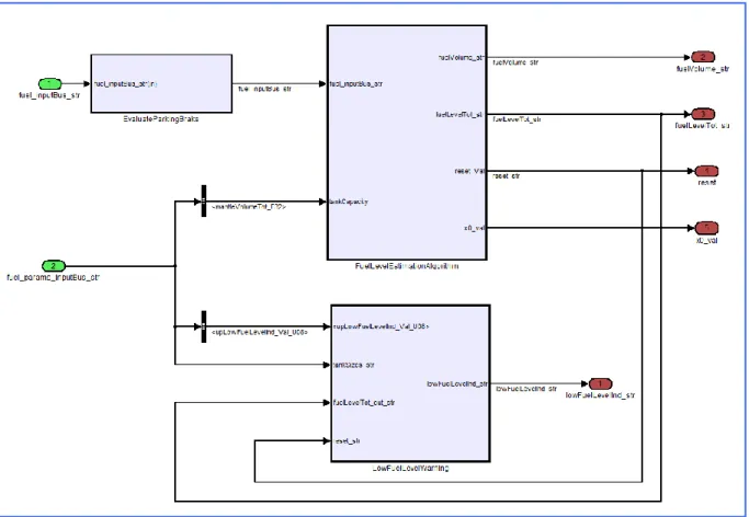
Figure 10: Fuel level display system algorithm.
Model present in figure 10 contains a sub block named algorithm which contains within it the model that is present in the figure 11 below which contains 3 sub blocks representing evaluate parking brake, fuel level estimation algorithm and low fuel level warning.
GSEEM (Global Software Engineering European Master) 26
Figure 11: Fuel level display system algorithm.
Expanding evaluate parking brake sub block presents the following model showed in figure 12, which has a state flow for evaluate parking brake applied.
Figure 12: Evaluate parking brake.
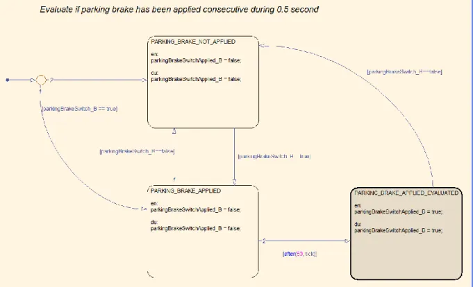
Evaluate parking brake applied state flow contains within it the state flow present in figure 12, which evaluates if parking brake has been applied consecutively during 0.5 seconds.
GSEEM (Global Software Engineering European Master) 27
Figure 13: Evaluate parking brake applied.
Sub block fuel level estimation algorithm in figure 11 contains three sub blocks named calculate current volume levels, algorithm reset calculation and Kalman observer estimation present in figure 14 which can be seen by expanding the fuel level estimation algorithm sub block present in figure 11.
GSEEM (Global Software Engineering European Master) 28
Algorithm reset calculation sub block in figure 14 contains the following model present in figure 15 which contains a state flow called refuel detection.
Figure 15: Algorithm reset calculation.
State flow for refuel detection in figure 15 contains the following state flow present in figure 16 in it that is used to check if refuel is performed or not.
Figure 16: Refuel detection.
The main state in model present in above figure 16 contains the following state flow present in figure 17 that is the actually process for the detection of refuel.
GSEEM (Global Software Engineering European Master) 29
GSEEM (Global Software Engineering European Master) 30
7.2. Input Assumptions
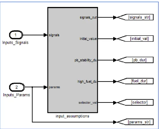
Figure 18 represents the input assumptions block in verification model. Following section represent how the assumptions on input params and signals are defined. Later-on the buttons are used to set the input assumptions for each requirement to be verified by the Simulink Design Verifier.
Figure 18: Input assumptions.
Input assumptions block in figure 18 contains the model present in figure 19 which contains 3 sub blocks params assumptions, signal assumptions and verification selectors.
GSEEM (Global Software Engineering European Master) 31
Figure 19: Input assumptions.
Params assumptions sub block present in figure 19 contains the model present in figure 20. This actually defines the limits on all the input params used in fuel level display system. These are activated and deactivated by using the instructions present behind verification buttons because each requirement require different params not all of them.
Figure 20: Params assumptions.
Signals assumptions sub block present in figure 19 contains the model present in figure 21. This actually defines the limits on all the input signals used in fuel level display system. These are activated and deactivated by using the instructions present behind verification buttons because each requirement require different signals not all of them.
GSEEM (Global Software Engineering European Master) 32
Figure 21: Signal assumptions.
Figure 22 to Figure 26 show how the scenarios are generated for refill and requirement AER-07 (AER202_03). Verification selectors sub block present in figure 19 contains the model present in figure 22 which contains two sub blocks refill scenario and AER202_03 scenario.
Figure 22: Verification selectors.
Refill scenario sub block present in figure 22 contains the model present in figure 23 which contains a state flow refill scenario generator.
GSEEM (Global Software Engineering European Master) 33
Figure 23: Refill scenario.
The refill scenario generator state flow present in figure 23 contains the state flow present in figure 24 which actually describes that how the scenario is generated for the refill.
Figure 24: Refill scenario generator.
AER202_03 scenario sub block present in figure 22 contains the model present in figure 25 which contains a state flow AER202_03 scenario generator.
GSEEM (Global Software Engineering European Master) 34
Figure 25: AER202_3 scenario.
AER202_03 scenario generator state flow present in figure 25 contains the state flow present in figure 26 which actually describes how the scenario is generated for the requirement AER-07 (AER202_03) that is “To verify that he lowFuelLevelWarning should be kept true, once it is activated, until the algorithm is restarted by an ECU shutdown or if the totalFuelLevel reaches above 20%” [15].