Design, Simulate and Prototype Data Decision
System for the Smart Universal Gateway for
e-HealthCare System
Boidi Krishna Verma
THESIS WORK
2011
Design, Simulate and Prototype Data Decision
System for the Smart Universal Gateway for
e-HealthCare System
Boidi Krishna Verma
This thesis work is performed at School of Engineering, Jönköping University within the subject area Electrical Engineering. The work is part of the master’s degree programme with the specialization in Embedded Systems.
The author is responsible for the given opinions, conclusions and results. Supervisor: Youzhi Xu
Credit points: 30 points (D-level) Date:
III
IV
Abstract
V
Sammanfattning
Keywords Universal Gateway Data Decision System Hidden Markov Model Wireless Sensor Networks
Transfer Control Protocol /Internet Protocol Network File System
VI
Table of Contents
1 Introduction ... 1
1.1 BACKGROUND ... 1
1.2 PURPOSE AND AIMS... 2
1.2.1 Requirements Functions of Smart Gateway: ... 2
1.2.2 Smart Universal Gateway Onboard-server functional requirements:... 3
1.3 DELIMITS ... 3
1.4 OUTLINE ... 3
2 Theoretical background ... 4
2.1 WIRELESS SENSOR NETWORKS ... 5
2.2 TINYOS ... 6
2.3 DATA AGGREGATION ... 7
2.4 DATA DECISION SYSTEM ... 9
2.5 HIDDEN MARKOV MODELS ... 10
2.5.1 Stochastic Process ... 10
2.5.2 HMM ... 11
2.6 LINUX SYSTEM INTERFACE SUBSYSTEMS... 13
2.7 REQUIREMENTS SPECIFICATIONS ... 14
2.7.1 Requirements of Simple Universal Gateway... 14
2.7.2 Requirements of Smart Universal Gateway ... 14
2.8 RELATED WORK ... 15
3 Design and Implementation ... 16
3.1 RESEARCH AND DEVELOPMENT METHODOLOGY... 16
3.2 SOFTWARE DEVELOPMENT METHOD ... 18
3.3 ARMLINUX SYSTEM DEVELOPMENT ... 19
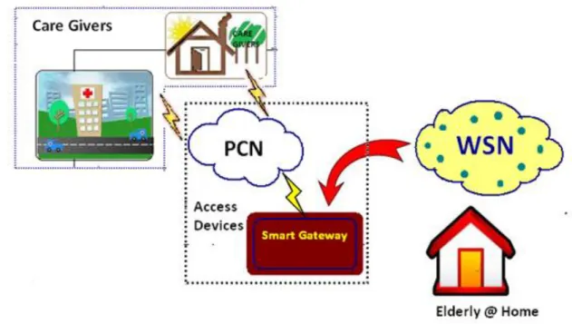
3.4 HEALTH CARE SYSTEM OVERVIEW ... 20
3.5 HARDWARE AND SOFTWARE ARCHITECTURE ... 21
3.5.1 Base Station ... 22
3.5.2 Smart Universal Gateway Development Board ... 23
3.5.3 Boot Loader ... 25
3.5.4 Root File System ... 26
3.5.5 SQLite Database ... 26
3.5.6 Work Flow model of Smart Gateway ... 27
3.5.7 Packet Format between WSN and Gateway ... 30
3.6 SIMULATION OF SMART UNIVERSAL GATEWAY ... 30
3.6.1 Overview of IBM Rational Rhapsody as Simulation Tool ... 31
3.6.2 Flow chart of Functional Smart Gateway ... 31
3.6.3 Hierarchical Use-Case Model ... 33
3.6.4 Functional Use-Case Model ... 34
3.6.5 File Diagram ... 35
3.6.6 Message/Execution Diagram ... 41
3.7 PROTOTYPING OF DDS ON EVALUATION BOARD... 42
3.7.1 Host PC setup for implementation ... 43
3.7.2 File Management System on ARM Evaluation Board ... 44
3.7.3 DDS Prototyping and Deployment on ARM Evaluation Board ... 45
4 Results and Requirements Traceability ... 47
5 Conclusions and Discussions ... 50
6 References ... 51
7 Appendix... 53
7.1 NFS setup on Host PC ... .54
7.2 WSN Data Acquisition into ARM Evaluation Board ... ….55
VII
List of Figures
FIGURE 2-1WIRELESS SENSOR NETWORKS BLOCK DIAGRAM………...5
FIGURE 2-2DIFFERENT POINTLESS AND PROMISING DATA AGGREGATION CASES……….7
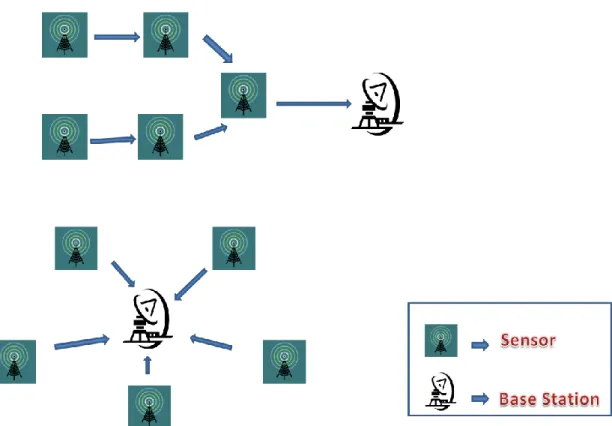
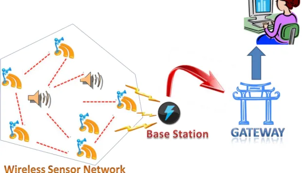
FIGURE 2-3WORKING DIAGRAM OF NODES AND BASE STATION……….…8
FIGURE 2-4BLOCK DIAGRAM OF DECISION SYSTEM …………..……….…9
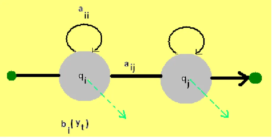
FIGURE 2-5HMM:SHADED NODES DENOTE EMITTING STATE WITH OUTPUT PROBABILITY BI(VT), THE ARCS REPRESENT STATE TRANSITIONS WITH PROBABILITY AIJ….………..…....11
FIGURE 2-6CONCRETE EXAMPLE OF HIDDEN MARKOV MODEL ………...…………..…12
FIGURE 2-7LINUX SYSTEM ON ARMEVALUATION BOARD ……….………….……..………13
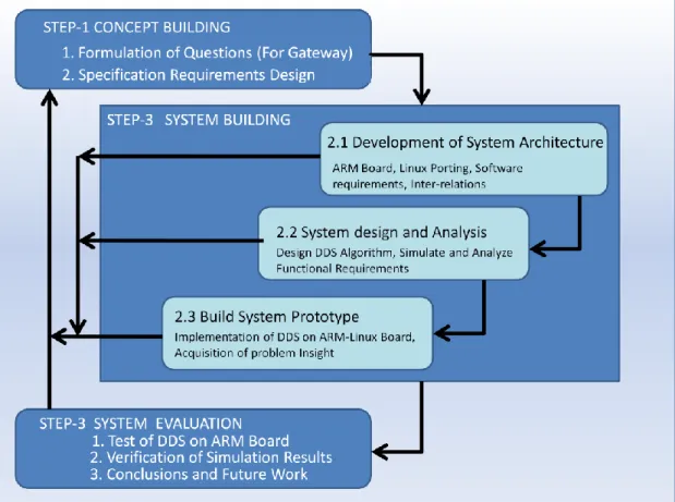
FIGURE 3-1RESEARCH METHOD AND SYSTEM DEVELOPMENT PROCESS ..………..………16
FIGURE 3-2WATER FLOW MODEL FOR SOFTWARE DEVELOPMENT……….……..…………17
FIGURE 3-3EMBEDDED SYSTEM DEVELOPMENT ………..………18
FIGURE 3-4OVERVIEW OF HEALTH CARE SYSTEM……….………..………19
FIGURE 3-5HARDWARE ARCHITECTURE OF ARMBOARD………..………..………20
FIGURE 3-6(A)MIB520USB INTERFACE BOARD AND (B)INTERFACE BOARD ATTACHED TO SINK…...21
FIGURE 3-7ARMEVALUATION BOARD CONNECTION TO HOST PC…….………...……….22
FIGURE 3-8ARMEVALUATION BOARD………...…….23
FIGURE 3-9SQLITE C/C++APIFLOW DIAGRAM……….26
FIGURE 3-10FLOW MODEL WITH SIMPLE FUNCTIONS OF SMART GATEWAY...…...……….27
FIGURE 3-11WORK FLOW MODEL WITH ADVANCED FUNCTIONS OF SMART GATEWAY.…....………28
FIGURE 3-12FUNCTIONAL FLOWCHART OF SMART GATEWAY………31
FIGURE 3-13HIERARCHICAL USE-CASE MODEL………..….32
FIGURE 3-14FUNCTIONAL USE CASE MODEL………..……….33
FIGURE 3-15ABSTRACT UNIVERSAL GATEWAY FILE DIAGRAM………..34
FIGURE 3-16DATABASE_UTIL FUNCTIONAL FLOWCHART………..36
FIGURE 3-17DECISION SYSTEM EXAMPLES FOR BLOOD PRESSURE……….37
FIGURE 3-18WSNTIMER FLOWCHART………38
FIGURE 3-19SHOWWSNDATA FUNCTIONAL FLOW CHART……….39
FIGURE 3-20 SHOWWSNDATA FLOWCHART………....40
FIGURE 3-21SQLITE DATABASE FLOWCHART………...41
FIGURE 3-22ABSTRACT SMART GATEWAY SIMULATION RESULTS 1………42
FIGURE 3-23SMART GATEWAY SIMULATION RESULTS 2………...43
FIGURE 3-24ARMBOARD FILE SYSTEM……….46
FIGURE 3-25DATA DECISION SYSTEM FLOW MODEL………46
FIGURE 3-26SQLITE3DATABASE STARTUP ON ARMBOARD………..47
1
1 Introduction
2
1.2 Purpose and aims
4.
3
1.2.2 Smart Universal Gateway Onboard system requirements:
1.3 Delimits
4
2 Theoretical background
5
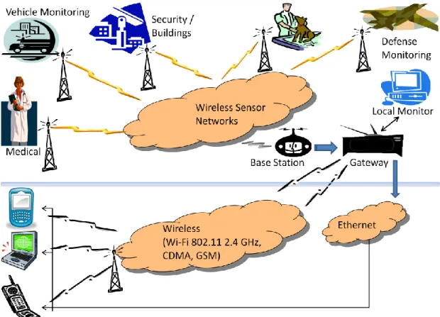
2.1 Wireless Sensor Networks
Figure 2-1 Wireless Sensor Networks Block Diagram
6 b. Data Validity: c. System Reliability: d. System Scalability: .
2.2 TinyOS
7 .
2.3 Data Aggregation
.
8
9
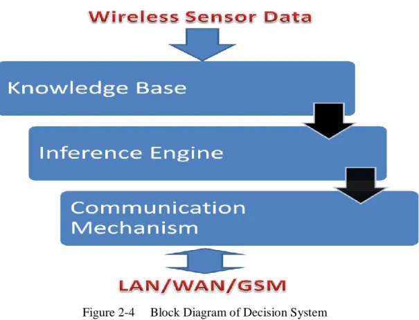
2.4 Data Decision System
10
2.5 Hidden Markov Models
2.5.1 Stochastic Process
11 considering 2.5.2 HMM
Definition of Hidden Markov Model of a stochastic system is a Markov chain
[5] of the system plus some statistical model based on some observed data from a system.
According to the above definition, Hidden Markov Model chain contains of two parts. The first part is the Markov chain which is defined by , where Q states of the Markov chain are not observable, thus hidden. And the second part is the M set of observational symbols Y = {y1, y2, y3...yM } which
are corresponded to the system output being modelled. This correspondence is represented by a matrix B, contains the probabilities of the emitting observations while in state . The below
Figure 2-5 HMM: Shaded nodes denote emitting state with output probability bi(vt), the arcs represent state transitions with probability aij
12
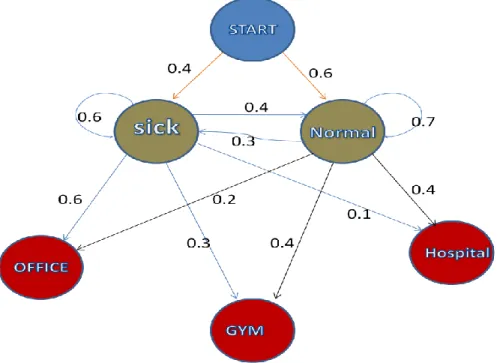
Hidden Markov Models implements complex Markov chains modelled on observational emitted states according to some probability distribution. The below concrete example illustrates the probabilistic state transitions limited to the possible health states of a human being.
Considering the present state of human being stated into set of two variables State = {Normal, Sick}
The above two variables are considered to be probabilistic Markov states in the invisible to care takers and further production states in Hidden State, invisible.
13
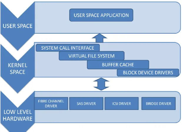
2.6 Linux System Interface Subsystems
14
2.7 Requirements Specifications
2.7.1 Requirements of Simple Universal Gateway
2.7.2 Requirements of Smart Universal Gateway
15
16
3 Design and Implementation
17
18
3.2 Software Development Method
19
3.3 ARM Linux System Development
Figure 3-3 Embedded System Development
20
3.4 Health Care System Overview
21
22
3.5.1 Base Station
23
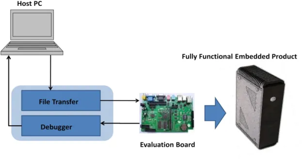
Figure 3-7 ARM Evaluation Board connection to Host PC
The above picture illustrates the ARM Evaluation Board with the Data Decision System Connecting the Base station and Host PC via debugging connections.
24
25 3.5.3 Boot Loader
26
3.5.4 Root File System
3.5.5 SQLite Database
Database engine ported on the ARM evaluation board is SQLite version 3. The reasons for opting SQLite as the Database engine are as following sophisticated facilities that it provides.
Zero Configurations: Initial No-Configuration is required to setup the database. Single binary file with the included library files act as pre-configured database engine, with enough features.
Portability: It is built with consideration of portability issues. Database can be complied on windows and other operating systems such as Linux, Solaris, Mac and other embedded platforms such as QNX, VxWorks, Symbion, and PalmOS etc. It works on 16-, 32- 64- bit architectures with both big-endian and little-endian byte orders. Database file binary format is compatible to all supported Operating Systems. Upon to OS limited capacity, it can hold up to 2 terabyte of data. And supports both UTF-8 and UTF-16 encoding.
Simplicity: SQLite database is built simple; its API is easy to use. It is customized to build our own convenient functions in C. It has vast language libraries related to Python, Perl, Ruby and Java etc. Each module in it is specialized, performing a specific task. Its each module is developed independently and to debug queries as they pass from one module to other. It is also easy to add new features, debug and gain database reliability.
27
Figure 3-9 SQLite C/C++ API Flow Diagram
Flexibility:
SQLite is a flexible database. Being a light database, it provides both facilities such as power and flexibility of a relational database frontend. It requires no database servers to configure, no networking or connectivity problems, no platform limitations, no license fees.
28
29
30
3.5.7 Packet Format between WSN and Gateway
Sensor nodes used in this research have TinyOS-2.0 installed. In TinyOS-2.x, the standard message buffer is called message_t. Frame structure of message_t is shown as below.
Name Destination Address Link Source Address Message Length Group ID Active Message Handler Type Payload Size(bytes) 2 2 1 1 1 User Design Frame head (from destination address to active message type) is used for packet routing in WSN. They are useless to the HCC. Only the “Payload” segment is useful for smart gateway or HCC. We consider the “Payload” segment design is very important to the smart gateway design because, first, it realizes the functions of WSN healthcare system, and second, the data package has the largest transmits number in the WSN. Its designed significantly affects the overall system functionality and efficiency. We designed the Payload format is as shown in below.
Name Mote ID Counting Data Type Data Value Parent ID
16 16 16 8 16 16
We try to keep this payload segment design as efficient as possible. “Mote ID” segment indicates the packet sender’s id. “Counting” segment is the packet sequence number or time stamp. “Data Type” identified the type of data packets. We have considered nine different kinds of data packet for both home sensor network (HSN) and body sensor network (BSN) in our health care system prototype including heart-beat rate, temperature, microphone, Received Signal Strength Indication (RSSI) etc. “Value” segment represents the data type value got by the sensor. “Parent ID” segment indicates the mote ID of the sensor node of the last hop in its transmission path.
3.6 Simulation of Smart Universal Gateway
During this section, we discuss about the modelling of Smart Universal Gateway, Design, Simulation and Software Tools used.
31
3.6.1 Overview of IBM Rational Rhapsody as Simulation Tool
32
33
3.6.3 Hierarchical Use-Case Model
34
3.6.4 Functional Use-Case Model
Figure 3-14 Functional Use Case Model
35
3.6.5 File Diagram
37
3.6.5.1 Universal Gateway Files
38
Figure 3-17 Decision System examples for Blood Pressure
The blood pressure levels comprise of both systolic and diastolic stages and their respective probabilistic sub levels of Decision System. Each and every stage is assigned with Display Notification during prototyping.
39
3.6.5.2 Health Care System Files
Figure 3-19 ShowWSNData Functional flow chart
The above flow chart illustrates the process of data acquisition and storage of WSN payload data in SQLite3 database in the evaluation board. WSN data is displayed when WSNDataREQUEST event is triggered, The payload conversions are done within this function.
40
Figure 3-20 showWSNData Flowchart
3.6.5.3 Database Administration State chart Files
41
The above illustrates the flow model of the SQlite3 database ported in the ARM Evaluation Board. Database utilization comprises of the stages such as Database Initiation, OpenTable, callback, updateDatabase, cleanJunk and CloseDatabase.
3.6.5.4 WSN Networks
3.6.6 Message/Execution Diagram
Figure 3-22 Smart Gateway Simulation results 1
The above execution diagram is an animation of simulation output. With the evSysOn(), the smart Universal Gateway System turns ON. The aggregated data from the Base-Station is driven into the Smart Universal Gateway. WSNOFF or WSNON alarms are displayed if the Base-Station connection to the Smart Universal Gateway is OFF or ON respectively.
1) When the Gateway System is ON, the Database_Utility retrieves the data from the WSN nodes, opens the tables created, updates it with the data from them and closes Database.
42
2) The Data Decision System manipulates the data saved in the database, creates Alarms and Messages, and will display it to the Care Centre.
Figure 3-23 Smart Gateway Simulation Results 2
43
3.7.1 Host PC setup for implementation
3.7.1.1 Cross Compiler Setup
44 tar –xzvf sqlite-3.5.2.tar.gz Cd sqlite-3.5.2
./configure –enable-threads make
dllwrap –dllname sqlite3.dll –def sqlite3.def *.o
dlltool –def sqlite3.def –dllname sqlite3.dll –output-lib sqlite3.lib
45
ARM Evaluation Board File System appears as below shown;
Figure 3-24 ARM Board File System
46
Figure 3-25 Data Decision System Flow Model
3.7.3.1 SQLite Database porting on ARM evaluation board
Figure 3-46 Sqlite3 Database Startup on ARM Board
47
Figure 3-27 WSN Payload Bit stream in ARM Board
4 Results and Requirements Traceability
48
4.2 Functional Requirements traceability
Elderly’s Name: Dedor Behanet,Age -60, E44 Ostratorp, 52345 Skövde, Sverige.
Data Acquisition : Blood Pressure, Pulse Rate
High Priority: SMS and Voicemail to Health Care Medium Priority: Intimate CareGivers at Elderly’s Home Low Priority: Questionable Events in variable data;
49
50
51
53
7 Appendix
7.1 NFS setup on Host PC
Initially, the below commands are used to install the NFS and Portmap software.
sudo apt-get install nfs-kernel-server nfs-common portmap
Configuration of the Portmap is followed and loopback issues can be corrected by editing “/etc/default/portmap” using below commands;
sudo vi /etc/default/portmap or sudo dpkg-reconfigure portmap
Finally, restart Portmap by the command
55
7.3 Sqlite3 Database Compilation & Porting on ARM
Board
Compile SQLite using the cross-compiler such as arm-linux-gcc first, get sqlite-3.3.6.tar.gz from www.sqlite.org
unzip it,
#tar -zxvf sqlite-3.3.6.tar.gz
change into the sqlite-3.3.6 directory cd sqlite-3.3.6
make a new directory such as 'build' under sqlite-3.x.x directory,
open the configure-script using your favorite text-editor ,such as:
#vi configure
I recommend that you make a copy of configure before editing the configure file
cp configure configure.old and edit the configure.
Comment out the following commands by putting a '#' in front of them(looks like):
#if test "$cross_compiling" = "yes"; then
# { { echo "$as_me:$LINENO:: error: unable to find a compiler for building build tools" >&5
#echo "$as_me: error: unable to find a compiler for building build tools" >&2;}
56 # { (exit 1); exit 1; }; }
#fi #else
# test "$cross_compiling" = yes &&
# { { echo "$as_me:$LINENO:: error: cannot check for file existence when cross compiling" >&5
#echo "$as_me: error: cannot check for file existence when cross compiling" >&2;}
# { (exit 1); exit 1; }; } . . .
#else
# test "$cross_compiling" = yes &&
# { { echo "$as_me:$LINENO:: error: cannot check for file existence when cross compiling" >&5
#echo "$as_me: error: cannot check for file existence when cross compiling" >&2;}
# { (exit 1); exit 1; }; }
Save the configure script, change into the build directory you created and call the edited configure script from the sqlite directory by using the following option:
../sqlite/configure --disable-tcl --host=arm-linux
after that, configuration should have created a Makefile and a libtool script in your build directory.
Open the Makefile using your favorite text editor and find the following lines:
BCC = arm-linux-gcc -g -O2 change to
BCC = gcc -g -O2
The reason for these changes is that the created files have to be executed on the PC during the compilation, so we have to compile them with the standard gcc and not the arm-linux-gcc. if you want compile static library version of sqlite3(only one execute file for distribution) on ARM, edit Makefile ,
find
sqlite3$(TEXE): $(TOP)/src/shell.c .libs/libsqlite3.la sqlite3.h change to
sqlite3$(TEXE): $(TOP)/src/shell.c .libs/libsqlite3.a sqlite3.h find
-o $@ $(TOP)/src/shell.c .libs/libsqlite3.la \ change to
57
-o $@ $(TOP)/src/shell.c .libs/libsqlite3.a \ save and quit editor
run 'make' command to create the sqlite3 execute file, after a successful compile,Now you should find a hiden “.libs”
directory in your build directory containing sqlite shared object files, like libsqlite.so or static libray files like
libsqlite3.a .
run 'arm-linux-strip sqlite3' to decrease the execute file size. upload the sqlite3 to target ARM9 board by any FTP client and make it executive:
on ARM Evaluation Board with terminal or telnet ,run chmod 775 sqlite3
and then run sqlite3 like this sqlite3 ex2 or
Enter into the folder location of SQLite3 database and enter the following command
./sqlite3
,if you see the following messages: porting is Successfull SQLite version 3.x.x
Enter ".help" for instructions sqlite>