Postal Address: Visiting Address: Telephone:
Box 1026 Gjuterigatan 5 036-10 10 00
551 11 Jönköping
Simulation of a Clinch Unit by using Cosmos
and Abaqus
Jonathan Björn
THESIS WORK 2007
Postal Address: Visiting Address: Telephone:
Box 1026 Gjuterigatan 5 036-10 10 00
551 11 Jönköping
Simulation of a Clinch Unit by using Cosmos
and Abaqus
Jonathan Björn
This thesis work is performed at Jönköping Institute of Technology within the subject area Machine Technology. The work is part of the university’s master’s degree. The authors are responsible for the given opinions, conclusions and results.
Supervisor: Niclas Strömberg Credit points: 20 points (D-level) Date:
Abstract
1
Abstract
The following report contains an evaluation of the use of mathematical simulation programs at the company Isaberg Rapid AB. The work includes booth FE and motion simulations where the results are compared with real life test data.
The goal of the report is to evaluate the accuracy of simulations which can be performed by engineers as a part of the design process. By using mathematical simulation tools it is possible to find a good design solution early in the development phase and thereby shorten lead time and reduce costs.
Summary
2
Summary
The goal of the following report was to evaluate the use of mathematical simulation at Isaberg Rapid AB. This was done to see if the tools available at the company, CosmosWorks and CosmosMotion, can deliver accurate results in an easy way. By using simulation software the engineer can find the right solution earlier in the design process and thereby reduce cost. A real life case, where the motion of a clinch unit inside an automatic stapler lead to a collision and later a fatigue failure, was examined using booth analytical calculations, simulation software and measured data. The results were then compared to see if the
behaviour of the moving parts could have been predicted and if the fatigue failure could have been prevented.
The comparison showed that using CosmosWorks and CosmosMotion can give you a good description of the behaviour of dynamic events though it relies a great deal on the inputs the engineer makes. The programs must not be seen as a magic box containing all answers but tools which should be a part of a creative process.
By calculating the impact force on the clinch housing wall using CosmosMotion, an FE stress analysis could be performed in CosmosWorks. The maximum stress in the simulation
occurred in the same location as fracture in real life.
The housing design featured small fillets that can lead to high stresses. FE-calculations early in the design process would have made this visible. The warning sign could have led to a decision to use a different design solution and perhaps thereby avoiding the fatigue failure. The analytical calculations showed how a design solution could be evaluated and the result used as a risk assessment but also the difficulties in creating a good approximation of real life conditions. Play because of tolerances and friction between parts are hard to predict or
estimate, but may have a large impact on the results. Great product insight is required to create accurate assumption for the calculations.
A series of guidelines were produced to be used in future projects at Isaberg Rapid AB. They stress the need of clear goals when creating an analysis and that the result is never more accurate than the input data.
Keywords
Table of contents
3
Table of contents
1 INTRODUCTION ... 5
1.1 PURPOSE AND AIMS ... 5
2 METHOD ... 6 3 BACKGROUND ... 7 3.1 PRODUCT DESCRIPTION ... 7 3.1.1 Market ... 7 3.2 FUNCTION ... 8 3.2.1 Clinch unit ... 9 3.2.2 Power unit ... 10 3.2.3 Chassis ... 13 3.2.4 Stapler unit ... 14 3.2.5 Electrical system ... 14 4 PRODUCT TESTING ... 15 4.1 CLINCH POSITION ... 15 4.2 UNLOCKING FORCE ... 15 5 MECHANICAL SYSTEM ... 16
5.1 SCISSORS AND CAM ... 16
5.2 LOCKING PLATE... 17
5.3 STAPLE BRACKET LOCKING ... 17
6 DETAIL DESCRIPTION ... 18
6.1 CLINCH HOUSING ASSEMBLY ... 18
6.1.1 Connectors ... 19
7 ANALYTICAL MODEL ... 20
7.1 PROBLEM STATEMENT ... 20
7.2 PART I ... 20
7.2.1 Assumptions ... 20
7.2.2 Unknowns and given values ... 21
7.2.3 Free body diagram ... 22
7.2.4 Laws of motion ... 22
7.2.5 Results ... 23
7.3 PART II ... 24
7.3.1 Assumptions ... 24
7.3.2 Unknowns and given values ... 24
7.3.3 Free body diagram ... 25
7.3.4 Kinetic relations ... 25
7.3.5 Results ... 26
7.3.6 Parameter study ... 27
8 COSMOSMOTION SIMULATION... 28
8.1 BACKGROUND ... 28
8.1.1 Rigid body dynamics ... 28
8.1.2 MSC ADAMS/Solver ... 29
8.1.3 Joints and Constraints ... 29
8.2 PROBLEM STATEMENT ... 30
8.3 MODELING ... 30
8.4 RESULTS ... 31
9 RESULT COMPARISON ... 32
Table of contents
4
9.2 COSMOSMOTION SOLUTION AND TEST VALUES ... 33
10 FE-MODEL ... 34
10.1 BACKGROUND ... 34
10.1.1 FE formulation ... 34
10.1.2 Elements ... 35
10.1.3 CosmosWorks solvers ... 36
10.1.4 CosmosWorks mesh creation ... 37
10.2 CLINCHING STRESS AND STIFFNESS CALCULATION ... 38
10.2.1 Element type and solver ... 38
10.2.2 Model ... 38
10.2.3 Stiffness calculation and convergence study ... 39
10.2.4 Stress calculation ... 41
10.3 IMPACT STRESS AND STIFFNESS CALCULATION ... 42
10.3.1 Element type and solver ... 42
10.3.2 Model ... 42
10.3.3 Stiffness calculation ... 43
10.3.4 Stress calculation ... 44
11 NONLINEAR DYNAMIC SIMULATION ... 48
11.1 IMPLICIT AND EXPLICIT METHOD ... 48
11.2 COSMOSWORKS 2008 ... 49
11.2.1 Element type and solver ... 49
11.2.2 Model ... 49
11.2.3 Mesh ... 50
11.2.4 Results ... 50
11.3 ABAQUS ... 52
11.3.1 Element type and solver ... 52
11.3.2 Model ... 52
11.3.3 Mesh ... 53
11.3.4 Results ... 53
12 CONCLUSIONS AND DISCUSSIONS ... 56
13 GENERAL GUIDELINES ... 60
13.1 THE DESIGN PROCESS ... 60
13.2 REQUIREMENTS ... 61
13.2.1 Formulation of the problem ... 61
13.2.2 Type of analysis ... 62
13.2.3 Result handling ... 63
14 REFERENCES ... 65
15 ATTACHMENTS ... 66
I-GEAR RATIO ... 66
II-DIFFERENTIAL EQUATION IN MATLAB ... 67
III-LOCKING PLATE GEOMETRY ... 70
IV-CLINCH POSITION ... 72
Introduction
5
1 Introduction
1.1 Purpose and aims
The purpose of the following report is to evaluate the use of mathematical simulation in the engineering design process at Isaberg Rapid AB. Until now the design process have been carried out on a trial and error basis and therefore an evaluation of the capabilities of
mathematical simulation is launches in order to search for way to decrease booth project time span and costs as well as secure reliability of the products. By using mathematical simulation the final product design can be found earlier in the engineering process and reduce, but not replace, the physical product test sessions.
The subject of the study is a 100 sheet stapler currently delivered to be installed inside a copy machine made by an OEM customer of Isaberg Rapid. The stapler is a high speed machinery and one of the components, called the clinch housing, is subjected to a fatigue failure. The specific purpose of this report is to see if, by using the simulation software CosmosMotion and CosmosWorks as well as hand calculation, the cause of the fatigue failure and the behaviour of the staple can be accurately predicted.
In collaboration with Isaberg Rapid four aims was established:
Shorten lead times and reduce costs in the product design process by using simulation software
Evaluate the possibilities and limitations in CosmosWorks and CosmosMotion o Would it have been possible to predict the impact between the clinch unit and
the housing wall?
Comparison between calculations and real life data o Impact calculation
o Clinching force
Create general guidelines/work method
The aim of the report is to be able to compare results from analytical models, physical tests and simulation software in order to evaluate the accuracy and secure the use of simulations of similar setups. Practical guidelines based on the experience gather during the project will be created, to be used by the company in the future. The long term goal of the company is to reduce lead times and costs in the engineering design process.
Method
6
2 Method
In the late spring of 2007 a meeting was held at Isaberg-Rapid where the problem with the 100 sheet stapler was presented. It was decided that the project should be carried out at the company during the fall and that the task should be divided into two parts. Part one should be the actual analysis of the product and by having a progress check-up in mid fall, part two would either consist of the creation of guidelines or a more detailed analysis preformed at Jönköping University. The content of part two of the project should be based on the results of part one.
The work started in August with a brainstorming period where possible questions and focal points where stated. This led to a meeting with the involved personnel at Isaberg-Rapid where the final purpose and aims was stated and put to paper. Together with the supervisor the tasks to be performed during the first part of the project was determined:
Create a detailed product description of the stapler
o To be used as a basis in the judgement of the assumptions made in the calculations
Create an analytical model of the impact scenario
Perform motion analysis in CosmosMotion and FE-analysis in CosmosWorks The product description was created by the help of a working stapler where the motor had been replaced with a handle, making it possible to view the stapling cycle in low speed and establish the relationship between the different moving parts.
The analytical models were created using the approaches described in (Meriam, 2007), (Meriam, 2007) and (Nyberg, 2003) and the assumptions made was based on the information gathered for the product description.
In order to simulate the impact scenario a combination of CosmosMotion and CosmosWorks was used. To evaluate the result two more simulations where created in CosmosWorks 2008 and ABAQUS, where a nonlinear dynamic setup could be used.
To summarise the knowledge gathered during the project a chapter called General Guidelines was created. It can act as a guide to the company Isaberg-Rapid in future projects.
Background
7
3 Background
3.1 Product description
Figure 1 – 100 sheet stapler
The machinery that is the subject of this study is situated in the 100 sheet stapler (Figure 1) currently delivered by Isaberg-Rapid to an OEM Customer and the product is mounted inside a module of a copying machine. It is one of the fastest staplers in the world and can process approximately 1 bundle of paper per second and each bundle can consist of up to 100 papers. These specifications put very high demand on the design with respect to wear, because of the high velocities on moving components and the forces required to punch through a tick bundle of paper.
3.1.1 Market
The project was started in 1997 after an inquiry from an OEM Customer. The projected demand of the product was very high fit volumes up to 100000 machines / year. The high speed of the machine would lead to a high consumption of stapler cassettes, which would have secured the investment.
In reality when the product was launched, 5000 units were sold the first year and the sales have decreased since then. The projection for 2008-2009 is only 2000 sold units.
Background
8
3.2 Function
Figure 2 - Exploded view
The stapler have three main functions: to form the flat staple to its square form, punch it through the paper bundle and fold the legs of the staple. The different components can by divided into four categories or assemblies: the stapler unit (4) which hold the flat staples and the bending and punching mechanism, a moving clinch unit(3) that form the legs of the staple and the power unit(2) containing the motor and gearings. These three assemblies are mounted to a chassis unit(1), which also holds electrical components. An exploded view of the stapler is shown in Figure 2. Booth the clinch and the power unit move with the respect to the chassis during the staple procedure. The motion of the power unit drive the staple unit and the clinch unit moves to form the staple legs and clear way for new paper bundles. This configuration is called the pliers principle and it secures that no extensive forces appear in the chassis unit when the staple is pushed through the bundle, instead they are concentrate inside the stapler and clinch unit.
The stapler unit holds a cassette of flat staples, when the cassette is empty the whole unit is replaced. Many of the components that are subjected to wear are thereby replaced.
The project will revolve around the clinch and the chassis unit, therefore no detailed explanation of the mechanism inside the stapler will be included in this report.
Background
9
3.2.1 Clinch unit
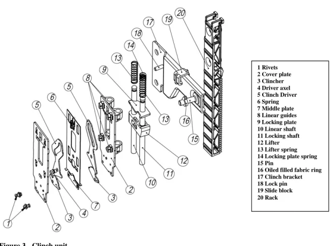
Figure 3 - Clinch unit
The clinch unit assembly (Figure 3) move vertically inside the chassis during the process except for the two shafts (10, 11), which are mounted in the chassis. The actual clinch, that contain the bending mechanism, can move both together with the rack and by itself, but only in vertical direction along the shafts.
Between the two Cover Plates lies the bending mechanism, which is a scissors construction combined with a cam system. When the Pin on the Clinch Bracket presses on the Clinch Driver, the Driver pivots and pushes the Clincher which performs the actual bending of the staple. To prevent wear on the pin, an oil filled Fabric Ring is mounted around it. There is one clincher and driver for each leg of the staple and they are displaced in order to prevent the bent down legs to hit each other, when using long staples through a thin paper bundle.
Because of the amount of processed bundles per second the clinch unit has to be cleared from the bundle very quickly. This is why there are two Lifter Springs mounted on the Linear and Locking Shafts. While bending the staple, the clinch is locked on to one of the shafts, by the Locking Plate. When in a horizontal position the clinch can slide along the shafts but when the locking plate is tilted it prevents movement upward, the effect is improved by a ledge on the locking shaft and the plate is held in position by the Locking Plate Spring. When the clinch bracket moves upwards it pushes the Lifter on to the Locking Plate and thereby releases to lock, sets the springs free which catapults the clinch upward.
1 Rivets 2 Cover plate 3 Clincher 4 Driver axel 5 Clinch Driver 6 Spring 7 Middle plate 8 Linear guides 9 Locking plate 10 Linear shaft 11 Locking shaft 12 Lifter 13 Lifter spring 14 Locking plate spring 15 Pin
16 Oiled filled fabric ring 17 Clinch bracket 18 Lock pin 19 Slide block 20 Rack
Background
10
When the clinch hits the paper bundle the clinchers has to be aligned horizontally to prevent damage. This is secured by the Middle Plate which holds them in position by being pushed down by a spring supported by the cover plates.
3.2.2 Power unit
Figure 4 - Power unit
The power unit (Figure 4) consists of the motor, staple bracket, gears and support plate along
with some structural element and sliders. When the motor starts to rotate the unit is locked to the chassis by a plastic lock on the chassis unit and the rack with the clinch bracket and clinch start to move. When the motion is held back by the clinch touching the paper bundle, the entire power unit instead starts to climb the rack. While doing this the staple bracket press on the stapling unit and thereby enable it to push the staple through the paper bundle and to form a new wire to a square form. To prevent wear on the staple bracket it is separated from the chassis by five plastic sliders.
3.2.2.1 Gears
The purpose of the gear system is to transform the rotation of the engine shaft into a
translational motion. First the speed is changed by a number of spur gears and then the final motion is accomplished by a rack and pinion gear. The gear final gear ratio is 33:4 and the velocity of the rack is given by multiplying the angular velocity by the diameter of the last gear (Attachment I). The gear attached to the motor is made out of brass while the two other gears and the rack are made of plastic.
1 Plastic sliders 2 Staple bracket 3 Motor 4 Gear shafts 5 Spur gears 6 Plastic Steering 7 Rivets 8 Mounting shafts 9 Cover
Background
11
3.2.2.2 The motor
The entire product is powered by a 36 V electrical motor. The motor is controlled by an advanced control system, which has to secure that the power isn’t unleashed at the wrong moment. Should this happen it would cause serious damaged to the gear components and clinch unit because of the high power. Because of the design of the stapler- and clinch-system the motor rotation is reversed in the middle of the stapling sequence. The control system senses when it is time to switch direction and decelerates the motor, but because of the short period of time of the whole procedure it is impossible to come to a complete stop before the current is switched. This of course puts a lot of load on the motor and gear components.
Figure 5 - Engine RPS
As shown in Figure 5 the velocity changes during the stapling procedure. The data is given by the company and has been used to calculate the velocity of the clinch bracket. The velocity is given by the ratio of the gears and a derivation can be found in Attachment I. Figure 6 shows the change in clinch velocity with respect to time.
Background
12
Background
13
3.2.3 Chassis
Figure 7 - Chassis
The design of the chassis (Figure 7) is governed by parameters given by the customer in order for the product to fit inside the copy machine. It consists of three main parts: two sheet metal plates which support the power and the clinch unit and a plastic section that holds the staple unit and electrical components. The above picture also shows the plastic lock which holds the power unit in place in the beginning of the stapling procedure. The lock is snapped on to the cover plate. Because of the aim of the simulation no detailed description will be made of the plastic section or the cover plate, instead focus will be on the clinch housing assembly.
3.2.3.1 Cover plate
The cover plate is the main structural element providing rigidity to the product. The staple unit and the plastic section with electrical components are bolted on to the cover plate using standard torx screws. Because of the pliers principle no forces from the actual stapling procedure is transferred to the cover plate.
1 Cover plate 2 Plastic lock 3 Clinch housing assembly 4 Plastic section
Background
14
3.2.3.2 Clinch housing assembly
The clinch housing holds the clinch unit and it is where the linear and looking shafts are mounted. It also contains the staple bracket locking mechanism, there is also a bracket that makes it possible to adjust the alignment of the staple unit.
It is not subjected to any forces while the staple is formed and then pushed through the paper, but when the staple legs are bent down, it is the locking plate that locks the clinch on to the locking shafts. This leads to a pressure on the housing wall where to shaft is mounted.
Another stress appears when the lock is released the springs catapult the clinch upwards until it hits the top wall of the clinch housing.
3.2.4 Stapler unit
The stapler unit (Figure 8) holds the not yet formed staple rods wire in a replaceable cassette. The parts which are subjected to wear in the bending procedure are mounted inside the cassette and are replaced when the cassette replaced. There are two different types of cassettes, which contain wire for stapling through up to 100 papers and one cassette with shorter wire suited for bundle of up to 30 papers. At rest there is a formed staple in the outlet, ready to be punched through the paper bundle. During the stapling procedure the preformed staple starts to penetrate the bundle while a new staple is formed.
3.2.5 Electrical system
The machine incorporates a number of electrical components such as switches and sensors as well as the interface that connect it to the copying machine. All the information is processed by a computer processor fitted on the electrical chip mounted in the plastic section. It is able to sense when the staple bracket locking is engaged and when it is time to change the rotation of the engine. There are features to secure that the wire is properly formed and ready to be stapled through the paper bundle and when it is time to replace the staple unit. There are also two switches that sense the start and stop of the penetration of the paper bundle.
Product testing
15
4 Product testing
To validate the analytical calculation and the simulation performed in COSMOS Motion test data had to be collected. A number of tests had already been performed at the company and those values were assumed to be accurate.
4.1 Clinch position
Before the product is delivered it undergoes a validation test to ensure its performance. This is done in a rig where the position of the clinch unit is mapped by a laser and the power
consumption is recorded. The information is saved to a data file and plotted by the test software. For this project the position of the clinch unit with respect to time was vital.
Therefore a test session was carried out using the highest sampling frequency available by the test software and the data was imported into Matlab for examination. The function of the laser and the mapping software were assumed to be accurate and the only source of error is
vibrations in the test rig.
For complete position and velocity plots see Attachment IV.
4.2 Unlocking force
The force transmitted to the clinch housing during the clinching procedure is assumed to be equal to the force required to unlock the locking plate and catapult the clinch upwards. A test session had been performed by the company to measure the required force for different configurations of locking shafts and clinch housings. The test was performed by placing a hook in the rack of the clinch unit. The hook pulled the clinch bracket upwards and the force was gradually increased until the lock was released. The deflection of the clinch housing was also measured.
The data in Table 1 is valid for the current configuration of clinch and shafts.
mean
Unlocking force (N) 53 49 48 51
Deflection (mm) 0.38 0.38 0.38 0.38
Table 1 - Unlocking force
As the study of the locking plate later shows, the assumption made that the unlocking force is equal to the load on the clinch housing is incorrect.
Mechanical system
16
5 Mechanical system
1. The motor drives the rack, clinch bracket and the clinch downwards.
2. The clinch hits the paper bundle which stops the motion of the rack, instead the power unit starts to climb upwards on the rack after it has overcome the locking force of the plastic snap lock.
3. The staple bracket in the power unit pushes on to the stapling unit an there by starts to push the preformed staple through the bundle. At the same time the bending
mechanism starts to form a new staple.
4. The staple is pushed through the paper bundle and meets the clincher. The clincher is stationary but the legs of the staple starts to form. The new staple is finished and rests in the outlet of the staple unit.
5. When the power unit has reached its top position it locks onto the chassis by the staple bracket lock. This tells the electrical system to put the engine in reverse
6. The engine is put to reverse.
7. The clinch bracket presses against the scissors and cam system and the staple legs are bent down to the paper into their final position by the clinchers
8. The rack and the clinch bracket continue upwards and the lifter hits the locking plate which has stopped the clinch from moving up during the scissors and cam movement. 9. The clinch is pushed up by the springs
10. When the rack and clinch bracket are at its top position the lock pin pushes onto the staple bracket lock which releases it and the power unit starts to travel downwards to its initial position.
5.1 Scissors and cam
When the clinch bracket pin moves upwards it pushes on the clinch driver which starts to rotate about the driver axel (Figure 9). The tip of the driver forces the clincher to rotate and the staple legs are bent. When the clinch unit first hit the paper bundle it is the cover plates that restrict the position. To secure that the legs are folded flat to the paper the two clinchers will move outside the cover plates pushing on to the staple and staple unit and creating a forced displacement of the entire clinch unit. This displacement is held back by the locking plate and thereby transferred through the locking shaft to the clinch housing.
Mechanical system
17
When the locking plate is released the scissors mechanism moves from a closed to an open position while the whole clinch unit translates upwards. At low engine velocities the motion is restricted by the pin and clinch bracket, but at high speeds booth the pin and lifter springs will catapult the clinch unit upwards resulting in a collision with the housing.
5.2 Locking plate
While the staple legs are being bent by the clinchers the clinch unit is held in place by the locking plate. The plate is tilted by the spring and thereby grips onto the locking shaft. While moving downwards the plate slides on the shaft but when it tries to move upwards the plate locks.
The initial locking force is decided mainly by the stiffness of the spring and geometrical attributes such as the relationship between the shaft and the plate hole diameter, the angle of incline of the plate and the thickness of the plate. To ensure movement of the clinch unit during the start and the finish, the top of the locking shaft has a smaller diameter than the lower part where the locking plate grips. The friction between the plate and shaft can be neglected because they are lubricated by oil.
When the lock is engaged the plate is tilted approximately 5 deg. The force generated during the clinching procedure is applied in the upwards direction on the right tip of the plate and thereby tries to rotate the plate but instead the plate grips to the locking shaft. The higher applied force the more will the plate lock on the shaft. The highest force will be generated at the end of the scissors cam movement when the clinchers are moving outside the cover plates. Practical tests have been carried out to measure the locking force with respect to different dimensions of the shaft and some of the results are used when calculating the locking force in Part II of the analytical model.
5.3 Staple Bracket Locking
When the power unit reaches its top position it is locked in place. This makes it possible for the clinch unit to move upwards when the engine is put in reverse. If the lock was omitted, either the clinch or the power unit would move when the engine rotates. Now it is ensured that only the clinch unit moves.
As the lock snaps into the slot in the staple bracket it engages an electrical switch which tells the computer system to put the engine in reverse.
Detail description
18
6 Detail description
6.1 Clinch housing assembly
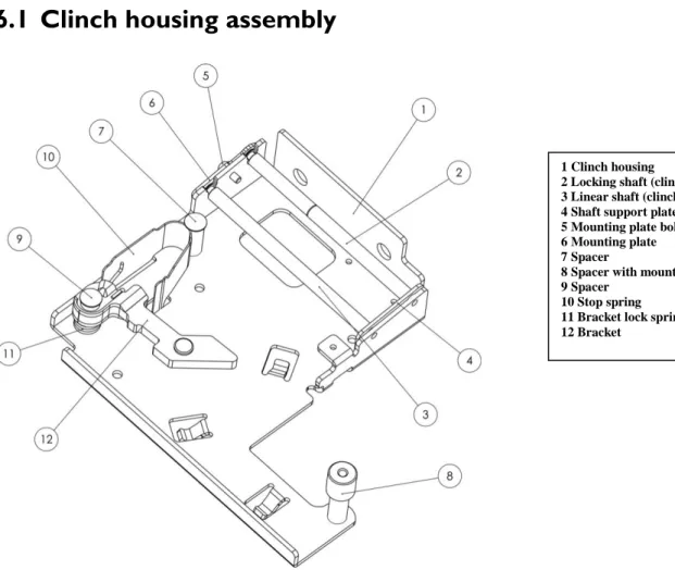
Figure 10 - Clinch housing
The clinch housing (Figure 10) is made out of 2 mm alloy steel which is formed by punching and bending. The shaft support plate is spot welded in place and act as a lower mounting for the linear and locking shaft. The shafts are only fixed at the top of the housing by the shaft mounting plate the enable flexibility in the structure. The mounting plate is made out of hardened steel to withstand wear because of movement of the shafts. In earlier versions of the product the shafts was fixed on the lower flange but his put a lot of stress on the housing because of bearing value stress.
The outer bend radius of the housing is 2 mm and the inner radius has been reduced to a sharp edge by the bending tools to ensure that the different tolerances are kept. This approach is used instead of “over bending” the flange to compensate the elastic retraction.
The two shafts of the clinch unit are made of hardened steel and are finely turned to its correct dimensions and the tolerances are high because of the small ledge on the locking shaft.
1 Clinch housing
2 Locking shaft (clinch unit 11) 3 Linear shaft (clinch unit 10) 4 Shaft support plate 5 Mounting plate bolt 6 Mounting plate 7 Spacer
8 Spacer with mounting 9 Spacer
10 Stop spring 11 Bracket lock spring 12 Bracket
Detail description
19
6.1.1 Connectors
Figure 11 - Connectors
A FE model of the clinch housing is used to calculate the stiffness of the upper housing wall when subjected to an impact force from the colliding clinch unit and an elastic deformation caused by the clinching procedure. In order to describe the model correctly boundary conditions are derived from real life connectors (Figure 11).
The clinch housing is joined to the rest of the chassis unit in four places (8,9,11,14). The three spacers are riveted into the cover plate of the chassis and screwed to the housing using
standard M3 torxs and 8x0.5 mm washers. The spacer mounted in hole 9 is also used to mount the stapler in the copying machine.
1 Tool guides 2 Tool guides 3 Tool guides 4 Tool guides 5 Support plate alignments 6 Support plate alignments 7 Adjustment bolt 8 Bolt 9 Spacer 10 Mounting rivet 11 Spacer
12 Stop spring cut out 13 Mounting rivet 14 Spacer
Analytical model
20
7 Analytical model
7.1 Problem statement
The goal of the analytical model is to find the forces applied to the clinch housing. The model will be based on the theory that two different loads affect the housing wall. When the staple legs are formed, the clinch is held down by the locking plate which locks to the locking shaft. This locking force is transferred to the housing wall where the shaft is fixed and it reaches its maximum just before the lock is released. The second stress appears when the clinch unit collides with the wall after the locking plate springs have been released. Because of the pliers principle no large forces are subjected into the chassis while pushing the staple though the paper bundle. Therefore the analysis of the stapling process will be performed from the time the engine is put into reverse until the clinch unit hits the housing wall.
The analysis of the clinch unit will be divided into two parts. First the final velocity when it collides with the housing will be derived by looking at the unit from the time the locking plate is released until it hits the wall. In Part II the reaction force in the housing wall from the time the engine is put in reverse until just before the lifter hits the locking plate will be calculated.
7.2 Part I
The goal of Part I is to map the velocity of the clinch unit and to calculate the impact force when it hits the clinch housing wall. By stating the governing differential equation of the system, the problem then can be solved numerically in Matlab.
7.2.1 Assumptions
The problem is handled as a linear motion of a system of two particles, the weight of the clinch unit is concentrated into a point (Figure 12).
The friction between the guides and the shafts will be neglected as well as the influence of the scissors and cam mechanism. The scissors and cam mechanism will move from a closed to an open position during to upward motion but all the joints are assumed friction less and opening is aided by the guide plate spring. Overall the effect of the mechanism is assumed to be very small compared to the motion of the pin, clinch bracket and the lifter springs.
The motion of the clinch unit is restricted by the movement of the pin and the clinch bracket. They can move independently but the distance between them is limited by the bottom linear guides hitting the lifter. If the gap in which the clinch can move with respect to the pin is covered before the clinch hits the housing wall, it will instead collide with the lifter moving with the pin. This collision is assumed to be plastic, all the energy loaded in the lifter springs is lost and from that point the
Lifter Clinch unit Clinch housing wall
y
δ u
m
Analytical model
21
clinch will move with the same velocity as the pin until the pin has reached its top position. This will not result in a collision with the housing.
At high speeds the clinch unit pin will hit the housing wall before the gap is covered and it hits the lifter, it is assumed that all energy from the clinch, booth kinetic and elastic is transferred to the wall. The deformation behaviour of the wall is assumed to be elastic and therefore can be described as a linear spring:
7.2.2 Unknowns and given values
The geometry of the structure is known which gives the different limitation in position (Figure 13). The initial velocity of the clinch unit and the pin is derived from the engine rpm by calculation the gear ratio. Material properties like spring stiffness are also known as well as the mass of the components.
The stiffness of the wall where calculated using FEA. A detailed description of the analysis can be found in the chapter “FE-model”.
Analytical model
22
7.2.3 Free body diagram
In order to capture the pushing behaviour of the lifter, two points are used in the system. The origin of the global coordinate system is set at the bottom of the cover plate. This leads to an initial displacement of 65 mm for the lifter.
The deformation of the two lifter springs is controlled by the position of the top of the lifter and bottom of the upper linear guides. The spring force can thereby be derived:
Two free body diagrams had to be created, one of the motion and one at the moment of impact (Figure 14). The lifter is not included in any free body diagrams because it has a prescribed displacement, derived from the data from the motor. Though its position is essential when calculating the spring forces, it is thereby included as y2 (the bottom of the lifter) in the laws of motion of the clinch unit y1.
7.2.4 Laws of motion 7.2.4.1 Clinch motion 7.2.4.2 Impact y kspring m g y kspring m g (y-u) kwall A B
Analytical model
23
7.2.5 Results
The governing differential equation was solved in Matlab using the Ode15s Solver with high tolerances and small time steps (Attachment II). Apart from the impact condition with the housing wall two more contact conditions was added the see if there is any collision between the linear guides and lifter. These only acted as boundary conditions and resulted in a
complete stop of the motion if they were activated. They showed that low speed of the lifter resulted in a collision with the bottom linear guides and high speed in a collision with the top ones.
With the motion of the lifter mapped from the engine rpm only a collision with the housing wall occurred resulting in the following graphs:
Figure 15 - Clinch position and velocity
The displacement of 35mm corresponds to the drawing as it is the distance between the upper linear guide and housing wall. The result of the deformation of the housing wall is 1.25mm which yields a maximum impact force of
380N (Figure 16).
The velocity at the point of impact is 2000mm/s (Figure 15).
Analytical model
24
7.3 Part II
The goal of Part II is to find how different design parameters of the locking plate effect the load transferred to the housing wall. The static problem is solved by creating a free body diagram (Figure 18) of the locking plate and solving the kinetic relations (Meriam, 2007).
7.3.1 Assumptions
When the locking plate is engaged it will work by the principle that the higher the force applied to the clinch unit in upwards direction, the more will the plate lock on the locking shaft.
When the staple has been pushed through the paper the clinch unit sits closely on to the paper bundle. As the motor reverses and engages the scissors and cam mechanism, the two clinchers move outside the cover plates in order to flatten the staple legs. This forces the entire structure to flex. The locking force transmitted through the plate and locking shaft to the clinch
housing, is thereby dependent on the stiffness of the structure and the amount of vertical displacement of the clinchers.
Because of tolerances and play in the structure it is very hard to tell which components deform or move, to displace the clinchers. If no actual prototype of the product is available the calculations would be based on the assumption that the clinch housing is the only deformable part and thereby flex the same distance which the clinchers are displaced. This would by an extreme case with maximum stress on the housing wall.
In real life, play between the cover plates and linear guides and between the scissors cam components, as well as
deformation of the locking plate will reduce the deformation of the housing. The actual deformation has been measured during a testing session preformed by the company. Two different loading cases will thereby be presented, one with theoretical deformation and one with the measured
deformation.
7.3.2 Unknowns and given values
The input variables are the geometry of the locking plate and shafts, the load generated by the lifter and locking plate springs and the preload generated by the stiffness chassis and displacement of the clinchers. The chassis stiffness is
calculated by FEA and information about the model can be found in chapter “FE model”
The geometry of the structure is known (Figure 17) which gives the theoretical maximum displacement of the clinchers δpre =0.89, which generate a maximum preload.
The company has measured that an unlocking force of 50N generates a displacement in the chassis of 0.38mm (δwall) .
Analytical model
25
7.3.3 Free body diagram
Figure 18 - Free body diagram
The distances L1-L3, are based on the geometry of the plate and locking shaft as shown in Attachment III.
7.3.4 Kinetic relations
To complement the laws of motion the following friction conditions was used and it is valid only when slip occurs:
Analytical model
26
7.3.5 Results
The six equations above give the solution to the normal force (N), the unlocking force (F) and the force pressing on the housing wall (T), with the unknown variable S1, which is the
preload in the chassis and the friction coefficient µ. The preload S1 is described as a linear spring with the stiffness kw=500N/mm.
The values stating the maximum deformation in the housing and unlocking force acquired from test data was used to derive the friction coefficient µ and the preload distance δwall. By using the calculated stiffness of the chassis and the measured deformation o the housing, the force T can be described as
Inserting the values F=50N and T= 190N (0.38mm*500N/mm) gives µ= 0.0843315 and δpre= 0.26233.
The value of δpre shows that the housing wall does not flex the entire distance which the clinchers are displaced. If no test data was available a friction coefficient of 0.1 could have been used, since there is a thin oil film on the locking shaft. Table 2 shows some different combinations between values of friction and preload distance.
T µ δpre δwall
190 N 0.0843315 0.26233 mm 0.38 mm
623 N 0.0843315 0.89 mm 1.246 mm
210 N 0.1 0.26233 mm 0.42 mm
690 N 0.1 0.89 mm 1.38 mm
Table 2 - Load on housing wall
The “extreme case” based only on the assumed preload and friction (0.89 and 0.1), gives a very high force T. It means that it would have been difficult to motivate the actual design of the locking plate system if no prototype or real product was available for testing.
Analytical model
27
7.3.6 Parameter study
In order to see how the different design parameters such as shaft and plate diameter, friction coefficient and preload affect the forces N and T, three different plots was made (Figure 19). One parameter was changed in each plot while the other to was kept as calculated from the test data (F=50, T=190).
As shown the two most governing
parameters are the friction coefficient and the preload. Any small change in these two lead to a big increase in the load on the housing as well as the unlocking force. The two parameters are also the ones which are the most difficult to control. There must be some friction between the plate and the shaft for the lock to engage, but if the plate jams due to dirt or insufficient surface tolerance of the shaft, it causes a big increase of the load in the housing wall.
CosmosMotion Simulation
28
8 CosmosMotion Simulation
8.1 Background
CosmosMotion act as an integrated pre- and postprocessor to the MCS.ADAMS/Solver and is integrated in Solidworks.
CosmosMotion is used to set up mechanical systems consisting of rigid bodies. The system can consist of kinematic and kinetic relations, e.g. velocities, accelerations, forces and
moments, but no deformation is allowed in any of the parts or assemblies. Therefore, in order to calculate deformation behaviour and stresses a FE-program, such as CosmosWorks must be used instead.
8.1.1 Rigid body dynamics
The way a mechanical system can move is dictated by the number of degrees of freedom (DOF) in the system. A free rigid body in three-dimensional space has six DOF, which means it can move in six different ways. In a Cartesian coordinate system this corresponds to
translations along the x, y and z axis and rotations around the x, y and z axis. The motion of the total system is thereby decided on how the DOF of the individual bodies are restricted. A simple formal (Gruebler’s equation) can be used to calculate the number of DOFs of a system (in 3D) based on the individual bodies: (6 x “number of movable bodies”) – (∑ DOF removed by constraints).
The main difference between particle dynamics and rigid body dynamics is that because a particle lacks an extension in any dimension (length, area or volume) it cannot have any own rotational velocity or acceleration, though a particle can of course rotate around another object. For rigid bodies the velocity and acceleration can be different at different parts of the body because of rotation. For example when swinging a golf club the acceleration can be much higher at the head then at the shaft where the “rotational” motion is applied. Any
velocity and acceleration for a rigid body must thereby consist of a combination of transversal and rotational motion.
When formulating a problem involving rigid bodies a decision has to be made for which reference system the model should be valid. The reference system could be a fixed global system, a system on the body of interest or any other body in the system. The size and direction of the velocities and accelerations are dependent of the reference system used. A man walking from his seat the bathroom on a fast moving train only has a small velocity when calculating it in the trains reference system, but for a person seeing the train swirl by, the same velocity will be a combination of both the mans and the trains velocities. Last if seen from an astronaut in space the rotation of the earth and perhaps the spacecraft would have to be taken into consideration.
CosmosMotion automatically defines a fixed reference system when a part is selected as “Ground”, and all the velocities and accelerations are then calculated with respect to it. In analytical calculations the switch between different reference systems are calculated by Corioli’s rule.
CosmosMotion Simulation
29
8.1.2 MSC ADAMS/Solver
The task of the ADAMS/Solver is to solve a system of differential equations. The user can choose from three different integrators to do the job, the GSTIFF, WSTIFF (Table 3) and SI2 GSIFF (Table 4). (Solidworks, 2005)
The GSTIFF is the standard integrator used in the program and fits most problems. The difference between the GSTIFF and WSTIFF is that the GSTIFF integrator assumes an almost constant time step and when the size of the time step is changed, a small error is introduced. The WSTIFF on the other hand can change step size without change of accuracy. Step size changes or small steps are often required in when contact conditions exist in the system because they lead to a drastic change in the behaviour.
GSTIFF and WSTIFF integrators
Benefits Limitations
High speed Velocities and accelerations can have errors
High accuracy on calculated displacements Can encounter corrector failures at small step sizes Robust in handling a variety of problems
Table 3 - GSTIFF and WSTIFF integrators (Solidworks, 2005)
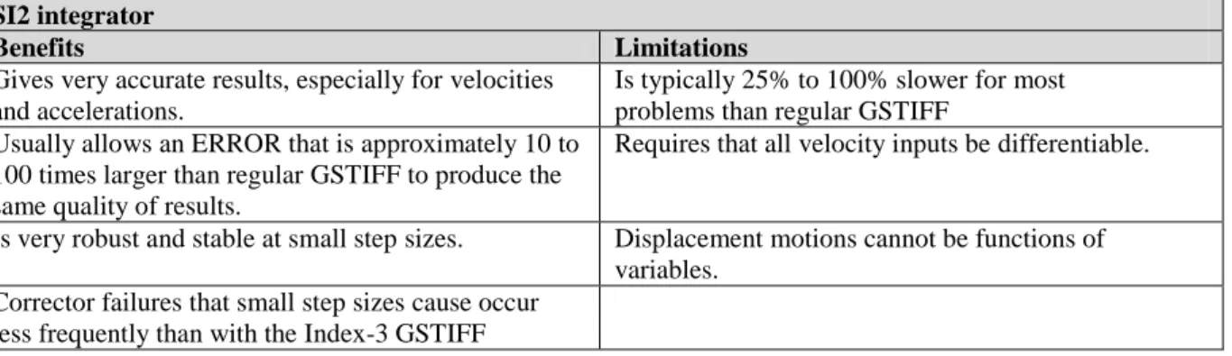
The SI2 integrator uses a different modelling technique than the standard integrators. The calculations become more time consuming but the result is given with higher accuracy. A recommended approach is to use the standard integrator for most problems and when high accuracies are required the SI2 can be used as comparison.
SI2 integrator
Benefits Limitations
Gives very accurate results, especially for velocities and accelerations.
Is typically 25% to 100% slower for most problems than regular GSTIFF
Usually allows an ERROR that is approximately 10 to 100 times larger than regular GSTIFF to produce the same quality of results.
Requires that all velocity inputs be differentiable.
Is very robust and stable at small step sizes. Displacement motions cannot be functions of variables.
Corrector failures that small step sizes cause occur less frequently than with the Index-3 GSTIFF Table 4 - SI2 integrator (Solidworks, 2005)
8.1.3 Joints and Constraints
To create a mechanical system based on a Solidworks assembly, CosmosMotion uses a number of joints and constraints to restrict the motion of the different parts and to connect them to each other. The joints can be mapped automatically from the mates created to set up the assembly in Solidworks but this can lead to an over constrained system in CosmosMotion. Mates are often created to fix the parts in all directions, but it can be useful to utilize the automatic mapping system if the Solidworks mates have been created with caution.
The joints and constraints created in CosmosMotion do not come into play until the model is sent to the ADAMS Solver, but Solidworks mates effect the way it is possible to move and rotate components in the assembly. By creating the mates in a way that it is possible to move
CosmosMotion Simulation
30
the mechanism in the same way that it is supposed to move in real life, the transition between Solidworks and CosmosMotion can be smooth.
In order to get the system to move displacement, motion or acceleration can be added to any joint.
8.2 Problem statement
The basic motion of the clinch unit is simple plane motion. The difficulties lie in the short time span and the contact conditions present, which require a small time step and narrow tolerances in the numerical solver which increase the solution time.
The primary goal of the motion simulation is to map the position and velocity of the clinch unit and to calculate the contact force between the linear guides and the clinch housing wall. A number of simulations where also performed to test the functionality of the program. This was done by creating different models of the scissors and cam mechanism, the locking plate and the entire clinch unit.
8.3 Modeling
The different models (Figure 20) where created on the crawl-walk-run approach, i.e. small parts of the model was simulated and checked before they where put together to a large simulation. For the final simulations two different setups was used: one simplified model corresponding to the analytical model, without any locking plate and one model including the locking plate. Just as for the analytical model the influence of the scissors cam mechanism was assumed to be small and was therefore not included.
In the process of learning the program the function of the scissors cam mechanism was simulated with good results, but no comparison was made with real life measured data.
The models included several 3D contact conditions e.g. between the linear guides and lifter. The position of the locking plate was only secured using contact constraints. Contact was modelled between the plate and the locking shaft, the cover plate and the middle plate. Also the impact between the clinch unit and the clinch housing
was modelled using 3D contact between the linear guides and housing wall.
The impact stiffness between the housing wall and linear guides where calculated using FEA. A detailed description of the analysis can be found in the chapter “FE-model”. It was put in to the 3D contact condition as a linear spring with no damping.
CosmosMotion Simulation
31
The position of the clinch unit and lifter was secured by creating distance mates in
Solidworks, which was then suppressed before creating the joints in CosmosMotion. This was made to ensure that the mates would not interfere with the automatic constrain mapping.
8.4 Results
Figure 21 - Clinch velocity and impact force
Data was saved mapping the velocity of the clinch unit, the position of the center of mass of the clinch unit and the impact force between the linear guides and clinch housing wall (Figure 21). It shows that the lifter compresses one of the lifter springs to its maximum and thereby hits the locking plate. This gives the clinch unit a sharp acceleration in the beginning. It then starts to move away from the lifter because of the force from the springs and at the point of impact the velocity has reached 2 m/s, while the lifters velocity stays around 0.75 m/s during the entire motion.
The impact between the clinch housing wall and linear guides generated a force of 250N, based on an impact stiffness of 300 N/mm. This force was used to calculate the stresses in the housing, which can be viewed in chapter “FE-model”.
Result comparison
32
9 Result comparison
9.1 Analytical and simplified CosmosMotion solution
The position and velocity of the clinch unit and the value of the impact force calculated in Part I of the analytical model was compared with the results from the simplified
CosmosMotion. This was done to test the ability to simulate short time spans in CosmosMotion.
Figure 22 - Comparison Clinch position and velocity
The result (Figure 22) shows that there is a very small difference between the position and velocity calculation. Calculating the impact force (Figure 23), the analytical solution gives a higher force though the same impact stiffness has been used.
To further test the solver in CosmosMotion, a comparison was made between the GStiff and SI2 GStiff solver. The two results align so closely that they can’t be distinguished in the comparison plots. This is because the tolerances of the simulation was already very small when calculating with the GStiff solver to capture the influence of the contact constraints, so that when switching to the SI2 solver there was not that much room for further refinements. If booth solvers were run with standard settings, the difference would have been more visible. In some settings using the standard solver the impact was missing completely because of the
short time span. This demonstrates the importance of trying different settings until the results become consistent.
Result comparison
33
9.2 CosmosMotion solution and test values
Figure 24 - Comparison CosmosMotion and test values
The plot of the clinch velocity shows that the simulation in CosmosMotion gives a solution similar to the numerical data approximation of the velocity based on the position data from the clinch position test (Figure 24). The general shapes of the curves are the same, showing a big acceleration at the very beginning, a result of the lifter hitting the locking plate. This collision gives the clinch unit a velocity of approximately 700 mm/s. After the collision the unit starts to move away from the lifter because of the force from the lifter springs.
The big difference is that the acceleration is much higher in the CosmosMotion model, probably because the lack of friction between the linear guides shafts and the fact that the scissor cam mechanism has been removed. Another source of error is the influence of the locking plate. It is possible that CosmosMotion can’t model the contact between the plate and shaft in a proper way. In real life it should slide along the shaft, causing the whole clinch unit to slow down. But in simulations its behaviour has been more chaotic, either it locks on to the locking shaft during the motion, resulting in a complete stop, or it doesn’t affect the motion at all, as shown above.
A third reason for the differences in velocity could be the characteristics of the lifter springs. At Isaberg Rapid it has been some quality problems in securing the right and consistent properties of the springs which leads to that the springs mounted in the stapler performing the clinch position test could be weaker than the ones added in the model. There is also the concern that the springs in the mathematical model are perfectly linear, a property that a real spring lacks.
Because of the greater acceleration, the clinch unit in the CosmosMotion simulation reaches the housing wall sooner and has a higher final velocity than the one measured.
FE-model
34
10 FE-model
An FE analysis was performed in order to calculate the contact stiffness between the clinch unit and the clinch housing and the stiffness of the housing during the clinching procedure, to be used in both the analytical and CosmosMotion models. The models was also used when calculating the impact and clinching stresses. Two static models where created in
CosmosWorks Designer using cad files of the clinch housing, the two shafts and two linear guides.
10.1
Background
Instead of formulating a complex analytical mathematical model in solid mechanics using beam theory, a problem can be solved using the FE-method. It is based on the theory that the geometry of interest is simplified into a mesh of elements with a simple mathematical
formulation. The points where the elements are connected to form the mesh are called nodes. “The extent of the approximations made in the model’s geometry, material behaviour,
boundary conditions, and loading determines how well the numerical simulation matches the physical problem.” (ABAQUS, 2006)
10.1.1 FE formulation
The FE method can be described in seven steps (Becker, 2004): 1. Define the element and the shape function
2. Satisfy the material law
3. Derive the element stiffness matrix ke a. Direct equilibrium approach b. Energy method (more general)
4. Assemble all ke to the global stiffness matrix K 5. Apply boundary conditions
a. Displacement conditions b. Force conditions
6. Solve the global equation system F = K u
7. Compute other variables (stresses, strains, from the displacement)
In practise, when using CosmosWorks, the program takes care of most of the steps but there are some choices which have to be made by the user:
What type of analysis?
The choice of a linear or non-linear analysis will affect the way the material properties are handled and how the equation systems are solved.
What kind of element is to be used?
FE programs often offer a number of different element types for the user to choose from. They are already defined and the element stiffness matrix has been derived.
FE-model
35 How should the mesh be created?
The solution of a FE calculation is very mush dependent on the mesh. The denser the mesh, the closer you get to the exact solution, though the element type is also a factor. When using a complex element formulation the mesh can be made less dense. There are two main ways of improving the accuracy of the solution: increase the mesh density or increase the polynomial order of the element formulation.
How to interpret real life conditions?
A FE analysis is always a simplified version of the real problem. Boundary conditions and restraints have to be created to correspond to conditions such as weldments, bolt connectors and interactions with part which has been excluded from the analysis. If the boundary conditions are modelled incorrect the solution will be invalid, regardless of mesh density, element types and solver accuracy.
10.1.2 Elements
There are two main types of element in solid mechanics: continuum and structural elements. The main difference between the element types is that the nodes of continuum elements only have its displacement as a degree of freedom, while structural elements have booth
displacement and rotation. As far as the FE-method goes the elements can be constructed to be used in virtually any kind of problem, such as electrical grid, thermal flow, water flow and so on. Then the degrees of freedom of course will differ.
Continuum elements o Truss o 2D plane stress o 2D plane strain o Axisymmetric o 3D Structural elements o Beam o Plate o Shell
CosmosWorks offers four different types of elements (Table 5): first and second order 3D tetrahedral elements and first and second order triangular shell elements.
First order 3D Second order 3D First order shell Second order shell
FE-model
36
Cad geometry Solid element mesh
Figure 25 - Solid mesh (Solidworks, 2006)
Figure 25 shows a mesh of second order elements which can adapt smoothly to the curvature of the geometry.
Cad geometry Shell mesh
Figure 26 - Shell mesh (Solidworks, 2006)
When using shell elements (Figure 26) the thickness of the structure will not be shown, it is only stated in the element properties. The shell elements can be very effective when looking at sheet metal parts, because the element count will be much lower than for a 3D mesh which will often need a number of elements through the thickness of the plate to give accurate results.
10.1.3 CosmosWorks solvers
CosmosWorks 2006 includes three different solvers: Direct Sparse, FFE and FFEPlus.
Generally the program automatically chooses an adequate solver based on the problem. But it can also be chosen manually in the simulation set up.
FE-model
37
The following factors could be taken into consideration when choosing the proper solver (Solidworks, 2006):
Size of the problem. In general, FFEPlus is faster in solving problems with degrees of freedom (DOF) over 100,000. It becomes more efficient as the problem gets larger. Computer resources. The direct sparse solver in particular becomes faster with more
memory available on your computer.
Analysis options. For example, the in plane effect, soft spring, and inertial relief options are not available if you choose the FFE solver.
Element type. For example, contact problems and thick shell formulation are not supported by the FFE solver. In such cases, the program switches automatically to FFEPlus or the Direct Sparse solver.
Material properties. When the module of elasticity of the materials used in a model are very different (like Steel and Nylon), then iterative solvers are less accurate than direct methods. The direct solver is recommended in such cases.
10.1.4 CosmosWorks mesh creation
Basic mesh creation in CosmosWorks only requires one input by the user: the global mesh size. This size decides how big the element is allowed to be, the smaller value, the finer mesh. CosmosWorks estimates a default value for the mesh, taking the model volume and surface area into consideration. The value is suitable for structural analysis of the behaviour of a model, but stress calculation of often require a finer mesh.
Instead of decreasing the global mesh size which can heavily increase the solution time, the mesh can be locally refined in places of interest. A key note in mesh creation is that it should not be finer than necessary to give an accurate result.
The function Automatic Transition (Figure 27) in CosmosWorks automatically refines the
mesh around fillets, holes and other details but tries to keep the overall mesh size close to the assigned global value.
Automatic transition off Automatic transition on
Figure 27 - Automatic transition (Solidworks, 2006)
Using Mesh Control the user can choose any point, face, or component for which another element size should be used. It is a powerful tool for refining the mesh in critical areas while keeping the model size low.
FE-model
38
10.2
Clinching stress and stiffness calculation
The goal of the locking plate analysis was to calculate the stress in the clinch housing. The displacement created by the clinchers is transferred to the housing by the locking shaft and therefore a distributed force was applied representing the contact area between housing and shaft.
To be able to apply a preload in the analytical model the average stiffness of the structure also had to be calculated. This was done by applying a small force at the contact area between the clinch housing and locking shaft and then calculating the stiffness based on
Force/Displacement.
10.2.1 Element type and solver
The element used in the simulation was the second order solid element 10 node tetrahedral elements because of the accuracy required. The elements are referred by Cosmos as high quality mesh (first order elements – draft quality). 3D elements are used instead of shell elements because of the fact that the inner radius of the housing wall is much smaller than the outer radius. This relationship is difficult to capture with shell elements.
Because of the rather simple nature of the simulation, a convergence test was preformed to establish a sufficient mesh density. The simulation was preformed six times with different mesh settings, with and without local refinements (mesh control) and automatic transition. When turned on, the mesh control was applied on the inner and outer bend, as well as at the sides of the housing wall.
10.2.2 Model
The wall of the clinch housing featured a sharp edge as an “inner radius” which would lead to a stress singularity when performing the simulation. Instead a small fillet with the radius of 0.2 mm was added.
A distributed force was applied at the contact area between the locking shaft and clinch housing wall. This was accomplished in SolidWorks by projecting the edge of the shaft onto the wall and using the split line command. The clinch housing was then constrained based on the information mentioned in section “Connectors”.
The material used in the model was standard alloy steel with an elastic modulus of 210 GPa and Poisson’s ratio of 0.28. For the simulations in CosmosWorks no plasticity or hardening is added to the model, only the elastic behaviour is taken into consideration. The yield limit of the material is estimated to 380 MPa, which is common for a standard alloy steel.
FE-model
39
10.2.3 Stiffness calculation and convergence study
10.2.3.1 Mesh
Coarse Fine Very Fine
Figure 28 – Mesh refinements
Six different mesh settings was used (Figure 28), ranging from a coarse mesh (10 000 elements) to a very fine mesh (300 000 elements). A detailed description of the different settings can be seen in Attachment V.
Figure 29 - Convergence study
The calculated displacement of the housing wall can be seen converging with increased mesh density (Figure 29).
FE-model
40 10.2.3.2 Results
The displacement of the housing wall is 0.02001 mm when subjected to a distributed force of 10N (Figure 30). The averaged stiffness is calculated by F= k δ, which gives a k = 500N/mm.
Figure 30 - Displacement
The displacement is measured at the outside top of the housing wall (Figure 31). The plot
shows the maximum displacement.
FE-model
41
10.2.4 Stress calculation
10.2.4.1 Results
The only difference between the stress calculation and the stiffness calculation was the size of the load applied, the same mesh setting and solver was used. Instead of 10N in the previous case, 190N was applied, corresponding to a displacement 0.38mm in the housing wall.
Figure 33 - Stress results
The maximum stress (Figure 33) of 400 MPa appears at the inner radius of the housing wall (Figure 32). By using the linear relationship between force and stress, the maximum stress at different loads can be easily derived without rerunning the simulation.
Table 6 shows the maximum stress at the different loads calculated from the analytical model of the plate. F σmax δmax 190 N 408.1 MPa 0.38 mm 623 N 1338 MPa 1.246 mm 210 N 451 MPa 0.42 mm 690 N 1482 MPa 1.38 mm
Table 6 Stress and displacement results at different loads
In all four cases the maximum stress is close or high above the yield limit of the material, which is estimated to 380 MPa. The reason for the high stresses is the small radius. It is reasonable to assume that during the load cycle plastic deformation change the behaviour of the wall, reducing the maximum stress, but it still remains at dangerously high levels with respect to fatigue. This can be motivated by that it is at the inner radius fracture eventually occur in real life.
Further discussion and a study of the inner radius can be found in the following sections.
Figure 32 - Location of maximum stress