EVERSAFE
Everyday Safety for Electric Vehicles
Risk management approach
Deliverable No. 4.1
Workpackage No. 4
Workpackage Title Safety requirements and analysis
Editor Dr. Ivo Häring/haering@emi.fhg.de
Authors Bülent Kanat/EMI
Status (F: Final; RC: Review Copy: D: draft): F
Reviewed and approved for submission
(name and date) Rob Thomson(VTI), 24/01/2013
An ERA-Net collaborative project. Work programme: Electromobility +
Document History Table
VersionNo. Date Details
1.0 28.09.2012 First Release by EMI 1.1 13.01.2013 Review by WP leader 1.2 15.01.2013 Approved version from EMI
1.3 21.01.2013 Reviewed and approved by WP leader – Robert Thomson 1.4 24.01.2013 Reviewed and approved by project coordinator
EXECUTIVE SUMMARY
The EVERSAFE project has the challenge to identify potential safety issues for vehicles which have had limited commercial sales, and thereby, limited field data to document safety and reliability issues in terms of event details and frequency. ISO 26262 is a new branch specific standard for functional safety of automotive electrical/ electronic/ programmable electronic (E/E/PE) systems carrying out a safety function. The standard aims to identify the potential hazards caused by malfunctions of E/E/PE systems, to assess their risks and to reduce the risks demonstrably to an acceptable level by taking the appropriate countermeasures. As safety investigations are part of EVERSAFE project, ISO 26262 is a relevant approach for this project. In addition, the determination of risks that must be further reduced is covered by the safety life cycle of ISO 26262, independent of their reduction by E/E/PE safety functions or not.
The EVERSAFE project is planning a workshop to identify the main safety risks that should be addressed in the project. The main goal of this report is to review the ISO 26262 and to identify the safety life cycle phases that are covered by project activities for active safety investigation of EVERSAFE. This framework will be a basis for the workshop. Of particular relevance is the Automotive Safety Integrity Level (ASIL) system that provides a system for identifying the hazards, their exposure (expected frequency) to the vehicle occupants, controllability by the driver, and the resulting severity. For this purpose, the scope, structure and content of ISO 26262 are described in detail. In particular, safety life cycle phases, their requirements and analysis methods to fulfil them are presented.
LIST OF ABBREVIATIONS
AC Alternating Current
ASIL Automotive Safety Integrity Level ABS Anti-lock Braking System
BEV Battery-Electric Vehicle
BBW Brake-by-Wire
CBCM Central Brake Control Management Module CI Communication Interface
DC Direct current
EBM Electromechanical Brake Module ECU Electronic Control Unit
E/E/PE Electrical/ Electronic/ Programmable Electronic ESP Electronic Stability Program
ESS Energy Storage System EV Electric Vehicle
FEV Fuel-Cell Vehicle
FMEA Failure Mode and Effects Analysis FTA Fault Tree Analysis
HA Hazard Analysis
HEV Hybrid Electric Vehicle
HV High Voltage
HL Hazard List
IEC International Electrotechnical Commission IFAC International Federation of Automatic Control ISO International Organization for Standardization MDB Moving Deformable Barrier
ODB Offset Deformable Barrier
O&SHA Operating and Support Hazard Analysis PHA Preliminary Hazard Analysis
SHA System Hazard Analysis SOP Start of Production
SSHA Subsystem Hazard Analysis
UN-ECE United Nations – Economic Commission for Europe VSS Vehicle Speed Sensor
Table of Contents
EXECUTIVE SUMMARY ... iii
List of abbreviations ... iv
1. Introduction ... 1
2. OVERVIEW OF CURRENT STANDARDS FOR VEHICLE SAFETY ... 2
3. ISO 26262 ... 4
3.1 Scope ... 4
3.2 Structure and content ... 4
3.3 ISO 26262 from the viewpoint of EVERSAFE ... 6
4. PARTIAL EXEMPLARY APPLICATION OF ISO 26262 ON A BRAKE-BY-WIRE SYSTEM ... 9
4.1 System definition ... 9
4.2 Preliminary Hazard Analysis and determination of ASIL ... 10
4.3 Functional Safety Concept ... 11
5. CONCLUSIONS ... 12
List of Tables
Table 2.1: Current activities for standardization in the area of EVs [1]. ... 2
Table 2.2: UN-ECE regulations [] and identified links to EVERSAFE. ... 3
Table 3.1: Rating matrix for ASIL determination []... 5
Table 4.1 Snippet of hazard list for BBW system. ... 10
Table 4.2: Snippet of preliminary hazard analysis for BBW system []. ... 10
List of Figures
Figure 3.1 Safety life cycle according to ISO 26262 [2]. ... 4Figure 3.2: Alternative approach for functional safety management for project EVERSAFE tailoring the safety life cycle of ISO 26262. ... 7
1.
INTRODUCTION
The main objective of EVERSAFE is to facilitate integration of electrical vehicles (EV) into European vehicle traffic. The basic prerequisite for the successful integration is gaining customer acceptance which involves a brand identity with appropriate features for targeting markets. Thereby, a strong market value of European vehicle manufacturers can be achieved worldwide.
The customer acceptance increases by maximizing the EV safety granted to persons in the event of an accident. Therefore, a significant development focus is accident research, which serves as a guide for technical safety innovations. The expertise of accident researches is used for further development activities related to active and passive vehicle safety. Achieving vehicle safety is a process that requires a precise plan and structure that are specified in the corresponding standards. The structured approach guided by standards allows reducing the mishap potential of the system under development to a minimal level. The standards support also fields of innovations like electro mobility and promote research results to the marketable systems.
In this report, after a short overview of relevant standardization activities regarding electro vehicle, a detailed description of ISO 26262 follows, which is well established in the automotive industry. The standard is presented and its important aspects, such as the safety life cycle and its requirements, are described in detail. Furthermore, the application of ISO 26262 is clarified with the aid of an example.
2.
OVERVIEW OF CURRENT STANDARDS FOR VEHICLE SAFETY
The challenge of standardization in the area of the EV lies in the goal-oriented coordination and integration of various activities of different branches of industry. A domain-specific separation of standards between electro-technology, energy and automobile technology is difficult for EVs. The integration of these domains leads to new interfaces that need a clear overarching viewpoint. There are a large number of standards and regulations already used in automotive industry. However, the branch specific standards, such as safety of high voltage (HV) components during and after crash, have to be refined [1]. Table 2.1 gives an overview of the current branch standards for the electrical safety in EVs.Table 2.1: Current activities for standardization in the area of EVs [1].
Identification Scope Status
ISO 6469
Specifies safety requirements for battery-electric vehicles (BEVs), fuel-cell vehicles (FCVs) and hybrid electric vehicles (HEVs) regarding the on-board rechargeable energy storage system, the protection of persons against electric shock and against electrical circuits after crash.
Published1
ISO 23273
Specifies the essential requirements for the functional safety of FCVs with respect to hazards to persons and the
environment inside and outside of the vehicle caused by the fuel cell power system, the hydrogen and electric shock.
First draft international standard2
IEC 60364-4-41
Specifies essential requirements regarding protection against electric shock, including basic protection (protection against direct contact) and fault protection (protection against indirect contact) of persons and livestock.
International standard
IEC 62660-2 Specifies test procedures to observe the reliability and abuse behaviour of secondary lithium-ion cells used for propulsion of BEVs and HEVs.
International standard
ISO 12405
Specifies test procedures for lithium-ion battery packs and systems of electrically propelled road vehicles to determine the essential characteristics on performance, reliability, safety and abuse.
International standard3
IEC 61508
Specifies the pertinent requirements for E/E/PE systems used in safety functions. It covers all applications where system malfunctions have a decisive effect on the safety of the user, the environment and the equipment concerned.
International standard ISO 26262 Describes a functional safety standard that is an adaptation
of the IEC 61508 for the automotive industry.
International
In Europe, legislative standards are prescribed for automobiles sold in the EU. There are both EC directives and UN-ECE regulations that are applicable. As the EC directives refer to UN-ECE regulations when it comes to technical performance criteria, only the UN-ECE regulations are provided in Table 2.2. The WP in EVERSAFE relevant for each standard is indicated.
1 Part 4 is under development.
2 A withdrawn ballot was initiated for Part 1 and 3. 3 Part 3 is under development
Table 2.2: UN-ECE regulations [2] and identified links to EVERSAFE.
Identification Addresses Relevance for EVERSAFE and applicable WP
Reg. 10
Approval of Vehicles with regard to electromagnetic compatibility
Addresses basic environmental requirements for electrical systems (WP2)
Reg. 13 Braking on vehicles of categories M, N and O.
Covers baking performance and functions in vehicles (WP2)
Reg. 32 Rear-end collision Identifies crash and performance requirements in rear end crashes of 35 km/h (WP3)
Reg. 34 Prevention of fire risks
Describes a set of component and whole vehicle tests and fire prevention requirements. Connect to R32, R94, and R95 (WP3)
Reg. 42 Front and rear protection devices of vehicles
Describes low speed tests (2.5-4 km/h) for the vehicle to address vehicle performance and occupant safety during and after the test (WP3)
Reg. 94 Protection of occupants against frontal collision
Frontal impact test (56 km/h and 40% overlap into ODB) to test occupant safety. Also covers structural issues like steering wheel displacement and fluid leakage (battery electrolyte /fuel) (WP3). Revisions to R94 will address electrical safety (WP3).
Reg. 95 - Protection of occupants against lateral collision
Side impact test (50 km/h with 1500 kg MDB 40% overlap) to test the occupant safety. Also covers structural issues like steering wheel displacement and fluid leakage (battery electrolyte /fuel) (WP3). Revisions to R95 will address electrical safety (WP3).
Reg.100 -
Battery electric vehicles with regard to specific requirements for
construction and functional safety
Construction and functional requirements for vehicles with electric drivetrain components. Overlaps with some ISO standards in Table 2.1. (WP2, WP3)
Reg.121 - Identification of controls, tell-tales and indicators
Requirements for the types of indicators and signals that feedback vehicle information to the driver (WP2) The standards listed in Table 2.1 and Table 2.2 can be used as guideline for the investigations of EVERSAFE. A detailed review of all listed standards is not possible within the given resources of Task 4.1. Therefore, we focus on the standard ISO 26262 which is well-established in the automotive industry and regulates the functional safety of the E/E/PE systems, in particular during development.
Due to an increasing market share of the high-voltage components with a hazard potential, the crash behaviour of EVs has to be brought to the latest state of technology. For this purpose, ISO 26262 can be used as a guideline which clearly defines the requirements for safety-related components and shows possible approaches to fulfill these requirements. In the following sections, the risk assessment according to ISO 26262 will be described in detail. The main idea is that up to the point where the developers decide how to mitigate risks, the risk determination of ISO 26262 can be used independent of the passive or active countermeasures. Of course this approach must be applied iteratively.
3.
ISO 26262
ScopeISO 26262 is a new branch specific standard for functional safety of automotive E/E/PE systems carrying out a safety function in “series production passenger cars” with a maximum weight of 3500 kg. The main aim of this standard is to identify the potential hazards caused by malfunctions of E/E/PE systems and/or their interaction in order to assess their risks and to reduce the risks of the overall system demonstrably to an acceptable level by taking the appropriate countermeasures.
Structure and content
ISO 26262 consists of 10 parts that are ordered and structured corresponding to the safety life cycle, whose detailed description takes place in parts 3 to 7. Figure 3.1 illustrates the overall safety life cycle and its phases.
Figure 3.1 Safety life cycle according to ISO 26262 [2].
The safety life cycle is separated in 3 phases: concept phase, product development and after start of production (SOP). Generally, every phase consists of 3 sections: planning of the activities, performing of the activities, verification and validation of generated products.
The part 3 describes the concept phase. It starts with the item1 definition. Subsequently to this, hazard
and risk analyses should be performed. Corresponding to the results of these analyses safety-goals for all hazards are derived and assigned with an appropriate automotive safety integrity level (ASIL).
ASIL is a measure for safety-relevant malfunctions. It is divided in four levels from A to D, where ASIL A requires the lowest safety measures and ASIL D the highest one.
The ASIL is defined by the following parameters:
Exposure (E): The probability of exposure of each operational situation in which malfunctions are safety relevant. The probability of exposure shall be estimated and assigned to one of the probability classes E1 to E4.
Controllability (C): The probability that the driver or other endangered persons are able to control the hazardous event and are able to avoid the specific harm. The controllability shall be estimated and assigned to one of the controllability classes C1 to C3.
Severity (S): The severity of potential harm. The severity shall be estimated and assigned to one of the severity classes S1 to S3.
The classification of severity, controllability and exposure is explained with examples in ISO/DIS 26262-3. After the estimation of the abovementioned parameters, the ASIL rating for each hazardous event is determined by using the rating matrix of Table 3.1
Table 3.1: Rating matrix for ASIL determination [3].
As Table 3.1 shows, the malfunctions that are not classified safety-relevant are assigned with QM (Quality management). The class QM denotes no requirement in accordance with ISO 26262.The concept phase is concluded with functional safety concepts that specify – corresponding to the determined ASILs - the basic safety mechanisms and safety measures in the form functional safety
Part 4 deals with the development phase, where the functional safety requirements for the whole system are derived from the safety concepts [4]. In Parts 5 and 6, the derived requirements are refined and specified for hardware and software [5,6,].
The safety requirements for production, operating, service, decommissioning are specified in part 7. The other parts (1 and 8-10) of the ISO 26262 have an informative character and support the application of the standard.
ISO 26262 from the viewpoint of EVERSAFE
The focus of EVERSAFE is on crash-compatibility, battery safety, vehicle stability and the driver response to the faults during a risk situation. Within EVERSAFE the critical risk situations are identified by computer simulations and crash experiments in order to refine the safety requirements for EVs. The critical components, such as energy storage systems (ESS), are tested under crash conditions. Recommendations are submitted for future vehicles that may increase the safety of passengers or endangered persons.
The functional safety is also involved in the aforementioned situations. As examples, EVERSAFE investigates the battery management system which controls actively all operations of the battery, and the electro stability program (ESP), which stabilizes the vehicle in the risk situations. In the light of these considerations, it is preferable to perform a risk assessment for the active safety systems according to ISO 26262.
The safety lifecycle is a process that is considered during planning, design and manufacturing of the safety-related systems. It is divided into many phases that are progressively structured and build on each other. During the course of the project EVERSAFE, no new system is developed. Therefore, a major challenge of EVERSAFE is to identify the appropriate safety lifecycle phases of ISO 26262 for the project activities and to (partially) fulfill the demanded requirements.
For this purpose, ISO 26262 allows the so-called tailoring of the safety lifecycle, i.e. to generate a project specific adaptation of the safety lifecycle. The standard distinguishes the following three types of tailoring:
The safety lifecycle is tailored because of a modification to an already existing item [3]:
In this case, an analysis shall be performed to identify the impact of the modifications to the system.
The safety lifecycle is tailored because of a proven in use argument [7]:
A proven-in-use argument can be applied to any type of product that is already released and in operation. In this case, the fulfillment of the requirements has to be proven for the respective item, which is already in use and has satisfactory field data for the analysis by comparison with target values given in ISO 26262 – 14.4.5.
The safety lifecycle is tailored, in non-project specific manner [8]:
The tailoring can be carried out independent of the project, that means an activity or task can be performed in a different phase, in an added phase or sub phase. Furthermore, ISO allows the combining or splitting of sub phases, activities or tasks.
The development or the modification of an already existing system does not take place during EVERSAFE. Also, prove-in-use arguments cannot be applied because there is no single item within the EVERSAFE consortium with sufficient field data about crash situations of EVs.
The main objective of EVERSAVE is to analyze the crash behaviour of already existing systems (first generation EVs) in order to identify their critical weaknesses that also lead to requirements for second generation EVs. In this regard, the project activities can be considered as verification process of already existing safety concepts and assigned to the concept phase of the safety life cycle.
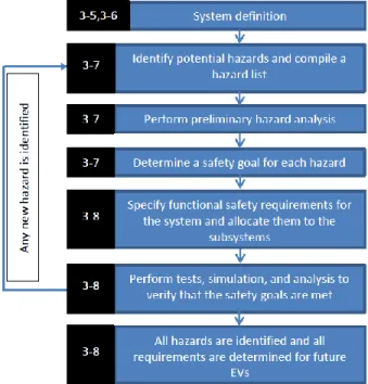
Figure 3.2: Alternative approach for functional safety management for project EVERSAFE tailoring the safety life cycle of ISO 26262.
Following the tailored part of the safety life cycle of ISO 26262 of Figure 3.2,
First the respective system is defined. This comprises the definition of its functionality, of the system boundaries, possible system safety states and interactions between functionalities. See section 4.1 for an example.
Second, the potential hazards are identified and listed. For this step, the already performed safety analyses results from previously projects can be used. Here we recommend using a hazard list (HL).
Third, the identified hazards are analyzed. There are several different hazard analysis types depending on the developments phases and available system information. As examples, preliminary hazard analysis (PHA), system hazard analysis (SHA), subsystem hazard analysis and operating and support hazard analysis (O&SHA) could be mentioned. The aim of each hazard analysis type is to identify hazards for a particular design phase in the system development life cycle. For detailed information about different types of HA see [9]. Typically, PHA is performed in an earlier development phase (e.g. concept phase) with less detailed design information
Fourth, the safety goals are determined. Here we recommend using a risk matrix. See Table 3.1.
Fifth, based on the safety goals, the functional safety requirements are specified and allocated to the subsystems.
Sixth, using computer simulations, crash tests and system analysis methods (e.g. FMEA, FTA) it can be verified, if the system meets the demanded requirements.
During the investigations of steps 3-5 to 3-8, new hazards are identified which may violate the safety goals. They should be recorded in the hazard list and the above steps are repeated beginning with the hazard analysis. This process should be performed until all requirements are determined that are compliant with the safety goals. This allows EVERSAFE to determine which risks are completely mitigated by the measures of EVERSAFE and which need further treatment and to which degree.
In the following sections based on an exemplary active safety system, a PHA is performed and its safety goal as well as safety requirements are determined. Note that the used system architecture, derived ASIL and requirements may not necessarily reflect reality. They only serve for better comprehension.
According to ISO 26262, the verification can be applied in all lifecycle phases, and ensures that the work products are correct, complete and consistent as well as fulfilling the requirements of the standard [7]. Taking these aspects into consideration, the following approach is a possible approach for functional safety management during the project EVERSAFE.
4.
PARTIAL EXEMPLARY APPLICATION OF ISO 26262 ON A
BRAKE-BY-WIRE SYSTEM
System definition
In automotive industry, the term brake-by-wire (BBW) refers to the concept where a conventional hydraulic or electro-hydraulic braking system is replaced by a fully electric/electronic system. A BBW system consists of electro-mechanical actuators, the control unit, sensors and the communication network. Any such sub-system is counted to the active safety systems and performs safety functions. Therefore BBW systems have to comply with the requirements of ISO 26262 and UN-ECE Reg. 13 during the whole product lifecycle. Figure 4.1 illustrates the simplified functional concept of a BBW system.
Figure 4.1: Block diagram of a BBW system [10]
A typical BBW system consists of four electromechanical brake (EMB) modules, a communication network, a brake pedal module and a central brake control management module (CBCM). The main components of the brake pedal module are multiple sensors, a processor and a voter. Each EMB consists of a motor-driven actuator and associated control units (ECU) as well as a communication interface (CI). All wheels are equipped with wheel speed sensors (WSS). Furthermore, an additional vehicle speed sensor (VSS) delivers the current speed information of the vehicle.
Brake information such as the force and speed of the brake, is extracted from the brake pedal module by multiple sensors integrated in the pedal box. The CBCM receives signals of the pedal module, the steering angle, the vehicle velocity, the wheel rotation speeds and information related to vehicle motion and safety. With this information the brake force of the actuator is calculated and sent to EMBs which perform the braking. During braking, the WSSs give feedback on the wheel status to EMBs which monitor the operations of the components, detect failure, and deal with them [10].
Preliminary Hazard Analysis and determination of ASIL
After system definition, a PHA is performed in order to determine the safety goal, i.e. the ASIL. This analysis technique is used for the systematic identification of hazards, their associated causal factors, effects, level of Risk (ASIL) and mitigating design measures of the systems.
Prior to the PHA, a hazard list (HL) is generally compiled, in which all identified hazards, their source and possible consequences are listed and updated when a new hazard was identified. Basic design knowledge, information about known hazardous elements and mishap lessons from similar systems are helpful for compiling of a HL. An example of a hazard list for the sample system is given in Table 4.1
Table 4.1 Snippet of hazard list for BBW system.
System: BWB Hazard List Analyst: John Sample
Date: 05.05.2012 Hazard ID Operation
mode
Hazard Title Hazard description
Mishap potential
Potential cause for failure 1 Driving with high speed Total loss of braking Vehicle does not decelerate at all when driver applies brakes Loss of brake functions leads to loss of vehicle deceleration
Failures in the brake system controller, sensors, actuators that are undetected or unmitigated 2 Driving with high speed Unintended braking One of EMBs performs constant brake torque Unintended braking of one of an EMB leads to vehicle instability Failure in an EMB that is undetected or unmitigated
The identified hazards from the HL or possibly previously unrecognized hazards are then analyzed by the PHA. The PHA is typically carried out by using a specialized worksheet. Table 4.1 presents a recommended worksheet used for an exemplarily performed PHA based on the BBW system.
Table 4.2: Snippet of preliminary hazard analysis for BBW system [11].
As seen in
Table 4.2, identified hazards, their description, consequences and potential causes with an identification number are entered in the worksheet. For each hazard, an ASIL level and an appropriate functional concept in form of requirement are defined.
In this example, the hazard “total loss of braking” is analyzed and assigned with ASIL D. For the determination of the ASIL, first the severity class is estimated. A totally missing brake can have fatal consequences, so to the severity should be assigned the highest class S3. Naturally, this hazard may not always lead to serious harm, but in the realization of the PHA, the analyst should assume the worst case scenario.
In the next step, an estimation of the exposure probability shall be made, or in other words, the question has to be clarified how often situations occur in which “total loss of braking” is relevant. Since braking is one of the most often used processes during driving, the total missing of the braking is in almost 100 % of all situations relevant. Hence its exposure is assigned the highest class “E4”.
As the last step in the risk assessment, the controllability class is estimated that for the case when the brake system fails. In a traffic calmed zone or at the starting of the motor, a malfunction of the system may be well controlled. But as aforementioned, the analyst should consider the worst case scenario (e.g. total loss of braking on a highway with high speed) so that controllability is estimated as “C3”. Based on these results, the safety rating ASIL ”D” is determined by means of the ASIL matrix given in Table 3.1.
In this manner, the ASIL for other hazards, such as unintended braking process, insufficient braking power and stability problems of vehicles due to malfunctions of the EMBs, can be analyzed. Furthermore, the hazard analysis, risk assessment and the safety goal have to be reviewed to verify the completeness and correctness [3].
Functional Safety Concept
After the ASIL determination, each functional safety requirement shall be specified considering the following information [3]:
Operating modes
Fault tolerant time interval
Safe states
Emergency operational interval
Functional redundancies
Warning and degradation
In this example, a functional safety requirement for the considered hazard is defined, which implies that the loss of braking shall be avoided by detecting and mitigating the causes before it occurs. Furthermore, as a technical safety requirement, it is suggested that fault redundancy shall be built in the BBW system in order to avoid this hazard.
In the next step, the specified technical safety requirements are allocated to subsystems and they shall be evaluated to determine their effectiveness by simulations and tests. These analyses can generate additional conditions, causes, faults, failures that lead to violations of the safety goal [3,7]. If this case occurs, they shall be entered into the hazard list and the above-described process steps shall be performed again. In this way new functional requirements will be determined, which comply with the
5.
CONCLUSIONS
The standard ISO 26262 addresses functional safety of systems with safety-critical E/E/PE systems. It defines a safety life cycle and gives requirements for the development processes of E/E/PE systems in the concept and product development phases as well as after start of production (SOP). In the concept phase, first the system under investigation is defined, and subsequently a preliminary hazard analysis (PHA) is performed in order to derive the safety goals and appropriate functional safety concepts. The determined functional safety concepts are refined to technical safety concepts in the product
development phase. In this phase, requirements for development of hardware and software are derived from the technical safety concepts. The SOP phase contains mainly requirements for production,
operation and service. Each safety life cycle phase requires planning, performing, verification and validation.
Within the scope of EVERSAFE, aspects of active and passive safety will be investigated. Since ISO 26262 addresses functional safety of E/E/PE systems, the standard cannot be applied for designing or
improving passive safety systems. However, its approach can be applied to assess the achieved hazard mitigation through passive measures. This is also a requirement for the appropriate definition of the safety functions. HA can be also performed for passive safety system in order to determine system risk and thereby ascertain the significance of hazards so that design measures can be established to eliminate or mitigate the hazards. In this case, risk assessment and measures are performed according to respective standards and not to ISO 26262.
ISO 26262 can be applied to active safety systems, whose malfunctions and driver responses also belong to the subject of EVERSAFE. The aim is the identification of requirements for the design of future electric vehicles. For this purpose, the potential hazards caused by malfunctions of E/E/PE systems and/or their interactions can be identified and assessed regarding their risks. Subsequently, the functional safety requirements can be determined to reduce the risks demonstrably to an acceptable level. By computer simulations and crash tests, it can be verified whether the systems under investigation fulfill the specified requirements or not. The requirements, which are not yet met by the considered EV systems, will be identified and should be implemented in future EVs.
In terms of methods and their order, the following set of documentation and methods can be considered:
(1) Short and concise descriptions of EV (sub)system under consideration, see section4.1 for an example
(2) Hazard List (HL), e.g. according to the template of Table 4.1. (3) PHA, e.g. according to the template of
(4) Table 4.2
(5) Short and concise documentation of mitigation measures and their effectiveness for reference within the PHA.
6.
REFERENCES
1 NPE, Die deutsche Normungs-Roadmap, in Elektromobilität, S. Hölk, Editor 2012, Gemeinsame Geschäftsstelle Elektromobilität der Bundesregierung: Berlin.
2 UN-ECE Regulation webpage http://www.unece.org/trans/main/wp29/wp29regs.html
3 ISO/DIS 26262, Road vehicles – Functional safety – Part 3: Concept phase, 2009, International Organization for Standardization.
4 26262, I.D., Road vehicles – Functional safety – Part 4: Product development: system level, 2009, International Organization of Standardization.
5 ISO/DIS 26262, Road vehicles – Functional safety – Part 5: Product development: hardware level, 2009, International Organization for Standardization
6 ISO/DIS 26262, Road vehicles – Functional safety – Part 6: software level, 2009, International Organization for Standardization.
7 ISO/DIS 26262, Road vehicles – Functional safety – Part 8: Supporting processes, 2009, International Organization for Standardization.
8 ISO/DIS 26262, Road vehicles – Functional safety – Part 2: Managment of functional safety, 2009, International Organization for Standardization.
9 Ericson, C., Hazard Analysis Techniques for System Safety 2005, Virginia: Wiley.
10 Xiang W. , R.P.C., Zhao C., Mohammad S. , Auotomobile Brake-by-Wire Control System Design and Analysis. IEE Transactions on Vehicular Technology, 2008. 57: p. 138-145.
11 Sinha, P., Architectural design and reliability analysis of fail-operational brake-by-wire system from ISO 26262 perspectives. Reliability Engineering and System Safety, 2011. 96: p. 1349-1359.
![Table 2.1: Current activities for standardization in the area of EVs [1].](https://thumb-eu.123doks.com/thumbv2/5dokorg/4789178.128261/8.918.105.813.362.907/table-current-activities-standardization-area-evs.webp)
![Table 2.2: UN-ECE regulations [2] and identified links to EVERSAFE.](https://thumb-eu.123doks.com/thumbv2/5dokorg/4789178.128261/9.918.111.792.126.739/table-ece-regulations-identified-links-eversafe.webp)
![Figure 3.1 Safety life cycle according to ISO 26262 [2].](https://thumb-eu.123doks.com/thumbv2/5dokorg/4789178.128261/10.918.119.748.463.812/figure-safety-life-cycle-according-iso.webp)
![Table 3.1: Rating matrix for ASIL determination [3].](https://thumb-eu.123doks.com/thumbv2/5dokorg/4789178.128261/11.918.222.703.507.905/table-rating-matrix-for-asil-determination.webp)
![Figure 4.1: Block diagram of a BBW system [10]](https://thumb-eu.123doks.com/thumbv2/5dokorg/4789178.128261/15.918.133.789.368.682/figure-block-diagram-bbw.webp)
![Table 4.2: Snippet of preliminary hazard analysis for BBW system [11].](https://thumb-eu.123doks.com/thumbv2/5dokorg/4789178.128261/16.918.111.790.804.955/table-snippet-preliminary-hazard-analysis-bbw.webp)
