V¨
aster˚
as, Sweden
Thesis for the Degree of Master of Science in Software Engineering
-30.0 credits
ROBOREBECA: A NEW
FRAMEWORK TO DESIGN VERIFIED
ROS-BASED ROBOTIC PROGRAMS
Saeid Dehnavi
sdi18002@student.mdh.se
Examiner: Jan Carlson
M¨
alardalen University, V¨
aster˚
as, Sweden
Supervisors: Marjan Sirjani, Ali Sedaghatbaf
M¨
alardalen University, V¨
aster˚
as, Sweden
Company supervisor:
Acknowledgement
First I would like to thank my thesis advisors Prof. Marjan Sirjani and Dr. Ali Sedaghatbaf at the School Innovation, Design and Technology at Mlardalen University. The door to their office was always open whenever I ran into a trouble spot or had a question about my research or writing. They consistently allowed this thesis to be my own work, but steered me in the right the direction whenever he thought I needed it.
I would also like to thank my friends at IDT department who had a big role in keeping me full of energy by all the fun we had together: Mohammad, Hamid, Komeil, Zeynab, Neda, Ramon, Ali, Sima, Afshin, Lex, Bahare and Bahar.
Finally, I must express my very profound gratitude to my parents for providing me unfailing support and continuous encouragement throughout my years of study and through the process of researching and writing this thesis. This accomplishment would not have been possible without them.
Abstract
Robotic technology helps humans in different areas such as manufacturing, health care and educa-tion. Due to the ubiquitous revolution, today’s focus is on mobile robots and their applications in a variety of cyber-physical systems. There are several powerful robot middlewares, such as ROS and YARP to manage the complexity of robotic software implementation. However, they do not provide support for assuring important properties such as timeliness and safety. We believe that integrating model checking with a robot middleware helps developers design and implement high quality robotic software. By defining a general conceptual model for robotic programs, in this thesis we present an integration of Timed Rebeca modeling language (and its model checker) with ROS to automatically synthesize verified ROS-based robotic software. For this integration, first the conceptual model is mapped to a Timed Rebeca model which is used to verify the desired properties on the model. The Timed Rebeca model may be modified several times until the properties are satisfied. Finally, the verified Timed Rebeca model is translated to a ROS program based on a set of mapping rules. Con-ducting experiments on some small-scale case studies indicate the usefulness and applicability of the proposed integration method.
Table of Contents
1. Introduction 1 1.1. Thesis Motivation . . . 1 1.1..1 Project Definition . . . 3 1.2. Research Questions . . . 5 1.3. Research Methodology . . . 5 1.4. Contributions . . . 7 1.5. Report Overview . . . 72. Background and Related Work 8 2.1. Robotic Operating System (ROS) . . . 8
2.1..1 ROS Main Concepts . . . 8
2.1..2 ROS Communication: . . . 10
2.1..3 ROS Syntax: . . . 11
2.2. Formal Methods . . . 12
2.2..1 Model Checking: . . . 12
2.3. Rebeca . . . 12
2.3..1 Rebeca Modeling Language . . . 12
2.3..2 Rebeca Model Checker Tools . . . 15
2.4. Related Work . . . 17
2.4..1 Formal Verification of the robotic programs: . . . 17
2.4..2 Code Synthesis: . . . 18
2.4..3 Rebeca Integration With Other Frameworks . . . 18
3. Proposed Method 19 3.1. Problem Formulation . . . 19
3.1..1 Conceptual Model . . . 19
3.1..2 Rebeca Model . . . 20
3.1..3 ROS Model . . . 20
3.2. Modeling Robotic Problems In Rebeca . . . 21
3.3. ROS Code Generation From Rebeca Model . . . 23
4. Validity Experiments 28 4.1. Tool Implementation: . . . 28
4.2. Validity Experiment 1 (Single Robot, Recursive Task): . . . 28
4.2..1 Experiment Description: . . . 28
4.2..2 Rebeca Model: . . . 28
4.2..3 Property Verification and Method Applicability Check: . . . 31
4.3. Validity Experiment 2 (Two Robots, Central Controller): . . . 31
4.3..1 Experiment Description: . . . 31
4.3..2 Rebeca Model: . . . 32
4.3..3 Property Verification and Method Applicability Check: . . . 32
4.4. Validity Experiment 3 (Single Robots, Dynamic Obstacle Avoidance): . . . 33
4.4..1 Experiment Description: . . . 33
4.4..2 Rebeca Model: . . . 35
4.4..3 Property Verification and Method : . . . 35
5. Conclusion And Discussion 39 5.1. Future Work: . . . 39
List of Figures
1 Robot Middleware In The System Architecture [8]. . . 2
2 Comparison Robot Programming Frameworks Based on Some Factors [16]. . . 3
3 General Integration Mechanism Taken In This Thesis . . . 4
4 Research Methodology In This Thesis. . . 6
5 ROS Main Concepts[24] . . . 8
6 Publish/Subscribe Communication Method. . . 10
7 Message Transmission Through ROS Topic . . . 10
8 ROS communication through services . . . 11
9 Simple Example of ROS Programming . . . 11
10 Publisher Node Code For The ROS Simple Example . . . 13
11 Subscriber Node Code For The ROS Simple Example . . . 14
12 System Design Based On Model Checking . . . 15
13 Rebeca Modeling Syntax [23] . . . 16
14 Sample Reactive Class [23] . . . 17
15 A simple example of a general robotic problem model . . . 20
16 Individual robots to reactive classes . . . 21
17 Sensors to recursive message servers . . . 22
18 Activity to message server . . . 22
19 Property to state variable . . . 23
20 Controller to reactive class . . . 23
21 @Robot reactive class to C++ class . . . 24
22 An explanatory example on the defined mapping rules . . . 26
23 Genral Moving Scenario Of Experiment 1 . . . 29
24 Sequence Diagram For Experiment 1 . . . 29
25 Experiment 1 Modeled In Rebeca . . . 30
26 Experiment 2 Overal System View . . . 32
27 Sequence Diagram For Experiment 2 . . . 33
28 Experiment 2 Modeled In Rebeca . . . 34
29 Simulator screenshot on two scenarios of Experiment 2 . . . 36
30 Sequence Diagram For Experiment 3 . . . 36
31 Sequence Diagram For Experiment 3 . . . 37
1.
Introduction
1.1.
Thesis Motivation
The excessive progress in robotics and its related fields, such as machine learning and artificial intelligence, indicates that robots are playing a decisive role in business and generally in our lives. For example, In the automotive industry, robotic technology has improved the accuracy of welding process of car manufacturing that leads to products with much less faults. However, precise welding is not the only function by which robots have improved the performance in manufacturing process. Their functionality ranges from welding and coloring the products to transferring the materials and cleaning the environment in a smart factory [1] [2]. Furthermore, robotic technology is being actively used in the healthcare sector to perform precise surgeries and nursing operations which in some cases surgeon is more than a hundred miles away from the patients bed [3]. Robotic technology allows surgeons to make subtle and accurate cutbacks and perform surgeries that are not possible with human accuracy and capabilities.
In previous decades, robots were mostly used to perform repetitive tasks in a single place. With the ubiquitous revolution, mobile robots are finding their place in a wide variety of application areas e.g. space exploration, autonomous transportation, education and health monitoring [4][5]. An autonomous car can be considered as a representative example of these mobile robots, which nowadays we probably see in ads over the internet and TV channels. In the future, these advanced machines will probably be used to care for children and the elderly. They will also be responsible for accepting the hotel, language teacher, pre-service, courier services and delivery of goods or maintaining security. They may even be responsible for conducting health monitoring and medical examinations.
In most of these applications, mobile robots are a crucial component of networked computational and physical resources, generally referred to as Cyber-Physical Systems (CPSs) [6]. However, regarding the ever-increasing complexity of CPSs, designing mobile robots and programming their behaviour are complicated tasks which involve different fields of science and engineering. From the programming point of view, there are a myriad of challenges in managing and integrating the hardware components of the robot such as sensors and actuators especially in heterogeneous systems [7]. Therefore it is required to have an abstraction layer which eases the integration of hardware devices and helps developers and designers to have more desirable control over the system ignoring low level complexity.
Robot middleware can be viewed as an abstraction layer which is used to manage the het-erogeneity of the hardware and improve the efficiency and quality of the software by situating between the operating system and software applications. Reduction in terms of development costs and improving software design simplicity can be referred as some positive points of using the robot middleware layer [8]. An overall view on the position of a robot middleware in the system can be viewed in Fig 1. Metta et al. in [9] introduced YARP, an open-source robot middleware with the initial goal of providing an abstraction layer for inter communication between different nodes or modules. Today and by providing libraries, interfaces and utilities which ease the process of controlling the robot for the developers, it can be considered as a multipurpose robot middleware. As one of its main use cases we can refer to iCub robot [10] in which YARP is mainly used as robots circulatory system. The communication in YARP takes place by sending Bottles over the networks between different Ports as the communication components in YARP. Robotic Operating System (ROS) [11] is another robot middleware which has been widely used as an open source framework for the development of robotic applications and has become a standard in academic and industrial environments. ROS is not a real operating system, but a robotic software frame-work which its development started at Stanford University during the STAIR project, and later was founded in 2007 as an open source distributed software under the BSD license. At the moment the ROS infrastructure management has been deputed to OSRF. Currently, companies like Yujin Robotics in Korea, are using ROS for their research and academic activities in the development of robots. Similarly, new founded companies like Radney Brooks, Hartland Robotics, Yaskawa Motoman and Texte Technologies have accepted ROS as their software development framework. Since ROS introduces a software standard with specific interfaces in robotic development, it allows for the reuse of existing packages.
Figure 1: Robot Middleware In The System Architecture [8].
Although development of the robotic problems has been improved by employing robotic mid-dlewares such as ROS and YARP, considering the size and criticality of the problems in areas in which mobile robots are being used, it is obvious that any minor safety problem such as collision leads to a major disaster [12]. The complexity of managing these challenges is higher when other aspects such as real-time requirements and cloud-based computing power are involved [13]. Notice that making experiments in the real world to overcome these challenges is an expensive and time consuming process. Instead, Model-Driven Development (MDD) can be used to detect problems in an efficient and cost effective manner. Based on MDD techniques, development of a system is started from a very high abstracted level and after some analyses on each level of abstraction, the process goes deeper before reaching the final implementation [14][15]. Verification of some desirable properties (e.g. safety) can be considered as an example of such analyses.
On the other hand, finding a correct implementation of a model verified by a model checker is mostly problematic for the people working in the context of model checking. In other words, although there are a couple of modeling language and model checker tools which can be employed in order to modeling a robotic problem in a high level of abstraction and then verify some desirable properties on the model, finding the implemented version of the modeled problem in a way that it can be implemented on the real robots is considered a challenging problem for the model designers. Therefore, finding an integration of a model checking tool with a robot middleware will be a useful tool for both robotic developers and scientist working in the area of formal methods and model verification.
1.1..1 Project Definition
Based on the motivation on the project, our goal is to integrate a modeling language and its model checker with Robotic Operating System. This integration should be done such that system designer can easily model their robotic problem in the modeling language part of the project, then find the implementation of the model automatically for the chosen robot middleware. This will be done after verifying some desirable properties on the model using the model checker tool. In order to find and integration, first we need to answer the following questions:
• Which robot middleware should be involved in this integration?
• Which modeling language and model checker should be involved in this integra-tion?
• What is the general integration scenario?
In terms of the first question, there are some metrics discussed in the robotics community to compare robot middlewares or robotic frameworks. P Indigo-Blasco et al. in [16] refer some of these metrics such as open source and commercial free software, advanced distributed architecture, introspection and management tools, hardware interfaces and drivers, robotics algorithms, simula-tion, advanced development tools and control and real-time oriented. As it can be concluded from Fig 2, ROS strongly overweights other frameworks in terms of the mentioned criteria. On the other hand, as it was mentioned before, ROS is being known as a standard robotics solution in research and industry. Therefore, ROS will be used for the robotic module of our proposed integration in this project.
Figure 2: Comparison Robot Programming Frameworks Based on Some Factors [16].
Regarding the second question, there is a wide variety of modeling languages and model checker tools such as NuSMV [17], PRISM [18], Rebeca Model Checker (RMC) [19], Spin [20] and UPPAAL [21] which can provide model checking feature in different ways. To the best of our knowledge and by considering an understandable mapping between the actor based modeling languages and the ROS node-based context in which each node refers to an active component, Rebeca modeling language and its model checker (RMC) are used in this integration. Moreover, modular verification and abstraction techniques are used in RMC to reduce the state space and make it possible to verify complicated reactive systems [22].
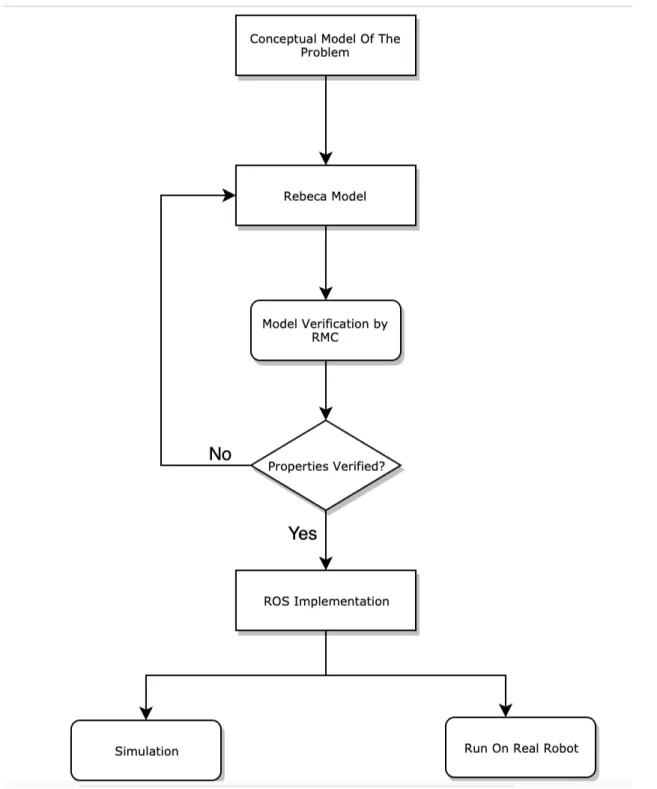
General approach of integrating the mentioned modules is to start modeling a robotic problem with a defined conceptual model for robotic programs. Then the conceptual model is modeled in Rebeca modeling language based on defined mapping rules which will be explained in the next chapters. Verification of the Rebeca model is carried by Rebeca Model Checker (RMC) and it may
need to edit the model several time before all the desirable properties are verified. Finally, the Rebeca model is mapped to the ROS implementation of the problem automatically and based on some mapping rules proposed in this thesis. This implemented version can either be run on the real robot or it can be run using a simulator for simulation purpose of the problem. A general view on the overall integration scenario can be seen in Fig 3.
1.2.
Research Questions
The research questions which are pointed to be answered in this thesis are defined in this section. During the thesis our goal is to answer these questions based on the research conducted on the previous work and experimenting different ideas on the problem. Three research questions defined at the start of this thesis can be can be defined as follows:
RQ: How can we model robotic problems in Rebeca?
the main focus of this question is on the first block of the integration process which is responsible to find a conceptual model for robotic problems. Answering this question gives a general mechanism to formally model each robotic problem in a level of abstraction which ignores implementation details of the problem.
RQ: How can we generate ROS code from Rebeca model automatically?
Modeling the conceptual model of the robotic programs by Rebeca that is done by the result of the first research question, it is required to find a meaningful and logical mapping between different entities in Rebeca and ROS. Then it would be possible to generate ROS-based robotic programs automatically.
RQ: What properties of robotic problems can be verified by the proposed integra-tion?
Although the modeled problem in Rebeca provides the possibility of checking desirable properties on the model by Rebeca Model Checker, the properties which can be verified on the model should be investigates since some properties may not be possible to verify on robotic models by Rebeca.
1.3.
Research Methodology
In this section we will explain the research methodology we have used for conducting research on the concerned problem. It is rather accepted among researchers that understanding the problem and defining some research goal or research questions is the first step to conducting any scientific research. However, defining research questions may be some how challenging if the problem is not understood clearly. In this conditions, applying feedback provided by the people involved in the research may help to improve the quality and clearness of the research questions. Finalizing the research questions gives researchers the opportunity to limit the scope of the problem. However, proceeding the research is not possible without acquiring proper background on different aspects of the problem. The next step is to find the related work to the concerned problem distinguish current problem from them based on some reasonable parameters. Investigating different mechanisms to find the proper solution for the problem is the next stage before conducting experiments to evaluate applicability of the conducted research. Finally, the report on the thesis is written and discuss different aspects of the problem that have been investigated and those which needs to be focused on in the future. An overview of the adopted research methodology in this thesis can be seen in Fig 4.
1.4.
Contributions
The major contributions in this thesis can be summarised as follows:
• Developing a mapping between a mobile robot programming model and a Timed Rebeca model for the model checking purposes.
• Developing a mapping between the Timed Rebeca model and ROS primitives for robot software implementation.
• Automatic generation of the ROS-based robotic program verified by (RMC).
1.5.
Report Overview
As an overview on the materials discussed in this thesis report we can structure the thesis by the following sections:
• Chapter 2 (Background and Related Work: Since, finding a mapping needs to have an understanding on the source and destination languages, a basic background on Rebeca modeling language and Robotic operating System concepts will be presented in this chapter. In addition, the related work to the context of this thesis including ROS programs verification and use of Rebeca in different purposes will be presented in the second section of this chapter. • Chapter 3 (Proposed Integration Mechanism): In this chapter the proposed mapping rules for modeling the general robotic problems in Rebeca will be explained in the first section. Then, the mapping mechanism between different entities in Rebeca and ROS entities will be discussed in the second section of the chapter.
• Chapter 4 (Experimental Results): In this Chapter, the applicability of the proposed framework in this thesis will be evaluated by doing experiment on some small scale robotic problems.
• Chapter 5 (Conclusion and Future Work): In the end, thesis outcomes will be concluded in this chapter and it will followed by the possible future work in the second section of the chapter.
2.
Background and Related Work
A basic knowledge on the Robotic Operating System (ROS) concepts will be convered in the first section of this chapter. This includes ROS infrastructure, topics, messages, publisher, subscriber and etc. Since, Rebeca modeling language and its model checking utilities is based on formal methods, a basic knowledge on formal methods and model checking methods will be discussed in the second section of the chapter. In the following, Rebeca modeling concepts including actors, message servers, reactive class and rebecs will be pointed out and some of Rebeca model checking tools such as Rebeca Model checker (RMC) and Afra [23] will be discussed in the same section. Finally in the last section of this chapter, the related work to the context of this thesis will be discussed which covers the work related to software verification of ROS-based robotic programs and the also the work related to integration of Rebeca modeling language with other frameworks on different purposes.
2.1.
Robotic Operating System (ROS)
Robotic Operating System(ROS) [11] is a robot middleware which has been widely used as an open source framework for the development of robotic applications and has become a standard in academic and industrial environments. ROS is not a real operating system, but a robotic soft-ware framework which its development started at Stanford University during the STAIR project, and later was founded in 2007 as an open source distributed software under the BSD license. At the moment the ROS infrastructure management has been deputed to OSRF. Currently, compa-nies like Yujin Roboticsin Korea, are using ROS for their research and academic activities in the development of robots.Similarly, new founded companies like Radney Brooks, Hartland Robotics, Yaskawa Motoman andTexte Technologies have accepted ROS as their software development frame-work. Since ROS introduces a software standard with specific interfaces in robotic development, it allows for the reuse of existing packages.
2.1..1 ROS Main Concepts
The main concepts in ROS can be seen in Fig 5 and in the following each concept will be discussed briefly.
Figure 5: ROS Main Concepts[24]
1. ROS Node: In the computation model of ROS, each ROS program consists of a number of nodes each of which is responsible to perform a specific task in the model and is able to
communicate with other node in the system through Topics and Services. In other words, ROS nodes are the main processing units in ROS and each specific tasks should be imple-mented as the functionality of a task. For example, one node could be responsible to control the robot’s wheel, one node to provide the graphical view of the robot, one node to manage the path planning task and the other one to perform the task of robot navigation.
Designing the system based on fine grained less coupled concept of nodes brings some positive points in terms of fault tolerance, code complexity, reusability and development cost. 2. ROS Topics: Topics originally designed to send data flow unilaterally and asynchronously.
They have provided the Publish / Subscribe communication mechanism at the top of ROS which will be presented in following of this section. Topics can be seen as the named chan-nels to send messages through. They conceptually provide anonymous message sending and eliminate the correlation between data generation and data usage. Generally, each node does not know the other nodes which it is communicating with, instead the nodes that need to receive certain data, register and subscribe to the topic which is assigned for that data. Sim-ilarly, the node that generates the data publishes these data on a related topic and multiple publishers or subscribers can send data on a specific topic. In other words, many to many communication is provided through this mechanism.
3. ROS Messages: Nodes communicate with each other by publishing messages on topics. A message is a simple data structure that consists of a number of field types. Basic standard types (integer, decimal, binary, and other common types) as well as arrays of these types are supported as data types in ROS. Defining a new message type in ROS is done by creating a msg file in the msg folder of the ROS package. Msg files are simple text files that define the data structure of the messages.
4. ROS Master Node: There is a special Master mode in the ROS system that provides naming and registration services for other nodes in the ROS system and allows publishers and subscribers to track topics and services. In other words, this node helps the nodes in the system to find each other and then communicate to each other directly. To run any ROS system, you must first run the roscore command. By executing this command, the Master node will be activated and runs other essential components.
5. Parameter Server: A parameter server is a shared and multivariable dictionary accessible through the network API. The nodes use this server to store system parameters at runtime. This means that the nodes can easily read and configure the configuration parameters and, if necessary, change them. Since this mechanism is not designed for high-performance ex-ecution, it’s best to use it only to store static data such as configuration parameters. The parameter server is designed based on XML / RPC and is run inside the Master node. 6. ROS Services: The Publish / Subscribe model is a highly flexible model for
communica-tion in a robotic system, but its many-to-many communicacommunica-tion and one-sided nature is not suited for synchronous interactions. Synchronous communication in ROS is provided through Services which includes a pair of messages: one for the request and one for the response. The node which provides the service (server node) establishes it under a string as the service name, and the client node sends the request and waits for an answer.
7. ROS Packages: Robotic software in ROS is created in a well organized way named pack-ages. A ROS package includes ROS nodes, ROS-independent libraries, datasets, configuration files and all the materials related to the current robotic software.
8. ROS Stacks: ROS Stacks can be considered as a higher layer over ROS packages such that Packages can be organized into ROS stacks. The promary goal of introducing stacks in ROS is to ease code sharing. while the main goal on packages is related to composable design. In addition, software distribution in ROS is provided by using ROS stacks.
2.1..2 ROS Communication:
The ROS framework at the lowest level provides an interface for sending messages by which al-lows inter-process communication. As stated above, in this context nodes are system processes that interact with each other using different ways. The ROS communication infrastructure is re-ferred to as the ROS middleware. In the following, we will briefly explain the different types of communications this middleware provides.
1. Asynchronous Message Communication: The Publish / Subscribe mechanism, which is the most used and most important method of communication in ROS, is an asynchronous queue-based and many-to-many messaging mechanism. In this mechanism, the sender node publishes its data on a named topic which is registered in Master node, and the receiver node subscribe to the topic which data is published on. Although sender and receiver do not know each other directly, they should be registered by the Master node and then the direct communication will be provided between them by the Master node. As an illustrative example of communication through Publish/Subscribe mechanism we can refer to Fig 6.
Figure 6: Publish/Subscribe Communication Method.
2. Save and Post Mechanism: Since the Publish / Subscribe system is anonymous and asynchronous, the data can be easily saved and resent without requiring a change to the code. For example, assume that Task A reads the data from the sensor and Task B is responsible to process data generated by Task A. ROS allows the data published by the fist task to be stored in a file, and then these data are subsequently released from the file to be received and processed by the second task. This design pattern can help increase the flexibility and modularity of the system. An example of message transmission through Topic can be seen in Fig 6.
3. Service Call: Asynchronous nature of the Publish / Subscribe communication mechanism is applicable to most robotic communication needs, but sometimes there is a need for syn-chronization request / response between processes in a robotic programs. Asking the current state of a node can be considered as an example of this type of communication between the nodes in a robotic system. The ROS middleware provides this feature through Services by which the server node provides a specific service which can be called by the client nodes in a synchronous way. Similar to the ROS topics, each ROS service should be assigned by a specific data type which is defined by srv file in the ROS package.
Figure 8: ROS communication through services
2.1..3 ROS Syntax:
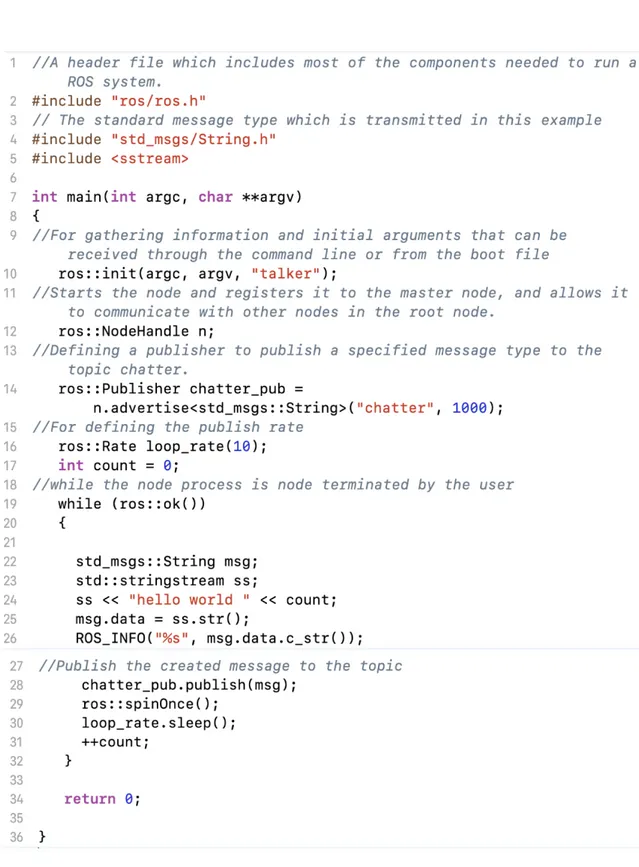
In this section of the thesis, we will explain the ROS syntax since it is required to have a ba-sic knowledge on how to define different entities when we are going to find a mapping between two different syntax. ROS programming is provided by different programming languages such as C++ and Python by introducing ROS client libraries. In this thesis, we have focused on ROS programming by C++ as it is more desirable to the system developers and designers. Explanation of the ROS syntax in this section will be based on a simple example containing a publisher and subscriber. The general overview of this example can be seen in Fig 9. In this example, there is
Figure 9: Simple Example of ROS Programming
as the communication channel between publishers and subscribers in this example. In addition, there is another node Subscriber which subscribe to the mentioned topic to perform a function on receiving any message published by the publisher. The ROS code and its explanation written in C++ language for the publisher ROS node can be seen in Fig 10.
The ROS code and its explanation written in C++ language for the publisher ROS node can be seen in Fig 11.
2.2.
Formal Methods
Formal methods can be considered as mechanisms which are used to model complex systems as mathematical entities [25]. The superiority of formal methods to the rest of the system design methods is to proof the correctness of the design through mathematical models. The formal meth-ods are known as a basic and expected component of system design, which can be categorized into two types of formal description or specification and formal verification [26]. Formal specification is used to make a formal representation of a system and its expected features, while the main purpose of formal verification is to analyze the system based on the desirable properties. The field formal verification is mostly applicable in the analysis and verification of the complex and critical systems; examples of these systems are the air traffic control system and defense systems. Generally, during the development of such systems, a high percentage of cost and energy in the development process is spent on test and debugging of the system.
As the complexity of the system increases, the cost of the debugging or test will be increased and it will be necessary to complete these steps more efficient. Although Simulation and Emulation can be considered as two basic and easy to understand techniques for debugging and testing the system, they are not efficient in terms of cost, resource consumption and accuracy. An efficient and accurate technique to test and verify a system based on some desirable properties is Model Checking which will be described briefly in the following sub section.
2.2..1 Model Checking:
In a general view, in model checking, the main goal is to check whether the system fulfills the requirements or desired properties that this is done by exploring all the states which a model can have in its state space [27]. This process proceeds step-by-step and if the model satisfies the desired properties, then at the end the model state space is created, which includes all the states that can be reached for the system. On the other hand, if one of the properties is violated, the process of model checking stops and a Counter Example is generated that indicates the path from the initial state to the state in which the property is violated. By analyzing this counter example, we can determine which transition leads the system to an unwanted state has violated the expected property. Model checking systematically performs a comprehensive search on all states of the system, therefore the error that is recognized during the model checking process is always considered as a real error.
Despite all the positive points on Model Checking methods, for complex systems, the state space for the system can be very large. This is due to the fact that the states associated with different components of the system are combined, and the number of states increases exponen-tially. Therefore, state space explosion may occur which is the biggest objection to model checking methods. A general view on the system design based on model checking methods can be viewed as Fig 12.
2.3.
Rebeca
2.3..1 Rebeca Modeling Language
Rebeca is an actor-based modeling language developed to facilitate formal verification of concur-rent applications. Form the modeling view, each model in Rebeca is composed of a number of instantiated actors which are called reactive objects or rebec. The communication between rebecs are done through message passing which is provided by introducing Message Servers in Rebeca. In other words, ”Computation takes place by asynchronous message passing between rebecs and execution of the corresponding message servers of messages. Each message is put in the queue of the receiver rebec and specifies a unique method to be invoked when the message is serviced”
Figure 11: Subscriber Node Code For The ROS Simple Example
[23]. The Rebeca syntax can be seen in Fig 13. Each Rebeca model includes a set of reactive class declarations and a main function. The main function defines instances of reactive classes, called rebecs. Each reactive class comprises the following five parts:
1. Knownrebecs: The rebecs to which the rebecs of this class may send/receive message to/from.
2. State variables: Local variables that in combination with the queue content, indicate the state of a rebec of this class. From the verification view, the state of a rebec is determined based on the current state of the rebec’s queue as well as the value of the state variables of the rebec. Similar to Java, the data type assigned to a state variable can be int, byte, short , boolean or it can be a reactive class name which is used to refer to other actors.
3. Constructor: Similar to object oriented programming languages, the constructor in Rebeca is called when the rebec is instantiated and it can be used to initialize the value of the state variables.
4. Message Servers: Specify how a rebec of this class processes incoming messages. Each rebec takes a message from its message queue and executes the corresponding message server. Execution of a message server body takes place atomically (non-preemptively). The behavior of a Rebeca model is defined as the parallel execution of the released messages of the rebecs. 5. Usual Methods: In addition to the message servers in Rebeca, another kind of methods can be defined in a model that is only accessible by the current rebec. Another point to mention is that usual methods can only call the message servers of the current rebec and they can also return a value as the returning value while Rebeca message servers have no returning value.
Figure 12: System Design Based On Model Checking
Although in the primitive versions of Rebeca, modeling timing aspects of the problem was not provided, this was facilitated in Timed Rebeca which was design to focus on the real-time problems. In TRebeca, each rebec has its own local clock, but there is also a notion of global time based on synchronized distributed clocks of all the rebecs. Timing primitives are added to the Rebeca syntax to cover timing features that a modeler might need to address in a message-based, asynchronous and distributed setting. These primitives include the following:
1. Delay: delay(t), increases the value of the local clock of the respective rebec by the amount t.
2. Delay: r.m() deadline(t), after t units of time the message is not valid any more and is purged from the queue (timeout).
3. After: r.m() after(t), the message cannot be taken from the queue before t time units have passed.
A sample Timed Rebeca reactive class is depicted in Fig 14.
2.3..2 Rebeca Model Checker Tools
Although the semantics introduced by Rebeca was easy and understandable for the system de-signers, it was required to have a powerful model checker to verify the desirable properties of the designers. Before designing a direct model checker which can directly verify a modeled problem in Rebeca, designers had to convert Rebeca models to a middle language which had a direct model checker. The first direct model checker for Rebeca was Modere which was introduced in 2005. In Modere, model checking was performed by LTL methods.
RMC: Rebeca Model Checker (RMC) was the redesigned and re-engineered version of Modere. Simiar to Modere, RMC is also a direct model checker which is able to perform model checking
Figure 13: Rebeca Modeling Syntax [23]
process without need to any middle conversion or third part tool. So far, different versions for Rebeca have been released and the last version which is published on Rebeca official website is RMC 2.6 that is available for different platforms. In this version, there is improvement in terms of efficiency, flexibility and scaleability by the changes applied on model checking algorithm, state space management policy and model translation strategy.
Afra: As a mature modeling language, having an Integrated Development Environment (IDE) was needed in among the people in the designers community to have more control over the modeling aspects of the problem. Afra is the first IDE designed specifically for Rebeca that integrates Rebeca modeling aspects, Rebeca Model Checker (RMC), counter example visualization and all the tools required for modeling a problem. Afra is a Eclipse based IDE which has three different parts project browser, model and property editor, and model-checking result view. Afra 3 is the last version released as a free product by the Rebeca development team.
Figure 14: Sample Reactive Class [23]
2.4.
Related Work
In this section, a brief explanation of the studies carried out on the scope of the problem will be presented. Generally, the work related to the scope of this thesis can be grouped into three categories: 1) formal verification of robotic programs, 2) code synthesis from formal models and 3) Rebeca integration with other frameworks. In the following, we will elaborate some outstanding contributions belonging to each category.
2.4..1 Formal Verification of the robotic programs:
A formal verification approach for industrial robot software is proposed by Webster et al. in [28]. They use SPIN model checker as the verification component in their proposed method. Although the result achieved by their method is considerable, it is limited to a specific robot type ( ”Care-o-Bot” robot [29]) and is not also generalized to the domain of all ROS programs. Huang et al. [30] propose ROSRV as a runtime verification framework for ROS programs. ROSRV verifies the security and safety of robotic applications by adding a separate ROS node monitoring the behaviour of the other ROS nodes in the application. In this proposed method, a new master node is created which acts a the system monitor, and security policies are defined as user input configuration. For each message that is exchanged in the system, the monitor node decides whether the sent message is allowed to reach the receiver node based on these security policies or not. Therefore, you can prevent unsafe requests such as sending a shut down message to the master node. In other words, unacceptable states which lead the robot’s behaviour to violate the desired properties are predicted and prevented by the monitor node added to the system. One of the defects of the method presented in this article is that it relies entirely on network routing, and in particular on IP addresses to ensure security. Another defects of this method is the scalability, since a centralized solution is provided and all communication messages are monitored centrally which imposes an overhead on the inter-robot communications. Therefore, this method is not scalable for systems with a high number of nodes. The final problem is the lack of formal verification in this method such that it is still necessary to create a formal model from the ROS program and prove that the generated monitors guarantee the desirable properties in the system.
They have introduced a domain-specific language named DeRoS, to define the desired safety prop-erties. Similar to ROSRV, a monitor node is automatically added to the application to monitor the behaviour of the other nodes. However, due to the reliance on only a single monitor for the whole application, scalability is the common limitation for both of these methods.
2.4..2 Code Synthesis:
There are some research conducted on robot code synthesis from a model verified by formal meth-ods. Li et al. in [32] design a code synthesis method to generate the executable C++ code from the timed automata verified model. In their method, the ROS code is generated from a Timed Au-tomata [33] model verified on some desirable properties such as deadlock and safety by Uppall [21]. However, multi agent robotic problems are not concerned by their methods. Mobility of the robots is also ignored in the proposed mechanism. SCADE [34] is another tool which has formal basis, and has been successfully applied in a variety of applications not only robotic problems. Times tool [35] is a prototype C-code generator which automatically synthesizes the C code from Timed Automata extended with tasks. However, SCADE and Times have no support for ROS-based systems as the most popular robotic framework in the industry and academia. On the other hand, the advantage of Timed Rebeca other timed modeling languages like TCCS [36], Real-Time Maude [37], and Timed Automata is its intuitive and easy-to-use syntax and the actor-based paradigm of modeling in which there is no need for any knowledge of formal methods [38].
2.4..3 Rebeca Integration With Other Frameworks
In [39] a simple algorithm for converting UML models into Rebeca models is presented. The purpose of this work was to provide a way to have accurate SoC chip design in transaction-level. In this regard, a design methodology is presented in which first the design must be done in the form of usecase diagrams, class diagrams, sequence diagrams, and activity diagrams. Then the diagrams are converted to Rebeca model according to the proposed mapping algorithm. Finally, the Rebeca model is verified using Rebeca verification tools. This algorithm assigns each of the UML diagrams a reaction class in Rebeca. The variables in this diagram will be reactive class state variables, and each of the methods will be mapped to a message server.
Behjati et al. propose a mapping from SystemC designs to Rebeca language named RebecaSys in [40]. This has been done to verify the correctness of SystemC designs. The performance of the implemented tool (Sytra) has been examined on some use cases ranging from small scale to medium scale and the most important use case which resulted in a good performance is related to a MIPS process named mmMIPS. Aceto et al. in [41] have proposed a mapping strategy between Timed Rebeca [22] and Erlang programming language. This research has primarily done to be able to set Rebecas timed variable by different values. Then check the appropriateness of the values set to each variable by McErlang tool to find the most appropriate value for each variable.
3.
Proposed Method
In this chapter we will present the proposed method on integrating Robotic operating System (ROS) and Rebeca modeling language. As it was mentioned in the first chapter, the general integration approach taken by this thesis is to start modeling a robotic problem with a defined conceptual model for robotic programs. Then the conceptual model is modeled in Rebeca modeling language based on defined mapping rules which will be explained in the following. Verification of the Rebeca model is carried by Rebeca Model Checker (RMC) and it may need to edit the model several time before all the desirable properties are verified. Finally, the Rebeca model is mapped to the ROS implementation of the problem automatically and based on some mapping rules proposed in this thesis. This implemented version can either be run on the real robot or it can be run using a simulator for simulation purpose of the problem.
3.1.
Problem Formulation
3.1..1 Conceptual Model
Since Rebeca is a general modeling language that can be used to model different distributed systems, it is necessary to define a conceptual model of robotic problems in order to limit the scope of the problem. In this sectino we define conceptual model for mobile robotic problems which are concerned in this thesis.
Generally, in a mobile robotic program, there are a number of robots capable of moving in the environment and communicating with each other. Therefore, we assume that the system is composed of M robots R = {Ri : i = 1, 2, ..., M } such that:
Ri= {pi, Vi, Ai, Si}
Each robot Ri has a command port pi which is used as the communication bridge between the
central controller and robot Ri. Additionally, each robot has N properties which are defined by
set Vi = {vij : j = 1, 2, ..., N }. Since robots are responsible to do some activities, K activities
are assigned to each robot Ri that are defined by Ai = {(aij, eij) : j = 1, 2, ..., K} in which each
activity aij has an estimated execution time indicated by eij. Finally, for sensing the environment
and providing the required data, each robot Ri is accompanied with U sensors Si= {(sij, srij) :
j = 1, 2, ..., U }. Each sensor sij has a specific function which is run when each unit of data is
sensed by the sensor. The time between sensing two units of data is specified by the sensing rate of the sensor which is indicated by srij.
It is worth mentioning that in some robotic systems there is a central controller which monitors the behaviour of robots and sends them some commands. This central node has some tasks to do which are modeled by CT = {ctj : j = 1, 2, ..., T }. It also may have some variables to store the
state of the system that can be modeled by CV = {cvj : j = 1, 2, ..., W }. Therefore, the central
controller can be defined as follows:
CN ode = {CT, CV }
An example of a general robot programming model can be seen in Fig 16. In this example, there are two different types of mobile robots and a central controller. Each robot has a single activity with a specified execution time. The central controller is the node that decides which robot should run its activity. Each robot reports its current state to the controller after executing its activity. Sending commands from central controller to a robot is done through that robot’s port. In this example, we assume that each robot has only one sensor which provides data to the robot in a specified sensing rate. Notice that each robot has a single activity, which is movement in a specif direction (R1 in direction X and R2 in direction Y). Each robot should update its new position and let the controller know about its current position. The controller decides which node should move at each time and the movement should be done in such a way that no collision happens between the robots. This process is repeated until each robot reaches its goal which is de-cided by the controller. The formulated version of the provided example can be specified as follows:
Figure 15: A simple example of a general robotic problem model R = {R1, R2} R1= (p1, V1, A1, S1), V1= {v11}, A1= {(a11, e11)}, S1= {(s11, sr11)} R2= (p2, V2, A2, S2), V2= {v21}, A2= {(a21, e21)}, S2= (s21, sr21) CN ode = {CT, CV } CT={(ct1, ec1), (ct2, ec2), (ct3, ec3)}, CV = {cv1, cv2, cv3} 3.1..2 Rebeca Model
As it was mentioned in the previous chapter, each Rebeca model RM is composed of M reactive classes such that RM = {RCi : i = 1, 2, ..., M }. Each reactive class RCi has N message servers
specified by Mi = {mj : j = 1, 2, ..., N }. In addition to message servers, there might be M local
methods defined for each reactive class, which are defined as Li = {lj : j = 1, 2, ..., M }. The
knownrebec set of a rebec is specified by Ki = {kj: j = 1, 2, ..., K}. Finally, each rebec has a set of
S state variables which are defined by Ci = {cj : j = 1, 2, ..., S}. Accordingly, each reactive class
in the Rebeca model can be defined as follows:
RCi= {Mi, Li, Ki, Ci}
3.1..3 ROS Model
There are different styles of programming developers may use to program in ROS. One common and accepted method of programming in ROS, is object-oriented, in which developer defines a class per each active node. Then include all the methods and variables related to the node in that class. We assume that a ROS package for a robotic program is composed of M different class definition such that ROSM odel = {ROSClassi : i = 1, 2, ..., M }. After defining the overall structure of
the ROS nodes by defined classes, each active ROS node is an instantiated object of a specific class. Since we may have more than one created object of the same class, the set of active nodes in ROS can be defined as ROSN ode = {rosnodei : i = 1, 2, ..., B}. As it was mentioned in the
previous section, there are a number of defined and predefined topics in each ROS program that can be showed as T = {ti: i = 1, 2, ..., N }. It should be mentioned that communication protocol in
ROS is designed based on publish-subscribe protocol in which each node can publish on a specific topic or subscribe to the topic to receive the data published on the topic. Publish state of the node rosnodei on the topic tj is indicated by publishij. Therefore, the list of the topics which
the node rosnodei published on them can be showed by P ublishi = {publishij : j = 1, 2, ..., N }.
In the same way, the list of topics which the node rosnodei subscribes on them is defined by
Subscribei = {subscribeij : j = 1, 2, ..., N }. Finally, as it was mentioned in the previous section,
each topic has a specific message type to be published on the topic. Therefore, the list of message types in the ROS package is defined by M T = {mti : i = 1, 2, ..., N }. In ROS, the data sensed
by sensors are published on some specific topics per each sensor. Therefore, if a node wants to perform on the sensed data, it should subscribe on the related topic to the sensor and consider a method in the defined class for the node.
3.2.
Modeling Robotic Problems In Rebeca
Since Rebeca is general purpose, we need to find a mechanism to model robotic programs in Rebeca. In this section, we present a mapping between general robotic model elaborated in the previous section and Rebeca modeling language.
Individual robots to reactive classes: It was mentioned in section 3.1..1 that we have a number of independent robots in the general model in which, each robot has its own properties and behaviour. On the other hand, each independent actor is modeled by a reactive class in Rebeca, and each reactive class can have its state variables, methods and message servers which represent the actor behaviour. We map each robot in the general model to a reactive class in Rebeca. Since we may map other objects in the general model to reactive classes in Rebeca, we annotate the reactive classes mapped from robots by @Robot. Therefore, each Ri in robot set R of the defined
conceptual model for a specific robotic problem is mapped to RCi in the Rebeca model of the
problem and this reactive class is annotated by @Robot to be distinguished from other types of reactive classes which will be explained in the following.
Figure 16: Individual robots to reactive classes
Sensors to recursive message servers: As it was mentioned, each robot consists of a number of sensors each of which has a specific function which is run when a unit of data is sensed by the sensor. On the other hand, it is obvious that each sensor has a specific sensing rate which indicates the time interval between sensing two units of data. Therefore, we consider a message server annotated with @Sensor per each sensor of the robot in its corresponding reactive class. Since reading sensor data is a repetitive task, the message server assigned to the sensor should call itself after t units of time that t is the sensing rate of the sensor. This can be done by using keyword after(t) in Timed Rebeca. An example is depicted in Fig 17.
Activity to message server: Modeling the activities of a robot in Timed Rebeca is done by defining a normal message server (without annotation) in Timed Rebeca. In other words, for
Figure 17: Sensors to recursive message servers
each activity aia message server is considered in the robot’s reactive class. It is worth mentioning
that each activity has an estimated execution time ei which can be modeled by delay(ei) in Timed
Rebeca. This type of message servers are not annotated as they are usual message servers. A simple example can be viewed in Fig 18.
Figure 18: Activity to message server
Property to state variable: In the general model, each robot may have some properties. On the other hand, there is a special section named statevars in Rebeca which includes a set of variables to hold the current state of a rebec. We map each robot property to a state variable in the section statevars of the corresponding reactive class.
Controller to reactive class: The point which makes the central controller node different from robots in a robotic program, is its ability to directly communicate with all the robots in the system. Therefore, we consider a special reactive class annotated with @Controller for the central node which has all the rebecs annotated with @Robot in its Knownrebecs section and vice versa. It should be mentioned that we map controller’s tasks and variables to message servers and state variables, respectively. An illustrative example can be seen in Fig 20.
Command port to @Port message server: The command port introduced in the previous section, is mapped to a message server annotated by @Port in the reactive class corresponding to the robot. All the commands and messages should be sent to the robot from the controller node through this @Port message server.
Figure 19: Property to state variable
Figure 20: Controller to reactive class
3.3.
ROS Code Generation From Rebeca Model
Modeling a robotic program in Rebeca gives the opportunity to check desired properties such as safety and timeliness. However, the Timed Rebeca model is not executable and cannot be run on real robots. Therefore, after verifying the desired properties on the Timed Rebeca model using Rebeca Model Checker (RMC), the Rebeca model is translated to a ROS program.
@Robot reactive class to C++ class: In an object-oriented programming language like C++, class is a structure which defines the state and behaviour of the objects in the program. Similarly, reactive classes in Rebeca have the responsibility to define the overall state and behaviour of the rebecs. ROS provides client libraries in several programming languages such as C++ and Python. In this paper, we use C++ considering its popularity among robotic programmers. In ROS programming, there should be a C++ class per each robot to include all the behaviour and states related to the robots. Then, each object of the defined class should be mapped to a ROS node. Therefore, we consider a one to one mapping between Rebeca reactive classes which are annotated by @Robot and C++ classes in ROS programs. A simple example is depicted in Fig 21. Global variables to parameter server entries: In a Rebeca model, there might be some global variables which are accessible to all the active rebecs in the model. Since all the entries in the ROS parameter server are valid and accessible for all the active nodes in a ROS program, we can map global variables in Rebeca model to entries in ROS parameter server.
State variables to private variables: All the state variables of a reactive class are only valid in that class. On the other hand, all the private variables defined in a C++ class can only be accessed through the methods defined in that C++ class. Therefore, we map state variables in the Rebeca model to private variables in the ROS program.
Figure 21: @Robot reactive class to C++ class
Unannotated message servers to methods, subscribers and publishers: Each message server in Rebeca is composed of different parts. Here we find a mapping for each part:
1. Message server name: Since rebecs in Rebeca communicate in an asynchronous way, it is easy to map rebec communications to the publish-subscribe model in ROS. Therefore, the name of each normal message server in Rebeca is mapped to a topic name in ROS.
2. Message server parameter: Since each topic in ROS should be limited to a specific message type, we map the list of parameters of a message server to a message type in ROS and then assign that message type to the topic corresponding to the message server. 3. Message server caller: In the Rebeca model, there might be a number of reactive classes
in which a message server is called. If we assume the caller reactive class is class A, then there should be a publisher in the C++ class mapped from reactive class A to publish on the corresponding topic.
4. Message server holder: Since the message server caller has a publisher to publish on the topic associated with the message server, there should be a subscriber in the C++ class related to the message server holder to act as soon as the message server is called.
5. Message server body: Since the message server body should be run when the message server is called, it will be mapped to the call function of the subscriber defined in the C++ class mapped from the holder reactive class.
@Sensor message servers to subscribers: The difference between normal message servers and the message servers annotated by @Sensor is related to their publisher. In fact, in a sensor message server, there is no publisher defined by the developer as the physical sensor publishes the data. Therefore, this type of message server is mapped to a subscriber in the C++ class. Similar to normal message servers, the body of this message server is mapped to the call function of the subscriber. It is worth mentioning that, since there is no physical sensor in the Rebeca model to generate the modeled data, model designer can use either deterministic or random values in the message server body to model the sensed data.
@Controller reactive class to controller C++ class: In the Rebeca model, the reactive class annotated by @Controller is considered as the central controller which has all the system’s rebecs in its knownrebecs section. Similar to @Robot reactive classes, the @Controller reactive class is mapped to a C++ class in the ROS model. However, there is a difference between previous C++
class and the controller C++ class; There should be a special topic named control bridge which is used for communication between the central controller and all the nodes in the ROS program.
@Port message server to Port topic: Each robot has a @Port message server which is used for communication between the central controller and the robot. This message server is mapped to a special topic named Port for each robot. Then the C++ class mapped from the @Robot reactive class should subscribe on the specified topic, since the central controller should have a publisher per each robot’s port topic. The body of the message servers is mapped in the same way as the typical message servers.
Sender Keyword: In Rebeca modeling language, Sender keyword is intended to refer to the rebec which has called the current message server of the current rebec. To implement the same functionality in the ROS code, we can add a field of the string type to the message type we create and send the name of the sender using this way. However, in the latest version of ROS, developer can access the publisher’s name by subscribing to a Message Event object for the concerned message type. In addition to the name of the publisher, additional metadata for the message is also available. Therefore, it can be said that it is syntactically possible for the receiver node to recognize the message publisher. However, the creation of an application whose functional logic needs to know the publisher’s name is not recommended among ROS developers community. Self Keyword: The keyword Self in Rebeca modeling language is used to refer to the current rebec and call its messenger servers. Since the methods of a Cpp class can be called directly by instances of that class, we do not need to map the keyword ”self”.
Delay function: Delay is an expression in Rebeca that is used to model the running time of the functionalities. The runtime of each Rebeca expression is assumed to be zero, except for the expression that Rebeca modeler has defined delay on them. In ROS, the execution time of the regular expressions is very low, but when it is necessary to act and move in some conditions there is a significant delay. Therefore, Rebeca modeler should use Delay function in such cases. This can be semantically related to the execution time of the robot behaviours.
Non Deterministic Expressions: Non deterministic expressions are used to model uncer-tain behaviors of a system. The expression X =?(e1, e2, ..., en) assigns randomly one of the values in the parenthesize to variable X. implementing the same functionality in ROS is done through Rand() function.
An explanatory example on the defined mapping rules can be seen in Fig 22s.
Rebeca Entity ROS Entity
@Robot reactive class Independent C++ class Global variables Parameter server entries State variables Private variables in C++ class Message server name Topic name
Message server parameters Message type Message server holder Subscriber
Message server body Subscriber callback function @Sensor message server Subscriber on real sensor topic
@Contoller reactive class controller C++ class with publisher on all command topics @Port message server Publisher-Subscriber on Command topic
Reactive class Constructor Method C++ class Constructor Method Local variables in reactive class Local variables In C++ class
Rebec creation in models main function Object creation in main function of the model Sender reference Sender parameter in the created message type Delay() function Sleep() function in ROS
Non-deterministic Values Rand() function
typical logical and mathematical statements their equivalents in C++
Table 1: Overview of mapping between different parts Of Rebeca models and ROS programs Basic Robot Actions: We have modeled the general robotic model so far. But as we are thinking about implementing the ROS version of the model, some basic decisions such as the movement of the robot should be taken into account. In this paper we only consider robot’s movement as the basic action although some other action could be considered. For each movement, the source and destination positions should be specified in the Rebeca model so that we can generate
the required codes in the ROS program. Imagine the current position of the robot is (x,y). Then, it can move to any of the eight locations around it. We can model these movements using simple annotations like @Move(X-1,Y-1). It is worth mentioning that this annotation is ignored by RMC during verification of the Rebeca model. In the mapping process, we generate a special topic per each robot which is used by ROS to decide about the robot’s movement. In ROS, this topic is known as CMD topic.
4.
Validity Experiments
In this section we will present the experiments which have been done to evaluate the validity of the proposed integration mechanism.
4.1.
Tool Implementation:
After finalizing the integration mechanism, a Java program was implemented to automate the mapping process of the Rebeca models to ROS code.
The Rebeca To ROS convertor program consists of reactive class converter, message server converter, main function converter, kernel expression converter, TRepeca expressions converter, a class for data type conversion, and a class for generating ROS package and its files. The output of each run of this program consists of the ROS package corresponding to the input Rebeca model. The generated package is in accordance with the general structure of the ROS packages, including launch, src, msg and include folders. The generated msg files, which are related to the definition of the custom message types, will be placed in the msg folder. As it was mentioned in the previous chapter, each reactive class will be mapped to a ROS node that is defined in a cpp class. The header file associated with the generated node class definition is created in in Include folder and its cpp file will be generated in the src folder. The launch folder includes a node setup file in which the nodes configuration and parameters as well as general parameters are defined. Generating different entities in ROS are done in each node’s cpp class based on the mapping rules defined in the previous chapter.
For illustrative purposes, we used the Stage simulator to execute the ROS program generated from the Timed Rebeca model. Two different versions of Kabuki and Turtlebot robots were used in this simulation. Moreover, for model checking the Rebeca model, we used Afra which is a tool provided by Rebeca development team. Afra uses RMC in the background.
4.2.
Validity Experiment 1 (Single Robot, Recursive Task):
4.2..1 Experiment Description:
In this experiment, we consider a single mobile robot which is responsible to perform a repetitive task of moving in a single direction for a specific number of steps and then return back to the start point. However, we consider a specific property fuel capacity for the robot and a defined value of fuel is consumed per each moving step. When the robot’s fuel level is lower than a specific threshold, the robot has to stop for a couple of time to be recharged by the operator and then it can continue its task. The general moving scenario of this experiment can be seen in Fig 23. The conceptual model of this experiment, based on the defined conceptual model in this thesis, can be seen as follows:
R = {R1}
R1= (p1, V1, A1), V1= {f uelCapacity, f uelP erStep, f uelLevel, moving},
A1= {moveF orward(a11, e11), moveBackward(a12, e12)}}
As it can be concluded from the conceptual model, in this experiment we have only one robot R1
which has two different tasks moveForward and moveBackward that are used to move to the next and the previous segment respectively. The estimated execution time of activities are modeled by e11anda12respectively. As it was mentioned in the experiment description, the robot has four
properties Fuel Capacity, Fuel Consumption Per Each Moving Step, Fuel Level and Moving (to show if the robot is moving or not) and the robot should stop for a specific time whenever the robot’s Fuel Level is lower than a specific threshold defined by the system designer. For more clarification, the sequence diagram of this experiment is depected in Fig 30.
4.2..2 Rebeca Model:
After defining the conceptual model of the problem, the Rebeca model of the experiment should be generated based on the mapping rules defined in the previous section on modeling robotic problems in Rebeca. The Rebeca model of Experiment 1 that is implemented in Afra can be seen in Fig 25.
Figure 23: Genral Moving Scenario Of Experiment 1
4.2..3 Property Verification and Method Applicability Check:
In this case study, we have a single robot moving in the environment. We were interested to ensure that the robots stops moving when the remaining fuel is lower than threshold. Fuel Guranteed can be considered as a desirable property which should be checked to ensure that the remaining fuel of the rebot is always higher than the specified threshold.. The Fuel Guranteed property to be checked by Afra can be defined as follows:
P roperty {
Def ine{
fuelThreshold = 15;
f uelCheck = (robot1.remainingfuel < f uelT hreshold);
} Assettion{
F uel Guranteed :!(f uelCheck); }
}
Checking the property by Rebeca Model Checker (RMC) shows that the property is satisfied which means in all the states of the model, the remaining fuel of the robot never goes lower than the specified threshold. Then we changed the Rebeca model in a way that the condition statement for checking remining fuel was changed. Then the property was checked again and in this time the property was not satisfied and a counter example was generated which means that theres is at least one state that leads to the situation in which the remaining fuel of the robot is lower than the specified fuel threshold.
To check the applicability of the proposed method, we generated the ROS code related to this case study. Checking the variable related to the remaining fuel of the robot in the runtime showed that it never goes lower than the specified threshold. It was also visited that in the fuel requiring conditions, robot stops for a coupe of times and then continue its way to the destination.
4.3.
Validity Experiment 2 (Two Robots, Central Controller):
In this experiment, we were interested to evaluate the applicability of the proposed framework in the area of multi robot systems.
4.3..1 Experiment Description:
The main focus of this experiment is on multi robot environments in which there is a central node to control the behaviour of the nodes in the environment. In this experiment, there are two different types of mobile robots and a central controller. Each robot has a single activity with a specified execution time. The central controller is the node that decides which robot should run its activity. Each robot reports its current state to the controller after executing its activity. Sending commands from central controller to a robot is done through that robot’s port. Notice that each robot has a single activity, which is movement in a specif direction (R1 in direction X and R2 in direction Y). Each robot should update its new position and let the controller know about its current position. The controller decides which node should move at each time and the movement should be done in such a way that no collision happens between the robots. This process is repeated until each robot reaches its goal which is decided by the controller. The overall view of the system can be seen in Fig 26.
The conceptual model of this experiment, based on the defined conceptual model in this thesis, can be seen as follows:
R = {R1, R2}
R1= (p1, V1, A1), V1= {id, stopped, position},
A1= {(M oveInY, e11)},
R2= (p2, V2, A2, S2), V2= {id, stopped, position},
A2= {(M oveInY, e21)}
![Figure 1: Robot Middleware In The System Architecture [8].](https://thumb-eu.123doks.com/thumbv2/5dokorg/4694148.123218/7.892.317.570.140.681/figure-robot-middleware-architecture.webp)
![Figure 2: Comparison Robot Programming Frameworks Based on Some Factors [16].](https://thumb-eu.123doks.com/thumbv2/5dokorg/4694148.123218/8.892.131.765.562.844/figure-comparison-robot-programming-frameworks-based-factors.webp)

![Figure 5: ROS Main Concepts[24]](https://thumb-eu.123doks.com/thumbv2/5dokorg/4694148.123218/13.892.129.751.709.1063/figure-ros-main-concepts.webp)


![Figure 13: Rebeca Modeling Syntax [23]](https://thumb-eu.123doks.com/thumbv2/5dokorg/4694148.123218/21.892.136.763.133.797/figure-rebeca-modeling-syntax.webp)
