VTlnotat
No: TF 52-03 Date: 1986-12-19
The Feasibility of Measuring
Road Surface Microtexture
by Means of Laser Techniques
Author: Stephen E. Samuels
Title:
Division: Road User and Vehicle Division Project no: 52014-8
Project title: Mätning av mikrotextur med hjälp av elektrooptiska givare
Sponsor: VTI
Distribution: free
' . Pa: 5__81 01 Linköping. Tel:_013-2Q 40_ Telex 50125 VTISGIS. Telefax 013- 14 14 36
Instltutgt Besok. Olaus Magnus vag 3Z Lmkopmg
ACKNOWLEDGEMENTS
The work reported herein was conducted in the Acoustics Laboratory of the Swedish Road and Traffic Research Institute during the author's period as a Visiting Research Fellow at the Institute. This opportunity to work at the Institute is gratefully acknowledged. The assistance of the Institute staff in conducting the work was much appreciated.
Remplir AB, Stenkullen, Sweden, provided the laser system used for the study on a free of charge loan. The generous cooperation and assistance from Remplir AB is also gratefully acknowledged.
The author
The participation of Mr. Samuels was made possible by the courtesy of the ARRB, particularly the Executive Director, Dr. M. Lay and the Deputy Director, Dr. J. Metcalf. Their kind and cooperative attitude is gratefully acknowledged.
CONTENTS ACKNOWLEDGEMENTS ABSTRACT BACKGROUND Macrotexture measurements Microtexture measurements Quantifying microtexture '. "l '" 't "" "" U N F -4 EXPERIMENTAL TRIALS Laser equipment Instrumentation system Trials
Amplitude profile data Frequency spectral data
N
P
P
N
N
N
W D W N HANALYSES AND INTERPRETATIONS l Known surfaces
1.1 Amplitude profiles .1.2 Frequency spectra
2 Sample surfaces
4 CONCLUSIONS AND RECOMMENDATIONS REFERENCES Page m m b www N i -' l -d l -J b -IC D \ I \ I \ I F. : 13
ABSTRACT
Laser systems have hitherto been applied to the measurement of road surface profile and macrotexture. This report outlines a brief study of the feasibility of applying laser techniques to the measurement of road surface microtexture. Measurements were conducted on both known square wave and sawtooth wave surfaces and on a range of typical Swedish road surfaces. Both amplitude profiles and frequency spectra of the surfaces were obtained. It was concluded, particularly on the basis of an analysis of the frequency spectral data, that the feasibility of the technique had been demonstrated. It was recommended that a system be developed fully and evaluated. Further, an improved means of indepen-dently measuring microtexture in the laboratory is required to facilitate
system calibration and correlation of system outputs with known
l BACKGROUND
1.1 Macrotexture Measurements
Laser transducers have been successfully applied to the measurement of
road macrotexture for several years (Sandberg 1984 and 1986). Initially
the technique has involved the constant speed traverse of a transducer
over a l m section of road surface. To do this, the laser transducer is
incorporated in a rig which merely sits on the road surface. Data, recorded on tape during each traverse, are subsequently analysed in the laboratory. These analyses provide both the profile and the frequency spectral Characteristics of the macrotexture under investigation. More recently, procedures were deveIOped to allow the transducer to be fixed onto a moving vehicle. In addition, on board, real time data processing is being used. As a result, the process of macrotexture data collection is becoming both automated and rapid (Magnusson, Sandberg and Wenäll 198 5).
1.2 Microtexture Measurements
Interest has also focused recently on applying these laser techniques to the measurement of road surface microtexture. Microtexture data are required in the study of road friction, skid resistance, tyre noise, tyre wear and possibly in other studies of pavement performance. However, while it is theoretically possible to measure microtexture via laser techniques, it is understood that both the resolution and precision required of the measurement system are approximately an order of magnitude greater than those for macrotexture measurements (refer to subsequent sections of the present report). These are demanding requirements which lie around the performance limits of current, commercially available, laser systems. Consequently, the trials reported herein were conducted to examine the feasibility of measuring road surface microtexture using a laser transducer.
1.3 Quantifying Microtexture
Microtexture, which is essentially a component of a road pavement
wearing course, may be quantified in the same manner as macrotexture,
in terms of amplitude profile or frequency Spectrum.
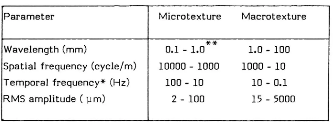
The choice of descriptor is governed by the data application and affects only the final phase of the laboratory data analysis system described later in this report. Typical values through which the descriptors range are listed in Table I, along with some comparable macrotexture values.
Further details are available in Dahir and Henry (1978) and Sandberg
(19841
Table 1 Microtexture and macrotexture
Parameter Microtexture Macrotexture
**
Wavelength (mm) 0.1 - 1.0 1.0 - 100 Spatial frequency (cycle/m) 10000 - 1000 1000 - 10 Temporal frequency* (Hz) 100 - 10 10 - 0.1
RMS amplitude ( um) 2 - 100 15 - 5000
* Apparent frequency when observed with a transducer traversing the
pavement at 10 mm/s.
** Limited range for this particular experiment
It may be observed that the values quantifying microtexture are gener-ally an order of magnitude smaller than the comparable macrotexture values. This imposes a substantialy greater demand on the instrumenta-tion system required to measure microtexture. Experience in macro-texture measurement (e.g. Sandberg 1984) has indicated that existing laser systems are generally not suited to microtexture measurement since they lack the requisite precision and resolution. However a new generation of laser instruments has become commercially available only recently. It is an intent of the present report to examine the feasibility of using these systems to measure microtexture.
2 EXPERIMENTAL TRIALS 2.1 Laser Equipment
A Remplir 'Precimeter' semiconductor laser (model DD-40-R6) was used for the trials. This is one of the new generation, short distance, precision measuring laser systems which, like their predecessors, provide distance
measurement via triangulation principles (Remplir 1980). It is compact
(82 mm x 69 mm x 25 mm), has a measuring range of 6 mm and is mounted 40 mm from this range. Importantly, the unit has a narrow beam of 1 mm diameter at exit from the laser with a spot size at the measurement surface of approximately 0.1 mm. Furthermore, Remplir quote linearity and accuracy figures of 40.2% respectively. By means of a simply fabricated adapter, the Remplir unit was readily mounted onto the VTI Stationary Laser Profilometer.
2.2 Instrumentation System
The instrumentation system adopted for the trials was that used previously for macrotexture measurements with the Stationary Laser Profilometer (Sandberg 1984 and 1986). Briefly, the Laser unit is mounted on a rig which provides a constant speed traverse over, at a fixed distance above, a pavement surface. Output signals from the laser transducer were both recorded on paper by anultra-Violet recorder and analyzed directly on a third octave band real time analyser (Brüel and
Kjaer Type 2131).
With this system, both the amplitude profile and frequency spectrum of suitable signals may be determined. After the straightforward setup and initial adjustments, clear, strong signals were received from the laser system. Both amplitude profiles and frequency spectra were readily
2.3 Trials
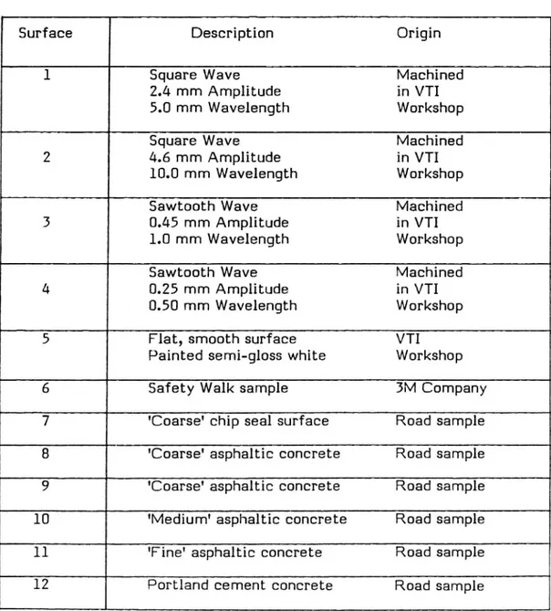
The experimental trials involved determining both amplitude profiles and frequency spectra for a range of surfaces. Chosen to test the capability of the system to measure microtexture, the surfaces are specified in Table II. Surfaces 1 and 2 are used in calibrating the existing VTI macrotexture profilometer. Similarly, Surfaces 3 and 4 were machined both for the present experiments and as possible future microtexture
calibration surfaces.
The painted Surface 5 was included as an attempt to provide a readily available, flat, smooth surface with which the instrumentation system background noise could be determined.
Table II Surfaces usedin trials
Surface Description Origin
l Square Wave Machined
2.4 mm Amplitude in VTI
5.0 mm Wavelength WorkshOp
Square Wave Machined
2 4.6 mm Amplitude in VTI
10.0 mm Wavelength Workshop
Sawtooth Wave Machined
3 0.45 mm Amplitude in VTI
1.0 mm Wavelength Workshop
Sawtooth Wave Machined
4 0.25 mm Amplitude in VTI
0.50 mm Wavelength Workshop
5 Flat, smooth surface VTI
Painted semi-gloss white Workshop
6 Safety Walk sample BM Company
7 'Coarse' chip seal surface Road sample 8 'Coarse' asphaltic concrete Road sample 9 'Coarse' asphaltic concrete Road sample 10 'Medium' asphaltic concrete Road sample 11 'Fine' asphaltic concrete Road sample 12 Portland cement concrete Road sample
Safety Walk (Surface 6) is a widely known material that is adhered in position to provide a 'non-Slip' surface for pedestrians. It has some application in laboratory drums for tyre testing. The remaining six surfaces are standard samples taken from roads in Sweden. They were selected for the present trials merely by inspection. It was reasonably anticipated that these samples would exhibit a typical range of Swedish microtextures. It was not, however, possible to obtain any independent, objective measure of the microtextures of these six surfaces.
2.4 Amplitude Profile Data
Amplitude profiles for all 12 surfaces are reproduced in Fig 1 from the u-v chart records. On first inspection it is apparent that the system has distinguished to some degree between the surfaces. Clean waveforms, generally as expected, have been obtained and these obviously vary with surface type. As also expected, only minimal output was obtained from the painted Surface 5. The signal for Surface 5 might thus be regarded as the instrumentation system background level. The macrotexture fluctua-tions are clearly apparent in the profiles of Surfaces 6 to 12. These are characterized by the longer wavelength, higher amplitude fluctuations in each profile. Microtexture, which is comprised of short wavelength, low
amplitude fluctuations (refer to Table I), is also visible in the Fig 1
profiles.
Good, well shaped square waves were obtained for Surfaces 1 and 2. Accuracy achieved in the reproduction of square wave signals is generally regarded as a critical test for most instrumentation systems of the type now under study. The square wave observations of Fig 1 suggest that the system has performed well in this regard. Also, the sawtooth Surfaces 3 and 4 have been reasonably well reproduced. In fact the sawtooth curves of Fig 1 provide good profiles of the actual surfaces, and this has been confirmed by examination of the actual surface profiles by means of an Optical projection microscope system. There are some flaws in these surfaces which resulted from the mechanical process of machining the surfaces.
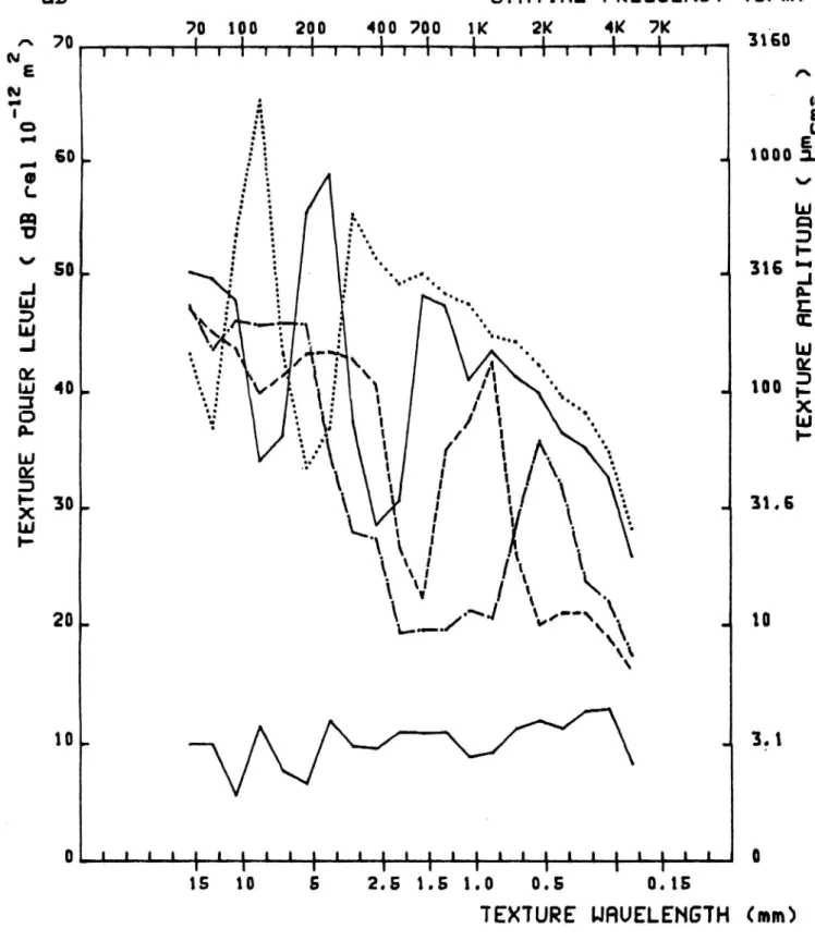
2.5 Frequency Spectral Data
Frequency spectra obtained for all surfaces are shown in Fig 2. Again it is apparent that the system has distinguished between the surfaces. The two square wave spectra are, as expected, of the same shape and differ only in level and location along the frequency axis. These differences correspond to the actual differences in magnitude and frequency between the two surfaces. Similar observations and comments apply to the spectra of the sawtooth Surfaces 3 and 4.
It should be noted that the spectral levels for the smooth, painted Surface 5 are somewhat lower than the other spectra. That is, the system background levels are sufficiently below the levels of the data of interest so as not to influence these data. However, there was some background noise in the system, and this occured in the frequency range 125 Hz to 8 kHz. The magnitude of this noise ranged from a minimum 15 dB at 125 Hz to a maximum 30 dB at 3.15 kHz. Although this was outside the measurement range of interest, as a precaution all output signals from the transducer were passed through a 60 Hz low pass filter prior to both amplitude profile plotting and spectral analysis. Note that
60Hz corresponds to 4.5 kc/m in Fig 2.
The spectra for the seven other surfaces exhibit some clear trends. In all cases, the lower frequency components, below around 750 c/m, contain information on the surface macrotextures. Note that this is why the fundamental peaks of the macrotexture profilometer calibration Surfaces 1 and 2 lie in the range below 750 c/rn. Returning to Surfaces 6 to 12, the spectra do indicate some marked differences in macrotexture and these are also apparent in the amplitude profiles of Fig 1 as mentioned previously.
Above the frequency of approximately 750 c/m, the higher frequency components suggest that there are some small, but quantifiable differ-ences in microtexture between the surfaces. The clear differdiffer-ences in the known Surfaces 3 and 4 at these frequencies indicate that the instrumen-tation system is capable of discrimination, at least, in the microtexture frequency range. This adds weight to the argument that the spectra of Surfaces 6 to 12 are close in the high frequency region because there
might be only small differences between the microtextures. It should be noted that the amplitudes of known Surfaces 3 and 4 are 450 and 25011 m respectively, while the microtexture amplitudes of Surfaces 6 to 11 would be expected to lie in the 2 to 12 pm range. As a consequence, some caution must be exercised when comparing the microtexture results from these two sets of surfaces. In future, perhaps more
appropriate calibration surfaces, such as that described by Brock (1983),
should be used.
3 ANALYSES AND INTERPRETATIONS 3.1 Known Surfaces
3.1.1 Amplitude Profiles
The amplitude profiles of Surfaces 1 to 4 can be applied both to calibra-tion of the instrumentacalibra-tion system and to a further examinacalibra-tion of the system performance. Calibration was required of both the vertical and
horizontal axes shown in Fig 1. For the texture amplitude (vertical axis)
this is simply achieved by determining the ratio of the heights of the four waves of Fig 1 to the corresponding, independently measured values of the actual surface heights. For the two square waves, this ratio turned out to be 0.061 mm/mm, while for the sawtooth waves it was 0.048 mm/mm. Such a discrepancy is consistent with a laser spot size of 0.2 mm. This is a reasonable figure, since Remplir (1986) suggest that, with careful focusing, a 0.1 mm spot size can be achieved at the mid-point of the meas'uring range. However, an 0.2 mm spot will have the effect of clipping the peaks and filling the troughs of the two sawtooth surfaces. Consequently, the system would under-estimate their ampli-tudes by around 20%, which was the discrepancy observed. It might be necessary to resolve this issue for future microtexture measurements, so that suitable calibration surfaces may be adopted. For the purposes of the present initial investigation, a factor of 0.061 mm/mm was selected. It was felt to be free of any such possible peak clipping/trough filling problem and would also allow ready correlation with previous calibration of the macrotexture profilometer.
Horizontal axis calibration of Fig 1 was simpler and merely involved relating the Ultra-Violet recorder paper speed to that of the laser transducer traverse speed. For a paper speed of 100 mm/s and a traverse
speed of 13.3 mm/s (nominally 10 mm/s), this gave a sample size to horizontal axis (Fig 1) ratio of 0.133 mm/mm.
In addition to the axis calibration, the square and sawtooth waves of
Fig 1 may be used to obtain a further estimate of the instrumentation
system performance. This was achieved by determining, for both the two square waves and the two sawtooth waves, the ratio of the peak heights and of the peak widths. Listed in Table III, these ratios are in good accord with these measured independently on the actual surfaces. That is, the system has demonstrated good potential in measuring both the absolute and the relative magnitudes of each of the two known surfaces. However, it should be noted again that the amplitudes of these two surfaces exceed those of typical microtexture.
Table III Peak Height and Width Ratios
Waveform Parameter Value obtained Value obtained from
ratio from Fig 1 independent measures
of actual surfaces
Square Wave Peak Height 0.52 0.52
Surface 1/Surface 2 Peak Width 0.54 0.50
Sawtooth Wave Peak Height 0.61 0.56
Surface 4/Surface 3 Peak Width 0.51 0.50
3.1.2 Frequency Spectra
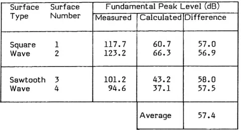
The spectra of Surfaces 1 to 4 may be applied for calibration purposes by comparing the spectral peak power levels determined by the system with appropriate calculated levels. For each of the four surfaces, routine Fourier analysis (Farison 1968) provides calculated spectral peak power levels. As shown in Table IV, this process gave consistent results when
applied, in accord with routine practice (Sandberg 1984), to the
adjustment of 57.4 dB was applied to the output of the Real Time Analyzer, thereby fixing the vertical axes of Fig 2.
Table IV Spectral Power Level Calibration
Surface Surface Fundamental Peak Level (dB) Type Number Measured Calculated Difference
Square l 117.7 60.7 57.0
Wave 2 123.2 66. 3 56.9 Sawtooth 3 101 . 2 43 . 2 58 . 0 Wave 4 94.6 37.1 57.5
Average 57.4
Some spectral comparisons were then possible in Fig 2, particularly for the spectra of Surfaces 1 to 4. Firstly, the power levels of the fundamen-tal peaks in the Surfaces 1 and 2 Spectra were compared, as similarly were the corresponding peaks in the Surfaces 3 and 4 spectra. These comparisons are documented in Table V, where again consistent results were obtained. It was found that, for both surface types (square wave and sawtooth), the measured differences in the fundamental peak power levels were in good agreement with the comparable calculated differ-ences. Although this observation partly reflects the calibration proce-dure of Table IV, it does serve to indicate the capability of the system to produce correct spectral components and levels.
10
Table V Spectral Peak Comparisons
Comparison Surface Spectral Power Level (dB)
Measured Calculated 1 60. 3 60. 7 2 65. 8 66. 3 Fundamental Difference -5. 5 -5. 6 Peak 3 43. 8 43. 2 4 37. 2 37. l Difference 6. 6 6. l 3rd 1 48. 1 51 . l Harmonic 2 55. 1 56. 8 Difference -7. 0 -5 . 7 1(Fund.) 60.3 60.7 Fundamental 1(3rd H.) 48. 1 51 . l -3rd Harmonic Difference 12. 2 9. 6 2(Fund.) 65.8 66.3 2(3rd H.) 55.1 56.8 Difference 10. 7 9. 5
This observation was supported by the comparison of the third harmonic peaks of the Surface 1 and 2 spectra which is also shown in Table V. Here, the measured difference in power level between the two third harmonic peaks closely aligns with the calculated value. Such a compari-son was not possible for the sawtooth Surfaces 3 and 4, since their third harmonic peaks were both low in level and barely detected by the instrumentation system. It should also be noted that each of the four measured spectra of Fig 2 are of the shape calculated in the Fourier Analysis. This analysis indicated that the spectra should contain odd harmonic peaks only, with the peak power levels decreasing with increas-ing harmonic number. Specifically, the analysis suggests that there is no second harmonic, and this was observed in each of the Fig 2 spectra. Consequently, in Table V, the measured and calculated relationships
between the first (fundamental) and third harmonics have also been
explored for Surfaces 1 and 2. Reasonably good agreement has been obtained between the measured and calculated differences, further con-firming the capability of the system to determine correct spectral shape
11
3.2 Sample Surfaces
As with the Known Surfaces, the spectra in Fig 2 for the Sample Surfaces clearly map the amplitude profiles of Fig 1. For example, the 3.8 kc/m peak in the Surface 8 spectrum is readily observed in the corresponding amplitude profile. (Here there are some 38 prominent peaks over a 10 mm distance in the profile.) Similar observations can be made in the other spectra and profiles. These routine observations merely confirm the performance of the instrumentation system in producing correlated frequency and space domain output.
Both the spectra and the profiles suggest that there are relatively small differences in microtexture between the sample surfaces. This has been discussed previously, and it is most likely that the observations indicate the real, but small microtexture differences between the surfaces. Alternatively there may be some instrumentation limitations, not revealed via the tests on the known surfaces, which have affected the results. These include variations in either the light spot size or the light intensity of the laser system. It was not possible to measure such factors in the current study, but further consideration of them should be
12
4 CONCLUSIONS AND RECOMMENDATIONS
Road surface microtexture occurs over wavelengths of up to 1 mm and thus spatial frequencies of down to 1000 cycle/m. The RMS amplitudes of the parameter range from 2 to 12 um. An initial investigation has indicated that it might be possible to use laser techniques to measure microtexture for wavelengths down to a minimum of 0.2 mm. The laser system trialed, with a measuring range of 6 mm and a spot size of around 0.1 to 0.2 mm, performed well in producing amplitude profiles and frequency spectra of known square wave and sawtooth wave surfaces. However, when applied to a series of typical Swedish road surfaces, the system indicated that there were some small, yet quantifiable differ-ences in microtextrue between the surfaces. Consequently, it was concluded that the feasibility of measuring road surface microtexture via laser system techniques had been demonstrated. Therefore it is recommended that work proceed to develop fully and evaluate sucha laser based microtexture measurement system.
Calibration of the laser system was achieved using known square and sawtooth wave surfaces. Of these, the latter provided signals within the frequency range but outside the amplitude range of road surface micro-texture. Thus it is recommended that the possibility of using calibration surfaces of lower amplitude be investigated. Furthermore, when attempting to measure the microtexture of road surface samples, it has not yet been possible to correlate the laser system outputs with some independent measures of microtexture. While this is largely due to the general lack of such techniqus, it is recommended that the possibility of adopting procedures of either the optical or mechanical type be investigated. In addition to possibly providing the necessary correlation data, such techniques might also greatly assist in calibration of the laser system. Finally, it is understood that there are other commercially avail-able laser systems, similar to the unit used in the present study, which may be suitable for microtexture measurement. The feasibility of using these systems for microtexture measurement should also be studied.
13
REFERENCES
Brock, M. (1983). Fourier analysis of Surface Roughness. Bruel and Kjaer Technical Review No 3, 1983. Brüel and Kjaer, Naerum, Denmark
Dahir, S.H. and Henry, 3.3. (1978). Alternatives for the optimisation of
aggregate and pavement properties related to friction and wear resist-ance. US Dept. of Transp., Report FHWA-RD-78-209.
Farison, 3.8. (1968). Applying Fourier techniques to signal analysis.
Instruments and Control Systems, Vol 41, March 1968, pp 99-120.
Magnusson, G., Sandberg, U. and Wenåll, J. (1985). The VTI Road Unevenness and Macrotexture Measuring Vehicle. VTI Notat.
Remplir (1986). Precimeter user's information. Remplir (Opto Electronics) AB, Stenkullen, Sweden.
Sandberg, U. (1984). Macrotexture measurements on replica road
surfaces fitted to a drum at Dunlop Ltd., Birmingham. VTI Interim Paper 842.
Sandberg, U. (1987). Road traffic noise - the influence of the road
surface and its Characterization. Accepted for publication in Applied Acoustics, 1987.
M
L 1 l l l l l l l I J 1 l l I I
O123k56789101112131lo15 DISTANCE (mm) Figure l Amplitude profiles
, SURFACE
1 SOUARE HAVE SOUARE HAVE 3 SAW TOOTH WAVE z, . SAW TOOTH WAVE S PAINTED 6 SAFETY WALK 7 CHIP SEAL1000pm'
l 1 441 l l J* 1 l l I J 1 l I J J
0 1 2 3 10 S 6 7 6 9 10 11 12 13 110 15
DISTANCE (mm)
Figure l Amplitude profiles
SURFACE 8 ASPHALTIC CONCRETE 9 ASPHALTIC CONCRE TE 10 ASPHALTIC CONCRETE 11 ASPHALTIC CONCRETE 12 PORTLAND CEHENT CONCRETE
)
TE
XT
UR
E
?O
UE
R
LE
UE
L
(
dB
va
l
10
'1
2m
2
0. m V o 6050
40 3020
10
SPHTIHL FREGUEHCY 701 100J 2001 400 7001 1 IK1 ?KJ 4kJ ?K1 _Tjjj7jv17jIjjj1111j11117jj1p
4
r å ä .... o- 4\
2 O
.\X\
°._. \-§
/'1 §\\ ,1'M'
0 :. v, \| III: .3. .lä
':1
z.5
.'i
1' 1/I 1
i.a
i'
,I
'. /\.
J
\
|
l ,{
1/ \
1/ \ y- \ 1 '| JL \ :
1 \ f
\
\-
\
\ \\I' I* \ 1 V I \\ F' \L.-.._./ \J \V/--\\ J \ .\\ \ Llll?1%LL%LL%1%L%II%1L%LFLL 15 10 5 2.5 1.5 1.0 0.5 0.15 TEXTURE UHUELENGTHSURFHCE NO.1 SGUHRE UHUE °°°°°°°°°°°°°°° "SURFHCE N0.2 SQUHRE UHUE --- "SURFHCE 0.3 SHUTOOTH URUE '-_ -m-"SURFRCE 0.4 SHUTOOTH UHUE SURFHCE 0.5 SHOOTH PHINTED
Figure 2 Frequency spectra
(c/m)
3150
D 1000316
100TE
XT
UR
E
HN
PL
IT
UD
E
<
pm
m,
31.510
3,1
(mm)
dB
70 100 200 400 700 IK ?K 4K ?K A 70 1 1 1 1 1 1 1 | 1 N I'WiiIñññññ11ñññññ111111j'ü E N | O .-0 U L Q 'UV 50
.
.J r / \ UJ / \\3
2/
\
LU \\ .J ; \\m
°
"
\
§3
lä
u\\\
\\
D- .: :° O"-m 3. 0....E 30
'. .J5 r'
\.
g... 20. J lor. .J OILLLLLILL lLLLlLlLLLLllllllI
I
r
1*
F*
I
SPHTIHL FREOUENCY (c/m)
- ---°- SURFHCE NO. 9
... ..5URFRCE N0.7 Figure 2 I 2:5 1.5 1.0 0.5 0.15TEXTURE HHUELENGTH
.
%
15 10
s
SHFETY URLK
CHIP SEHL
HSPHHLTIC CON.
RSPHRLTIC CDH.
SHOOWH PHINTED
SURFRCE 0.5
---SURFRCE N0.8
sunrnce 0.5
Frequency Spectre 3160 A P M S \000 E316
100TE
XT
UR
E
HN
PL
IT
UD
E
<
p
31.6
10
3.;
(mm)
dB
^7°TE
XT
UR
E
PO
UE
R
LE
UE
L
<
.13
,.,
1
10
":
m2
SPHTIHL FREOUENCY (c/m)
700 K 1 _' 400J 1 ?K 4k1 ?K1 1 1 1ñ1ññ1ñ1ñññ1 n o50
40 3020
10 jv'T Figure 2P
.1
p- .1,.
J
L 1 l l l 1 L L L LL L L LL l I L L L 1 L L 1 L 1 L 1 I T I F I I I I15 10
5
2.5 1.51.o
0.5
0.15
TEXTURE UHUELENGTH
SURFHCE N0.9 HSPHHLTIC CON.
SURFHCE N0.10 BSPHHLTIC CON.
SURFHCE N0.11 HSPHHLTIC CON.
SURFHCE N0.12 CEHENT CON.
SURFRCE ND.5 SHOOTH PHINTED
Frequency spectra 3160 1000