Eva Thorin
1, Jan Sandberg
1, and Jinyue Yan
1,2 1M¨alardalen University (MDH), V¨aster˚as, Sweden2Royal Institute of Technology (KTH), Stockholm, Sweden
1
INTRODUCTION
Combined heat and power (CHP) is the simultaneous produc-tion of useful heat and power in an integrated process with common fuel or energy source. Here, the basic principle and examples of processes based on using thermal energy for production of heat and power based on heat engines as well as fuel cell process are presented.
By integrating heat and power production, it is possible to use the energy source in a more efficient way and by that to reduce the environmental impact including CO2 emissions. One of the important factors to achieve efficient utilization of fuel in an energy system is to provide a demand for both heat and power. While producing electricity, the power plant can also supply heat for the heating demand of residential buildings in colder climates and/or industrial process heat.
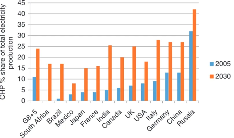
In 2008, the International Energy Agency (IEA) presented a report on the benefits of CHP investments and also some data on current installations. Figure 1 shows the contribution from CHP plants to the total electricity produced in the G8 and five more countries in 2005 and the potential for 2030 estimated by IEA. The total potential estimated is about twice as high in 2030 as utilized today (an increase from a share of 11% in 2005 to 24% in 2030). The report pointed out that CHP is a cost effective and important solution for reduction of CO2 emissions. In future, the study suggested that CHP has the potential to reduce CO2 emissions from new energy conversion installations in the world with 10% until 2030. Further, they also foresee a reduction in the investment costs, owing to lower investments in transmission and distribution Handbook of Clean Energy Systems, Online©2015 John Wiley & Sons, Ltd. This article is©2015 John Wiley & Sons, Ltd.
This article was published in the Handbook of Clean Energy Systems in 2015 by John Wiley & Sons, Ltd.
DOI: 10.1002/9781118991978.hces021
networks, which also, together with more efficient energy source utilization, can result in lower electricity prices for end consumers. (IEA, 2008).
An important trend is the development of technique and processes for small-scale and microscale CHP systems, while mature technique and processes for medium- and large-scale systems already exist. Among the mentioned reasons for developing small-scale systems are the possi-bility to more closely connect production and demand, better security of supply, better environmental regulation fulfillment, and more cost-efficient solutions. (Frederiksen, 2009; Liu, Shao, and Li, 2011; Moradi et al., 2013; Pade
et al., 2013).
Important research questions related to CHP are how to optimize the operation of CHP plants from an economic and environmental point of view. The development of new CHP energy systems is also conducted with multiple products, the so-called polygeneration with careful considerations of load demands. How to integrate renewable energy resources into the CHP plants is another important topic of interest.
2
BASIC PRINCIPLES OF
THERMODYNAMIC CYCLES OF CHP
The thermal energy processes used for CHP can be related to three types of processes, the Rankine or steam cycle, the Brayton or Joule cycle, and internal combustion engines. In the Rankine cycle, a circulating working fluid, usually water, passes through a four-step process. The steps for an ideal process are reversible, adiabatic compression; heat uptake at constant pressure (formation of steam); reversible, adiabatic expansion, and heat release at constant pressure. Power is produced in the expansion step and heat is produced in the heat release step. The Brayton cycle can be described with the same process steps as the Rankine cycle but with
0
G8+5 South Africa
BrazilMexicoJapanFranceIndia
Canada UK USA ItalyGermanyChinaRussia
5 10 15 20 25 30 35 40 45 CH P % share of total el ectri c it y producti o n 2005 2030
Figure 1. The share of the electricity production in the G8 plus five countries produced in CHP plants in 2005 and the potential estimated
for 2030. Source: Based on graphs reported in IEA, 2008.
the difference that the working fluid is a gas in all process steps. The Brayton cycle is often run as an open cycle without circulation of the working fluid. In this case air is compressed, a fuel is combusted in the compressed air, the flue gases are expanded and heat released by heat exchange before the flue gases are released to the surrounding air. In the internal combustion engine the working fluid is also a gas. However, in this process, all process steps take place in one process component—the engine cylinder. Two different cycle processes are common—the Otto cycle and the Diesel cycle. The ideal Otto cycle consists of reversible, adiabatic compression; heat uptake at constant volume; reversible, adiabatic expansion, and heat release at constant volume. In the ideal Diesel cycle, the heat uptake takes place at constant pressure instead of at constant volume. The Stirling engine is also of interest for CHP. Instead of heating the working fluid with internal combustion of a fuel this engine uses an external heat source but otherwise following the process steps of the ideal Otto cycle.
The fuel cell process is based on electrochemical energy conversion. The power from the process is produced by the electrons released in the electrochemical reactions and the heat produced comes from recovery of heat due to losses in the electrochemical process. This is then a major difference from the thermal-based processes where the heat release is a necessity for the power production.
The efficiency of a power cycle is usually described with the efficiency defined as the ratio of useful energy output and energy input. The thermal efficiency, also called power efficiency, for a power plant is defined as the ratio of the output of power (or work) and the heat input. For a CHP plant the useful energy output is both the power and the heat. It is therefore relevant to also use a total efficiency—the ratio
of the sum of output of power and heat and the heat input. The energy content of a fuel is usually described by its lower heating value (LHV), considering the water formed to be in the gaseous phase. In CHP plants, it is possible to increase the heat utilization by flue gas condensation. This results in that the total plant efficiency might reach more than 100% if the energy content of the fuel still is represented by the LHV. The size of a CHP plant can range from several hundreds of megawatts of fuel input to plants delivering heat for a district heating network of a whole city down to micro-CHP plants with energy inputs down to kilowatt level supplying a one-family house.
3
CHP SYSTEMS
The CHP system consists of the energy source, the energy conversion process, and demand side with the use of the produced heat and electricity. CHP plants can utilize many different types of energy sources. Fossil fuel and biomass-based energy sources can be used in all the above-mentioned types of processes. Nuclear power can also be used as a fuel for Rankine cycle-based processes even though it is not common for CHP applications. Waste heat from other processes can be utilized as the energy source in the thermal-based processes and also geothermal and solar heat can be used. The fuel cell process is also combined with hydrogen production from wind or solar power. Principally, that would be possible also for the thermal conversion processes. A large part of the solid biomass utilized for heat production in Europe is used in CHP plants (about 60% in 2011). Also a substantial part of the biogas (40% in 2011) used for power and heat production in Europe are used in CHP plants. (Eurobserver, 2012a,b).
The heat produced can be used for different heat demands, for example, a district heating network, an indi-vidual building, or industrial processes. Different types of conversion processes are possible for different applications and systems based on different conversion techniques are described in the following sections.
3.1 Steam turbine-based CHP
In a steam turbine plant for power production, the conditions for the heat release after expansion is designed for maximum power output, which means using as cold cooling water as possible giving a low pressure after the turbine. For a CHP plant the heat demand needs to be met and the pressure in the condenser is determined by the supply temperature for the district heating network. The balance between the output of power and the heat supply is an important parameter for the performance of the plant. This is described by the ratio between the electric power and the heat power (α-value). A lower heat supply temperature increases the power efficiency of the plant. When the heat sink is a district heating network the heat comfort of the customers is in focus. The heat demand of the customers is known to be depending mostly on outdoor temperature and human behavior (Gustafsson, Delsing, and Deventer, 2011; Dotzauer, 2002). To optimize the CHP plant performance, the heating load changes and variation with time of the district heating network are impor-tant (Starfelt et al., 2012a).
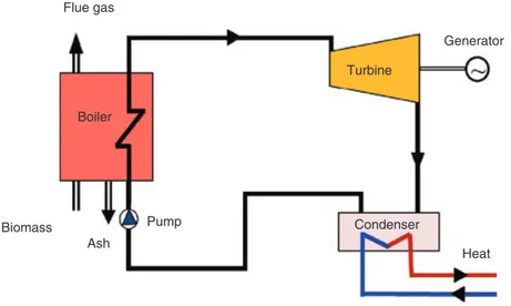
The principle of a (simple) steam turbine-based CHP plant is shown in Figure 2. In a CHP plant, the power production is completely dependent on the heat demand. If the heat demand is low the power production will also be low. There are some ways to increase the power production above what
is given by the heat demand (will be described later). The total efficiency of CHP plants will be around 90%. The losses are heat losses from the boiler and mechanical/electrical losses from the turbine/generator. The total efficiency is therefore not sufficient to describe the system performance of the CHP plant. Another performance indicator, called the α-value, is introduced in a CHP plant. For the same heat demand, a plant with a better (more advanced) turbine process will produce more electricity and have a higher α-value.
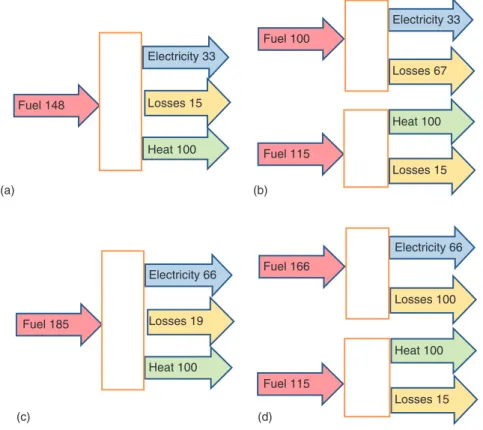
If a change of a certain parameter gives a higher thermal efficiency for a condensing power station, the same change will give a higher α-value for a CHP plant. A very simple plant with a steam pressure of 40 bar and a temperature of 450◦C at the turbine inlet will give an α-value of about 0.33 if the supply temperature to the district heating system is 80◦C. An advanced CHP plant with 180 bar and 540/540◦C (superheat/reheat), five stages of feed water heating and two condensers in series (65 and 80◦C forward temperatures) will give an α-value of about 0.66. It means that the advanced plant produces twice as much electrical power compared to the simple plant for the same heat demand. The higher the price of electricity the more advanced plant may be used. A comparison of different alternatives is shown in Figure 3. The heat production is the same in all four cases in the figure (100 units), and Figure 3a and 3c refers to the two cases with α-value of 0.33 and 0.66, respectively.
There are several opportunities to design a CHP steam plant to increase the power efficiency and the security of heat supply. Heat supply without running the steam turbine is possible when connecting the high pressure and low pressure sides with an expansion valve. The boiler and turbine can also be divided into several parts making it possible to run
Flue gas Biomass Boiler Pump Ash Heat Generator Turbine Condenser
(a) (b) (c) (d) Fuel 148 Fuel 185 Fuel 166 Fuel 115 Fuel 100 Fuel 115 Heat 100 Heat 100 Heat 100 Heat 100 Losses 15 Losses 19 Losses 15 Losses 15 Losses 100 Losses 67 Electricity 33 Electricity 66 Electricity 33 Electricity 66
Figure 3. The differences in conversion efficiency of CHP production compared to separate production of electricity and heat with (a) a
simple steam turbine-based combined power and heat plant, (b) separate production of electricity and heat (compared to simple combined power and heat production), (c) an advanced steam turbine-based combined power and heat plant, and (d) separate production of electricity and heat (compared to advanced combined power and heat production). The heat production is the same in all cases (100 units). Figure (a) and (c) shows the possible production of electricity in the combined cases producing 100 units of heat and the amount of fuel needed while (b) and (d) shows the corresponding need for fuel to produce the same amount of units of both electricity and heat in separate production plants.
part of the plant if another part fails. It is also possible to design the plant for higher power production than the heat demand admits. An additional turbine connected to a low temperature heat sink, without heat recovery, can be added. Other possibilities are to increase the steam flow in the CHP turbine by connection of a steam or hot water accumulator or the possibility to release part of the steam to the atmosphere (Wester, 2009).
Reheating is commonly used in steam turbine power plants to increase the power efficiency. However, with a high condensing pressure, as in CHP plants, the benefit is smaller and only economical for larger plants (Wester, 2009).
It is also possible to use other working fluids instead of water in a Rankine cycle-based CHP plant. The organic Rankine cycle (ORC) uses an organic substance as working fluid that makes it possible to use low temperature sources, for example, waste heat, geothermal heat, and solar heat, as the energy source. An example of a CHP concept utilizing the ORC technique is small-scale (0.4–1.2 MW produced electric power) plants with a biomass burned boiler heating
thermal oil that is used as the heat source for the ORC. Heat is produced both in the ORC condenser and with the flue gases from the boiler. There are also concepts using hot water instead of thermal oil. The ORC cycle can be operated at a lower pressure than a cycle with water as working fluid. These systems are mature and are commer-cially available. There are also examples of ORC-based CHP systems using solar heat as the energy source (Fred-eriksen, 2009; Liu, Shao, and Li, 2011; Tchanche et al., 2011).
The Kalina cycle, using a mixture of ammonia and water as working fluid, has also been investigated for CHP appli-cations (Dejfors, Thorin, and Svedberg, 1998).
3.2 Gas turbine-based CHP
The gas turbine cycle is one possible process for the so-called micro-CHP systems where power and heat are produced for small demands, for example, for one building or household, also called distributed generation.
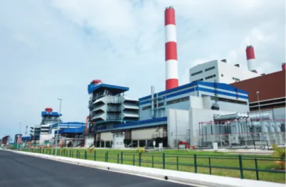
Figure 4. PowerSeraya’s completed cogeneration project at Jurong Island in Singapore. Source: Reproduced with permission.©Siemens AG.
Larger gas turbines can also be used combined with a steam turbine where the exhaust gases from the gas turbine produce superheated steam. This system is called combined
cycle and in Figure 4 an existing combined cycle is shown.
The steam is used in a CHP plant similar to those described earlier. The steam cycle is in this case called bottoming cycle as it uses heat from another power cycle, the gas turbine cycle, as energy source. In this case very high α-values (around 1.0) can be reached. If there is only demand for electricity and no heat demand for the CHP system, the gas turbine may be operated without the steam turbine that can produce about 2/3 of the output of electrical power. However, in the CHP with combined cycle, the steam turbine cannot be operated without heat demand.
Several advanced gas turbine CHP configurations are possible and have been studied, including evaporative gas turbine CHP plants (Yan, Eidensten, and Svedberg, 1994; Eidensten, Yan, and Svedberg, 1996; Jonsson and Yan, 2005). Gas turbine cogeneration can also be applied in different applications (Starfelt and Yan, 2008).
3.3 Engine-based CHP
For engines, heat can be extracted from the cooling system and also from the hot flue gases. Gas engines are common in CHP plants in the small-scale range (<10 MW electric power production). In this range, it shows higher power efficiencies than steam turbine-based CHP plants (α-value around 1.0). Engine-based systems are common for CHP based on biogas from anaerobic digestion. Gas from thermal gasification is another possible fuel. In Gˆussing, Austria, a CHP pilot plant with gasification of biomass and gas engine is run. (Frederiksen, 2009). Fuel Fuel Boiler Waste heat recovery Engine Electricity Heat Hot water Building Cooling Vapor compression system
Figure 5. An example of an engine-based CHP system for small
commercial buildings. Source: Reproduced with permission from
Mago, Chamra, and Hueffed, 2009.©John Wiley & Sons, Ltd.
Figure 5 shows an example of an engine-based CHP system for small commercial buildings. Here the engine is run to fulfill the electricity demand of the building including lighting, appliances, and equipment as well as cooling of the building with a vapor compression system. The waste heat of the engine is used for the heating and hot water demand of the building. In this case the system is designed to follow the electricity demand of the building and a boiler is needed to fulfill the heat demand. It would also be possible to design
the system based on the heat load but then the surplus of electricity produced needs to be possible to deliver to the electricity grid (Mago, Chamra, and Hueffed, 2009).
It is also possible to combine engines with bottoming cycles. One example is to use the Kalina cycle as a bottoming cycle. It has been shown that the potential for improving energy efficiency of engine-based systems through combined cycle can be significant (Jonsson, Thorin, and Svedberg, 1999; Jonsson and Yan, 2000a, 2000b, 2000c, 2001). 3.4 Fuel-cell based CHP
There are several different types of fuel cells with different electrolytes and different electrode reactions. The proton exchange membrane fuel cell (PEMFC), solid oxide fuel cell (SOFC), molten carbonate fuel cell (MCFC), and phosphoric acid fuel cells (PAFC) have all been used for CHP applica-tions. SOFC and MCFC are operated at high temperatures (800–1000◦C and 600–700◦C, respectively) and can also be used in combined cycles including a bottoming cycle. However, CHP based on fuel cells are mostly of interest for distributed generation and small-scale systems. Another advantage of the high temperature fuel cell, also impor-tant for small-scale systems, is the possibility for internal reforming of fuels making a fuel cell-based CHP system fuel flexible.
Micro-CHP based on fuel cells has been suggested to be a way to manage fluctuations in renewable energy supply by wind and solar power. However, to realize this solution the costs of the fuel cell technique needs to be reduced (Pade
et al., 2013; De Paepe, D’Herdt, and Mertens, 2006).
Pruitt, Bran, and Newman (2013), investigated the economic viability of an SOFC CHP system in a building, using natural gas as the fuel. They conclude that the costs need to be reduced to one-fifths of the current cost to make it economically viable. However, variability in utility energy pricing and different policy measures make the picture complex. They also point out the importance of balance between energy savings and carbon dioxide emissions, using fossil fuels.
On the homepage Fuel cells 2000 [www.fuelcells.org, managed by Breakthrough Technologies Institute (BTI), an independent, nonprofit, educational organization] a database with fuel cell installations all over the world, USA excluded, can be found. From 1990 to 2013, 611 installations for stationary fuel cells are presented. Of those almost one-third of the systems are CHP installations.
3.5 Polygeneration
In CHP plants using a district heating network as heat sink, the operating load is determined by the heat demand
in the network. As the heat demand usually varies during the year the full-load operating time of the production unit can be limited. An example is a steam turbine-based CHP plant for a Swedish small town where the full-load oper-ating time is as low as 10–20% of the year (Starfelt et al., 2012a, Starfelt et al., 2012b). By introducing other heat demanding processes as, for example, ethanol production and pellet production, in biomass-based CHP plants, the full-load operating time can be increased. The yearly production of electricity from biomass is then also increased. When evaluating the economic and environmental benefit of the polygeneration plant it is important to include the whole system, both the CHP plant and the heat demanding process. Optimal operation conditions can be different in polygener-ation plants compared to separated processes. Integrpolygener-ation of several processes can also give environmental benefits such as lower CO2 emissions compared to separated processes. Integrating ethanol production from straw in a CHP plant can be an efficient way to increase the utilization of straw for CHP production as the ethanol production residues has been found to be a higher quality fuel and easier to combust than the straw itself. The CHP can also be further improved by introducing biomass pellets production to improve the performance of operation in particular when heat demand is low. (Starfelt et al., 2010; Starfelt et al., 2012a, Starfelt et al., 2012b; Song et al., 2011; Wahlund, Yan, and Westermark, 2002).
4
APPLICATIONS
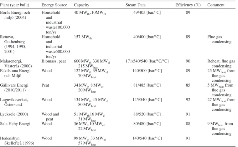
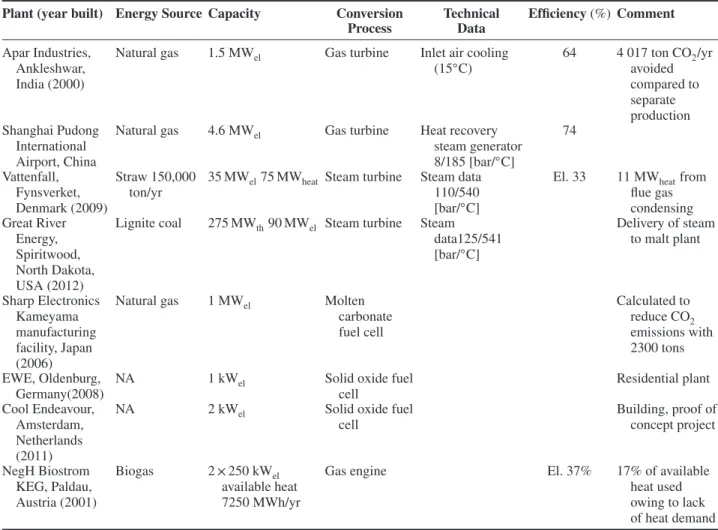
Sweden is an example of a country with cold climate where CHP production is widely used for covering part of the heat demand in buildings by district heating. Most plants are steam turbine based with biomass as fuel feedstock. Table 1 describes examples of existing CHP plants in Sweden and their characteristics. Examples of plants in other parts of the world are provided in Table 2. The examples also include other conversion processes than the steam turbine based and illustrate the range of sizes and variety of energy sources used.
The profitability of CHP plants depends not only on many different parameters such as energy prices, technology used, location and size but also on operational strategy. The oper-ational strategy can, for example, be to run the plant contin-uously, to follow the electricity demand, to follow the heat demand, and/or to include a heat storage option (Fragaki, Andersen, and Toke, 2008; Ghadimi, Kara, and Kornfeld, 2014; Taljan et al., 2012). Westner and Madlener (2011) compared different CHP technologies from a return and risk perspective using mean-variance portfolio theory for the
Table 1. Some examples of steam turbine-based CHP plants in Sweden.
Plant (year built) Energy Source Capacity Steam Data Efficiency (%) Comment
Bor˚as Energi och milj¨o (2004) Household and industrial waste100,000 ton/yr 40 MWth*10MWel 49/405 [bar/◦C] 89 Renova, Gothenburg (1994, 1995, 2001) Household and industrial waste500,000 ton/yr
157 MWth 40/400 [bar/◦C] 89 Flue gas
condensing
M¨alarenergi, V¨aster˚as (2000)
Biomass, peat 600 MWth330 MWel
215 MWheat
171/540/540 [bar/◦C/◦C] 90 Reheat, flue gas
condensing Eskilstuna Energi
och Milj¨o
Wood 122 MWth39 MWel
70 MWheat
140/500 [bar/◦C] 89 25 MWheatfrom
flue gas condensing G¨allivare Energi (2010/2011) Peat 34 MWth8 MWel 20 MWheat
81/485 [bar/◦C] 85 5 MWheatfrom
flue gas condensing Lugnviksverket, ¨ Ostersund Wood 134 MWth45 MWel 80 MWheat
145/540 [bar/◦C] 92 27 MWheatfrom
flue gas condensing
Lycksele (2000) Wood and
peat
51 MWth16 MWel
31 MWheat
88/520 [bar/◦C] 91
Sala Heby Energi Wood 36 MWth10 MWel
22 MWheat
80/480 [bar/◦C] 88 9 MWheatfrom
flue gas condensing Hedensbyn, Skellefte˚a (1996) Wood 99 MWth33 MWel 57 MWheat 140/540 [bar/◦C] 91
*th, thermal energy from combustion.
Source: Created using data from Johansson et al., 2009; M¨alarenergi, 2014; Wester, personal communication; G¨allivare Energi, 2014; Skellefte˚a Kraft, 2014.
German market. The technologies compared were large coal-fired CHP plants, combined-cycle gas turbine-based CHP (CCGT-CHP), engine-based CHP, and microturbine CHP. Their results show that combined-cycle gas turbine-based CHP and engine-based CHP give the best return, whereas the microturbine CHP shows the lowest risk exposure.
5
IMPLEMENTATION AND POLICY
INCENTIVES
Several barriers, related both to the market and regulations, exist for implementation of CHP, for example, lack of knowl-edge about the benefits of CHP, lack of integrated planning, lack of common methods to identify and quantify energy savings and environmental benefits and difficulties related to access to the electrical grid. Therefore policies are necessary to be able to develop the potential of CHP in the world (IEA, 2008).
The European Parliament and the Council of the European Union, decided on a directive (Directive 2004/8/EC) for
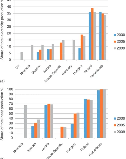
promotion of cogeneration of heat and power in 2004 with the aim to save energy and reduce greenhouse gas emissions. The tasks for the member states in the directive include analysis of the potential as well as ensuring support for CHP production and reporting the progress. Owing to the colder climate in the northern part of Europe, the member states in those parts have greater potentials for CHP production compared to the member states in the southern part. Figure 6 shows the reported progress for some of the membership countries. All countries do not report with the same detail. Besides the value reported for the share of the total electricity production provided by CHP in 2009, the German report also states an increase of 1.5% from 2002 (EU, 2013).
EPA, US Environmental Protection Agency, initiated a voluntary program called CHP partnership with the aim to promote the use of CHP in the United States. The program started in 2001 and supported development and investiga-tions of CHP by providing the partners in the program with information, tools, and platforms for establishing relation-ships (EPA, 2013). In the United States, several states have incentives for CHP in their climate policy plans.
Table 2. Examples of existing CHP plants in the world.
Plant (year built) Energy Source Capacity Conversion
Process Technical Data Efficiency(%) Comment Apar Industries, Ankleshwar, India (2000)
Natural gas 1.5 MWel Gas turbine Inlet air cooling
(15◦C) 64 4 017 ton CO2/yr avoided compared to separate production Shanghai Pudong International Airport, China
Natural gas 4.6 MWel Gas turbine Heat recovery
steam generator 8/185 [bar/◦C] 74 Vattenfall, Fynsverket, Denmark (2009) Straw 150,000 ton/yr
35 MWel75 MWheat Steam turbine Steam data
110/540
[bar/◦C]
El. 33 11 MWheatfrom
flue gas condensing Great River Energy, Spiritwood, North Dakota, USA (2012)
Lignite coal 275 MWth90 MWel Steam turbine Steam
data125/541 [bar/◦C] Delivery of steam to malt plant Sharp Electronics Kameyama manufacturing facility, Japan (2006)
Natural gas 1 MWel Molten
carbonate fuel cell Calculated to reduce CO2 emissions with 2300 tons EWE, Oldenburg, Germany(2008)
NA 1 kWel Solid oxide fuel
cell Residential plant Cool Endeavour, Amsterdam, Netherlands (2011)
NA 2 kWel Solid oxide fuel
cell Building, proof of concept project NegH Biostrom KEG, Paldau, Austria (2001) Biogas 2 × 250 kWel available heat 7250 MWh/yr
Gas engine El. 37% 17% of available
heat used owing to lack of heat demand Source: Created using data from IEA, 2008; Hinge, 2009; Babcock and Wilcox Power Generation Group, 2011; Sharp Electronics Corporation, 2013; Breakthrough Technology Institute, 2013; Amsterdam Smart City, 2014; Woess-Gallasch et al., 2011.
IEA, International Energy Agency, has analyzed different policies applied in the world for promotion of CHP and reported examples of different approaches with good results. IEA divides the possible measures into six different cate-gories “financial and fiscal support, utility supply obliga-tions, local infrastructure and heat planning, climate change mitigation, interconnection measures and capacity building” (IEA, International Energy Agency, 2008; IEA, 2009).
To improve the competitiveness of CHP plants in liber-alized electricity market, tools for optimization of the unit commitment and dispatch can be used. Both fulfillment of the heat demand and the possibility for trading electricity are then considered when planning the operation of the plant. Also the provision of secondary reserve can be considered. The development of optimization tools includes several different approaches, for example, linear programming, nonlinear programming, fuzzy programming, Lagrangian relaxation, and genetic algorithms (Thorin, Brand, and
Weber, 2005; Pirouti et al., 2011; Dvor´ak and Havel, 2013; Moradi et al., 2013).
6
CONCLUSION
CHP is a cost effective and important solution for reduction of CO2emissions and the potential for electricity production in CHP plants in the G8 and plus five countries (Brazil, China, India, Mexico, South Africa) has been estimated to be about twice as high as utilized today.
CHP plants can utilize many different energy sources such as fossil fuels, biomass, nuclear power, waste heat, geothermal energy, and solar energy. A large part of the solid biomass and biogas utilized for energy purposes in Europe are used in CHP plants.
The size of a CHP plant can range from several hundreds of megawatts of fuel input to plants delivering heat for a district heating net of a whole city down to micro-CHP plants with energy inputs down to kilowatt level supplying
(a) (b) 0 5 10 15 20 25 30 35 40 45 Share of total el ectri c it y producti o n % 2000 2005 2009 0 10 20 30 40 50 60 70 80 90 100 Share of total heat producti on % 2000 2005 2009 UK
Romania Sweden Austria
Slovak Republic
Germany Hungary Finland Netherlands
Romania Sweden Austria
Slovak Republic
Hungary Finland Netherlands
Figure 6. The development of the share of (a) electricity and (b) heat production provided by CHP in some EU membership countries.
Source: Reproduced from EU, 2013.
a one-family house. The most commonly used technique, for large-scale CHP plants, is the steam turbine process or the combined gas turbine and steam turbine process. Gas turbines, engines, and fuel cell processes are usually used for small-scale plants (<10 MW electric power produc-tion).
The α-value, the ratio between the output of power and the heat supply, is an important parameter for the performance of a combined power and heat plant. The higher the price of electricity the more advanced plant, with a higher α-value, may be used.
Incentives for promotion of combined power and heat production can be found in the world, for example, in Europe and the United States. Many approaches can also be found in the development of optimization tools for improving the competitiveness of CHP plants in liberalized electric power markets. Both fulfillment of the heat demand, the possibility for trading electric power, and the provision of secondary reserve are important to consider.
RELATED ARTICLES
Biomass for Polygeneration and District Heating
A Two-Phase Anaerobic Digestion Process for Biogas Production for Combined Heat and Power Generation for Remote Communities
Solar Water Heating
Direct Use of Geothermal Energy Geothermal Heat Pumps
Introduction: Clean Energy Conversion Technologies Steam Power Generation
Organic Rankine Cycles Including Fluid Selection Kalina Cycles for Power Generation
Gas/Steam Combined Cycles Fueled by Various Energy Sources for Large-Scale Power Production
Evaporative Gas Turbine (EvGT)/Humid Air Turbine (HAT) Cycles
Internal Combustion Engine (ICE) Fundamentals Solid Oxide Fuel Cell (SOFC)
Combined Cooling, Heating, and Power (CCHP) Systems Advanced Heat Exchangers for Clean and Sustainable Technology
NOxEmission and Mitigation Technologies
Energy Efficiency of Municipal Energy Systems: An Introduction
Energy Efficiency Improvement in Office Buildings by Benchmarking Models
Smart Cities
Energy-Efficient District Heating
Smart Homes as Integrated Living Environments Thermal Energy Efficiency in Industrial Processes Limits to Efficiency for Energy Utilization Seasonal Thermal Storage
Mobilized Thermal Energy Storage (M-TES) Technology for Industry Heat Recovery
Thermal Energy Storage for CSP Processes Cryogenic Energy Storage
Use of Thermal Mass in Building Energy Storage Thermal Energy Storage: Selection and Sizing Criteria Integration of Energy Storage into Energy Systems Introduction: Sustainability of Energy Systems Sustainability Assessment for Energy Technologies
Energy Efficiency Index via Data Envelopment Analysis (DEA): Methodology and Application
The Energy and Climate Policies of the European Union The Revealed Relationships between Energy Consumption and Economic Growth: Causality, Macroeconomics, New Trend, and Implications
Energy Security and Sustainable Development Opportuni-ties in Pacific Island Countries
Energy Consumption and Economy Development: An Empirical Case Study for China
Modeling Energy Efficiency and CO2Emissions Reduction Energy Efficiencies in ASEAN Region
REFERENCES
Amsterdam Smart City (2014) http://amsterdamsmartcity.com/ projects/ (accessed 14 October 2014).
Babcock & Wilcox Power Generation Group (2011) Great River
Energy Spiritwood Combined Heat and Power Plant, Plant Case History, http://www.babcock.com/library/Documents/pch579.pdf/
(accessed 14 October 2014).
Breakthrough Technology Institute (2013) http://www.fuelcells.org (accessed 14 October 2014).
Dejfors, C., Thorin, E., and Svedberg, G. (1998) Ammonia-water power cycles for direct-fired cogeneration applications. Energy
Conversion and Management, 39, 1675–1681.
Dotzauer, E. (2002) Simple model for prediction of loads in district-heating systems. Applied Energy, 73, 277–284.
Dvor´ak, M. and Havel, P. (2013) Combined heat and power production planning under liberalized market conditions. Applied
Thermal Engineering, 43, 163–173.
Eidensten, L., Yan, J., and Svedberg, G. (1996) Biomass Externally fired gas turbine cogeneration. Journal of Engineering for Gas
Turbines and Power , Transactions of ASME, 118, 604–609.
EPA (2013) Combined Heat and Power Partnership, http:// www.epa.gov/chp (accessed 14 October 2014).
Eurobserver (2012a) Solid Biomass Barometer, http://www.
eurobserv-er.org/downloads.asp (accessed 14 October 2014). Eurobserver (2012b) Biogas Barometer,
http://www.eurobserv-er.org/downloads.asp (accessed 14 October 2014). EU (2013) http://ec.europa.eu (accessed 14 October 2014).
Fragaki, A., Andersen, A.N., and Toke, D. (2008) Exploration of economical sizing of gas engine and thermal store for combined heat and power plants in the UK. Energy, 33, 1659–1670. Frederiksen, S. (2009) Sm˚askalig fj¨arrv¨armebaserad kraftv¨arme
(Small-scale district heating based combined heat and power).
Svensk Fj¨arrv¨arme AB. Rapport, 2009, 2 [in Swedish].
Ghadimi, P., Kara, S., and Kornfeld, B. (2014) The optimal selection of on-site CHP systems through integrated sizing and operational strategy. Applied Energy, 126, 38–46.
Gustafsson, J., Delsing, J., and Deventer, J.V. (2011) Experimental evaluation of radiator control based on primary supply temperature for district heating substations. Applied Energy, 88, 4945–4951. G¨allivare Energi (2014) http://www.gallivareenergi.se (accessed 14
October 2014).
Hinge, J. (2009) Elaboration of a Platform for Increasing Straw Combustion in Sweden, based on Danish Experiences. V¨armeforsk project no. E06-641.
IEA, International Energy Agency (2008) Combined Heat and
Power-Evaluating the Benefits of Greater Global Investment,
OECD/IEA, Paris.
IEA, International Energy Agency (2009) Cogeneration and District
Energy – Sustainable Energy Technologies for Today and Tomorrow, OECD/IEA, Paris.
Jonsson, M., Thorin, E., and Svedberg, G. (1999) Gas Engine Bottoming Cycles with Ammonia-Water Mixtures as Working Fluid, IJPGC’99 (International Joint Power Conference & Expo-sition), Burlingame, July 25–28.
Jonsson, M. and Yan, J. (2000a) Exergy and Pinch Analysis of
Diesel Engine Bottoming Cycles with Ammonia-Water Mixtures as Working—Part I: Assumptions and System Description, ECOS
2000, Enschede.
Jonsson, M. and Yan, J. (2000b) Exergy and Pinch Analysis of
Diesel Engine Bottoming Cycles with Ammonia-Water Mixtures as Working Fluid—Part II: Results and Discussion, ECOS 2000,
Enschede.
Jonsson, M. and Yan, J. (2000c) Exergy and pinch analysis of diesel engine bottoming cycles with ammonia-water mixtures as working fluid. International Journal of Applied Thermodynamics, 3, 57–71. Jonsson, M. and Yan, J. (2001) Ammonia-water bottoming cycles: a comparison between gas engine and gas diesel engines as prime movers. Energy, 26 (1), 31–44.
Jonsson, M. and Yan, J. (2005) Humidified gas turbine—a review of proposed and implemented cycles. Energy, 30, 1013–1078.
Johansson, A., Niklasson, F., Johnsson, A., et al. (2009) Drift och underh˚all av avfallsf¨orbr¨anningsanl¨aggningar—en j¨amf¨orelse av tv˚a tekniker och strategier (Operation and maintenance of waste combustion plant—development of a method for economical comparison of different techniques and strategies). WR-09, Waste Refinery [in Swedish].
Liu, H., Shao, Y., and Li, J. (2011) A biomass-fired micro-scale CHP system with organic Rankine cycle (ORC)—thermodynamic modelling studies. Biomass and Bioenergy, 35, 3985–3994. Mago, P.J., Chamra, L.M., and Hueffed, A. (2009) A review on
energy, economical, and environmental benefits of the use of CHP systems for small commercial buildings for the North American climate. International Journal of Energy Research, 33, 1252–1265.
Moradi, M.H., Hajinazari, M., Jamasb, S., and Paripour, M. (2013) An energy management system (EMS) strategy for combined heat and power (CHP) systems based on a hybrid optimization method employing fuzzy programming. Energy, 49, 86–101.
M¨alarenergi (2014) http:// www.malarenergi.se (accessed 14 October 2014).
Pirouti, M., Wu, J., Bagdanavicius, A., et al. (2011) Optimal opera-tion of biomass combined heat and power in a spot market. 2011 IEEE PES Trondheim PowerTech. The Power of Technology for a Sustainable Society. POWERTECH 2011, art. No. 6019322. Pade, L.L., Schr¨oder, S.T., M¨unster, M., et al. (2013) Policy schemes,
operational strategies and system integration of residential co-generation fuel cells. International Journal of Hydrogen Energy,
38, 3050–3063.
De Paepe, M., D’Herdt, P., and Mertens, D. (2006) Micro-CHP systems for residential applications. Energy Conversion and
Management, 47, 3435–3446.
Pruitt, K.A., Braun, R.J., and Newman, A.M. (2013) Establishing conditions for the economic viability of fuel cell-based, combined heat and power distributed generation systems. Applied Energy,
111, 904–920.
Siemens (2014) http://www.siemens.com/press/en/pressrelease/
?press=/en/pressrelease/2010/fossil_power_generation/efp2010 10005.htm (accessed 14 October 2014).
Song, H., Dotzauer, E., Thorin, E., and Yan, J. (2011) Annual perfor-mance analysis and comparison of pellet production integrated with an existing combined heat and power plant. Bioresource
Tech-nology, 102 (10), 6317–6325.
Sharp Electronics Corporation (2013) http://www.sharpusa.com.
Skellefte˚a Kraft (2014) http://www.skekraft.se.
Starfelt, F. and Yan, J. (2008) Case study of energy systems with a gas turbine cogeneration for an eco-industrial park. International
Journal of Energy Research, 32 (12), 1128–1135.
Starfelt, F., Thorin, E., Dotzauer, E., and Yan, J. (2010) Perfor-mance evaluation of adding ethanol production into an existing combined heat and power plant. Bioresource Technology, 101 (2), 613–618.
Starfelt, F., Tom´as Aparicio, E., Thorin, E., and Ericson, V. (2012a) Simultaneous dynamic and quasi-steady state simulations to opti-mize combined heat and power plant operation. International
Conference on Applied Energy, ICAE 2012, Suzhou.
Starfelt, F., Daianova, L., Yan, J., et al. (2012b) The impact of ligno-cellulosic ethanol yields in polygeneration with district heating—a case study. Applied Energy, 92, 791–799.
Taljan, G., Verbic, G., Pantos, M., et al. (2012) Optimal sizing of biomass-fired organic Rankine cycle CHP system with heat storage. Renewable Energy, 41, 29–38.
Thorin, E., Brand, H., and Weber, C. (2005) Long-term optimization of cogeneration systems in a competitive market environment.
Applied Energy, 81 (2), 152–169.
Tchanche, B.F., Lambrinos, G.R., Frangoudakis, A., and Papadakis, G. (2011) Low-grade heat conversion into power using organic Rankine cycles—a review of various applications. Renewable and
Sustainable Energy Reviews, 15, 3963–3979.
Wahlund, B., Yan, J., and Westermark, M.A. (2002) Total energy system of fuel upgrading by drying biomass feedstock for cogener-ation: a case study of Skellefte˚a bioenergy combine. Biomass and
Bioenergy, 23 (4), 271–281, 2002.
Wester, L. (2009) Kraftcykler (Power cycles). Teaching material [in Swedish].
Westner, G. and Madlener, R. (2011) Development of cogenera-tion in Germany: a mean-variance portfolio analysis of individual technology’s prospects in view of the new regulatory framework.
Energy, 36, 5301–5313.
Woess-Gallasch, S., Bird, N., Enzinger, P., et al. (2011) Greenhouse Gas Benefits of a Biogas Plant in Austria. IEA Bioenergy Task 38 Case Study Report.
Yan, J., Eidensten, L., and Svedberg, G. (1994) Parametric Anal-ysis of Biomass Externally Fired Gas Turbine Cogeneration, FLOWERS ’94, Florence, Italy.