http://www.diva-portal.org
This is the published version of a paper presented at 24th ISPE International Conference on
Transdisciplinary Engineering, Singapore, 10 July to 14 July, 2017..
Citation for the original published paper: Johansson, J., Elgh, F. (2017)
Automated Design Assessment as a Strategic Part of Design Platforms.
In: 24th ISPE International Conference on Transdisciplinary Engineering (TE2017):
Transdisciplinary Engineering: A Paradigm Shift (pp. 441-448). IOS Press
Advances in Transdisciplinary Engineering https://doi.org/10.3233/978-1-61499-779-5-441
N.B. When citing this work, cite the original published paper.
Open Access
Permanent link to this version:
Automated design assessment as a strategic
part of design platforms
Joel JOHANSSONa,1 and Fredrik ELGHb a,bMechanical Engineering, School of Engineering,
Jönköping University, Sweden
Abstract. This paper presents a general model for businesses to work with their
engineering assessments to challenge fluctuating requirements which is the result of a recently finished research project. The model is presented together with a case study of a company with a product that continuously is and must be adapted to a changing market to be alive at all. The company has developed a streamlined development process that is configured based on current needs from time to time. One keystone to make the mass customization possible to this company is the augmented synthesis and the automated assessment of the product variants rendered through the configured development process. The automated process of making the assessments and how it connects to the general model is also presented in the paper.
Keywords. Product platform, Product development, Customisation, Requirements,
Design Knowledge Reuse, Information Retrieval, Engineer-to-order, Engineering design, Traceability, Set-Based Concurrent Engineering (SBCE), Design Automation, Simulation-Based Design.
1. Introduction
Companies in industry maintain their competitive edge by continuously and systematically modularize and standardize their products. This is however a challenge for sub-suppliers due to the large difference between the various systems their products are to be integrated to, the markets the product are intended for, the use of the product and the customer’s individual preferences. These companies face the challenge of product requirements fluctuating in an unpredictable manner. The mass customization in such companies must be treated as a part of the development process putting focus on configuring engineering and manufacturing tasks rather than prefabricated components. Automation of manufacturing and production has been an ever-ongoing research activity for more than a hundred years making the automation of engineering tasks the bottleneck for achieving mass customization for companies facing unpredictably fluctuating product requirements.
This paper is organized as follows: First a frame of reference is provided to give a short brief of previous related work. Then a general model is presented for businesses to work with their engineering assessments to challenge fluctuating requirements. At end of the paper a case study of a company is described. The company manufactures a product that continuously is and must be adapted to a changing market to be alive at all.
The company has developed a streamlined development process that is configured based on current needs from time to time. Two keystones to make the mass customization possible to this company are the augmented synthesis and the automated assessment of the product variants rendered through the configured development process.
2. Frame of reference
Product development refers to a set of well-defined processes performed to transform market needs and opportunities into financial success for a company and its stakeholders [1]. The introduction of product platforms as a strategy for product development has made manufacturing companies more effective in meeting shifting market needs to a low cost. The driving force to develop product platforms is to reuse company assets which can mean anything from released components to more abstract descriptions containing knowledge, people and relationships. Two types of platform approaches were proposed by [2]: 1) Module based platform, constituted by a product architecture into which well-defined and often pre-manufactured modules can be assembled into a finished product. 2) Parametric platform, creates product family by introduction design parameters that are changed to specify product family members.
These two type of platforms requires the product to be at a high level of realization, i.e. the embodiment of all components is complete and can be configured or parametrically changed. This is far from true for many products and to overcome this problem a knowledge platform was proposed by [3]. A knowledge platform is built by reusable knowledge that is continuously gained through the different development processes.
Set-Based Concurrent Engineering (SBCE) is a lean product development method and is in this context an interesting mindset for product development. Opposed to a traditional point based approach it is instead encouraged in SBCE to develop sets of solutions in parallel [4]. In a point based approach a concept is chosen early in development and then iterated towards reaching a feasible solution. With SBCE on the other hand a wider spectrum in the design space is covered, making it more likely for the solution to be found. The focus is to eliminate unfeasible solutions when enough knowledge about the solution exist as opposed to early picking a solution when not enough knowledge exists. Positive effects when applying SBCE has been observed in industry [5]. Ward [6] summarises the benefits as: enabling reliable and efficient communication, allowing for greater parallelism in the process, basing the most critical decisions on data, promoting industrial learning and allowing for a search of globally optimal designs.
The knowledge value stream, aiming at capturing and reuse knowledge regarding markets, customers, technologies, product and manufacturing capabilities, is central in lean product development [7]. To make good use of the gained knowledge it should be generalised and visualised as far as possible to flow across projects and organisations. Knowledge can be of two kinds according to Kennedy [7]: First, we have knowledge that is conserved in people and secondly, we have knowledge that can be stored outside people. In the course of developing methods and tools for mass customization the knowledge of the latter one is utilized as far as possible.
3. Research method
This paper reports a research project entitled Challenge Fluctuating and Conflicting Requirements by Set-Based Engineering (ChaSE) that ran 2014 through 2016 aiming at understanding the challenges mentioned in the previous section and further to develop new methods for increasing the ability to efficiently develop and describe adaptive technology solutions to meet changing and conflicting requirements. Three large companies were engaged in the research project and served as testing areas for the ideas. This paper presents the final, general model in short and expands on one of the three case examples.
4. A general model for sub-contractors to work with their products to challenge fluctuating and contradicting requirements
As seen from the frame of reference manufacturing companies are encouraged to working with their products as platforms and with their knowledge in a structured way. There is however a need of a coherent platform model that support customization and easy adaptation to fluctuating and contradicting requirements during a development project, especially for companies with products not suited for pure configuration (that is based on prefabricated components). Through the research project of which this paper is reporting it has been shown that this ability can be gained by the following 10 actions [10]: 1) Define solutions as design spaces (continuous or discrete). 2) Generalize product structures. 3) Mapp existing solutions (components/assemblies) and projects. 4) Develop parametric geometry models. 5) Assess trade-offs. 6) Retrace, improve and publish engineering processes. 7) Define tasks with supporting methods and guidelines. 8) Build knowledge, skills and abilities (competence teams). 9) Improve by experience from product development. 10) Organize management of the platforms.
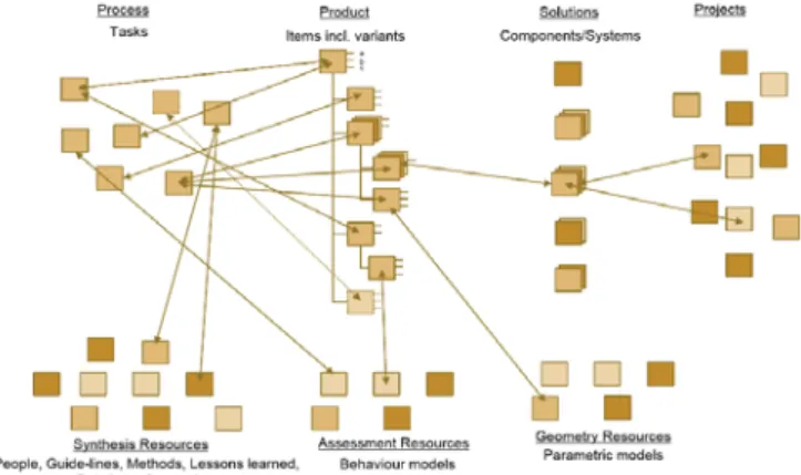
Figure 1. A model of the generic Design Platform. Arrows indicate associations in general.
The sum of the results from taking these actions is (when put together in a structured way) called a Design Platform, which is more abstract when compared to a product platform. The main theme in platform thinking is the reuse of components or
modules to keep the design effort efficient and at a manageable level. Design platform, even though more abstract and less tangible, supports continuous evolution and the reuse of knowledge and experience but also items used in previous projects.
A Design Platform is composed of different assets related to Process, Synthesis Resources, Product Constructs, Assessments Resources, Solutions and Projects (see Figure 1).
The Design Platform structure consists of Items (parts and sub-assemblies) at different levels of realization. Standard Items (Geometry) are components that are purchased or made to stock. These components are released to production and cannot be changed. Automated adaptable, flexible or tailor made Items (Geometry + Logics + Constraints) are components that are mathematically defined in CAD-models so that they can easily be changed and still have a sound geometry and be manufactured. Tasks to complete the embodiment for these parts are partly or fully defined. These components are normally developed and produced by the company. Non-automated adaptable, flexible or tailor made Items (Geometry + [Logics] + [Constraints], surrounding brackets indicates optional parts) are components that are mathematically defined in CAD-models so that they can be changed and still have a sound geometry [and be manufactured]. These components are developed and produced by the company. The logical model might not be complete. The constraints definitions on these models are normally scars. The focus is often on the adaptable geometrical model. Specialized or engineered Items (Logics [+ Constraints]) are components that are developed from time to time at the company but where the geometrical differences are that big that no general geometrical model can be developed. The focus is on developing the logical model, including tasks, and to some extent the constraints. When demanded the logics and tasks are configured into a process that is executed (manually, semi-automatically or automatically) to render the components.
During the development of the design platform the scope is extended to include the definition of a feasible design space of the underlying technology. These definitions include supporting documentation, methods, models and tools and is developed through or constituted by: 1) activities that govern the work of generating an adapted solution, 2) methods to define properties, 3) parametric CAD-models (constitutional models), 4) simulation ready behaviour models, 5) trade-off curves, 6) rules for controlling product constructs, 7) guide-lines for manual work, 8) structures for lessons learned and other supporting documents, and 9) expert support.
The Design Platform should be managed as an important asset and it should be able to evolve as knowledge is gained of its application in PD. Its completeness and the maturity of the different constituting parts should be continuously reviewed to ensure and improve the platform's usefulness.
5. Case study
One of the companies studied in the ChaSE research project and that we focus on in this paper, develops and manufactures products that support an active life style. Some of the products are transport centred, e.g. roof boxes and bike carriers, which makes car roof racks an important product to the company, which is product picked for the case study.
Both safety and geometrical requirements are put on the product, since it must be tightly mounted on the car roof so that it does not fall off in case of a crash, even if
loaded with several bicycles or a heavy roof box. Still the car body must not be damaged, buckled or scratched, when mounting the rack. These two strict and contradicting requirements set a very tight design space making it necessary to adapt the product for each new car model introduced on the market.
Since the company policy is to provide roof racks for 95% of all car models worldwide and due to the selling curve for peripheral car equipment peaks quickly after the release of the car model puts high pressure to make the adaptions of the roof rack product very quick (some few weeks). This together made it hard but still necessary to the company to develop a platform strategy. The trade-off was to make a design platform, that is a product platform with components not yet embodied but with processes and resources to do so when needed (see section 4). We will look at the company’s adaption process and resources to synthesis and analyse new variants of roof racks at high speed. Each of the subsection correspond to one category in the general model presented in Figure 1.
5.1. Product structure
What the customer really buys when buying a roof rack is the ability to carry load on the roof. To achieve that two bars are supported by four feet which in turn are mounted on the car roof. There are several types of roof/rack interfaces: rails, flush rails, fix points and clamping (for cars with no rails at all). It is the latter type, clamp racks, that was selected for the case study.
The strategy when developing the design platform was to embody as many components as possible and isolate the upcoming changes to just two components. The adaption is hence done by changing two components, the bracket and the foot pad. The foot pad is a rubber pad on which the rack is standing on the roof, and the bracket is used to fix the rack by keeping around the roof end where the doors are.
High requirements are put on these two components, especially the bracket, to keep the rack on the roof in case of a crash but still not buckle the car body when mounting the rack. The company acts on the open market competing with car manufacturers and therefore can get no nominal data of car roofs. Instead they must collect geometrical information about the car roofs using a scanner.
When the roof geometry is collected for one particular car model a foot-pad is selected or developed and the rack is placed on the foot-pad in the CAD-model. Finally, a bracket is selected or developed and mounted into the CAD-model. It can be concluded that there are three components in the product structure that cannot be predefined. The roof, the foot pad and the bracket.
5.2. Adaption process
The process of adapting the roof rack to a new car model is a streamlined development processes with four gates: Start up, Tool Release, Product Release, Project Closure. The scoping step includes market analysis and project budget specification. Then the roof of the car model to adapt the product to is scanned (since the company works on the open market they cannot get CAD-data from car manufactures since they are their competitors). The roof data is used to try to find existing foot pads and brackets that can be used to clamp the rack of the new car model. If there are no existing foot pads or brackets applicable new ones are developed. A set of standardized crash scenarios are simulated to make sure the roof rack is safe. If it is safe and existing components were
found to use, then the project is finalized by updating the standardized packaging and mounting instructions. If there are no existing components applicable to the new car roof, then new brackets and foot pads must be developed and in turn tooling must be developed, manufactured and tested. The process is configured and managed by a semi-automated spread sheet where the manager selects what process steps must be taken and who is responsible. When tasks are completed emails are autogenerated from the spread sheet to inform managers and initiate downstream activities.
5.3. Synthesizing of variants
Reusing components can make big short cuts in the adaption process. In fact, four process steps can be cut in such cases. These process steps consume up to 50% of the maximal project time and can make a project unprofitable. Previously this save in time was not obvious to engineers in the early steps to whom it was easier to develop new components rather than searching for existing ones (the CAD-models are not so complicated and the number of existing components to search is big). Case Based Reasoning (CBR) was applied to make it easier to retrieve existing brackets and footpads [11,12]. The CBR system was integrated to the CAD-system to interactively indicate search criteria and to visualise results in context of the CAD-assembly.
5.4. Assessing variants
The roof rack product is a safety component and it is hence necessary to assess each new product variant through testing. Since the company policy is to provide roof racks for 95% of all car models worldwide the testing cost is extensive, which calls for virtual testing. One problem with virtual testing through FEM-simulations in this case is the extremely short project lead-time (some few weeks from a car entering the market to launching the roof rack production). Therefore, it was necessary to automate the virtual testing process, a task that was adopted as a case study in the ChaSE research project.
Full functioning prototype software, under the workname AutoCRASH, was developed during the research project to make it possible to flexibly automate the process of transforming the roof rack CAD-models to crash simulation models. The software includes automated methods and processes performed in Solidworks (CAD-software), Ansa (pre-processor) and LS-Dyna (post-processor). The system is based on programmable features in the CAD-system [13], which is a more general type of feature than user-defined-features. The AutoCRASH features carry geometrical data as well as numerical and textual data and are used as a base for the transformation from CAD-model to crash simulation model. This method can be viewed as having the simulation model stored within the model, making it a simulation ready CAD-model. When making the transformation the AutoCRASH-features are interpreted into a python script executed in ANSA to render a LSDYNA model that can be executed. The script includes meshing commands based on pre-defined meshing and mesh quality parameters, material definitions, component interdependencies (such as contacts, joints, and constrained rigid bodies), boundary conditions and simulation execution preferences (such as reporting frequency, and execution time).
Once the model has been defined the user can create the FE-model by a single click in the menu-bar.
5.5. Geometry resources
One share of the ChaSE-model in Figure 1 is geometry resources and in the studied company these includes CAD-models of the foot, foot pads, brackets and roofs. The geometrical resources are not limited to CAD-models but also includes light-weight representations of roofs, foot pads, and brackets used when geometrically searching for existing components to reuse. Further there are geometrical models to support crash simulations which are pre-meshed components of the foot that are reused in every crash simulation. (Components that are unique for a simulation are automatically meshed by the AutoCRASH software.) Standard geometrical models of tooling for new brackets and foot pads can also be included in the category of geometrical resources.
5.6. Solutions
In this specific case, the roof rack product, solutions and car models are mapped one to one. In everyday language, the engineers indeed say they “solve a car”. What is most important to share as solution between projects is light-weight geometrical information regarding the brackets and foot pads. This information is collected during the follow up process. The information is collected by selecting certain features of the CAD-models which are interpreted and indexed to be searchable by the geometrical search engine. 5.7. Projects
Components checked in to the PDM-system include the foot, brackets and foot pads. But during a project there are more information than so. A project folder contains a CAD-model of the car roof with the roof rack mounted on top of it with brackets and foot pads (only one side of the car as the model is symmetric). The project folder also contains budget information, a local copy of a semi-automated spread sheet with the process and, crash simulations.
5.8. Supporting Set-Based Concurrent Engineering
Two resources make it affordable to introduce set-based concurrent engineering at the studied company. It is the geometrical search engine and the automated crash simulations. When having these tools at hand it is possible to select sets of candidate solutions (foot pads and brackets) and automatically execute crash simulations for each combination of these to develop trade-off curves to make decision of which one to select.
6. Conclusions
This paper summarizes one of the case studies in the research project entitled Challenge Fluctuating and Conflicting Requirements by Set-Based Engineering (ChaSE). The case study was performed at a company that develops and manufactures car roof racks to the open market. The company actively works with their products to develop design platforms (that are more abstract than product platforms) by introducing standardized workflows that can be configured for each project, automating parts of the
processes and storing solutions to reuse in new projects. This way of working has enabled the company to work in a set-based way and standing strong on the global market.
Acknowledgements
The authors express their gratitude to Thule Group for technical corporation and Vinnova Foundation for financial supports.
References
[1] H.C.M. León, and J.A. Farris, Lean product development research: Current state and future directions, EMJ - Eng. Manag. J. 23 (2011).
[2] T.W. Simpson, Z. Siddique, and J.R. Jiao, Platform-Based Product Family Development, in: T.W. Simpson, Z. Siddique, and J.R. Jiao (Eds.), Prod. Platf. Prod. Fam. Des. Methods Appl., Springer US, Boston, MA, 2006.
[3] H. Johannesson, Emphasizing reuse of generic assets through integrated product and production
system development platforms,Springer, New York, 2014.
[4] D.K. Sobek, A.C. Ward, and J.K. Liker, Toyota’s principles of set-based concurrent engineering,
Sloan Manage. Rev. 40 (1999) 67–84.
[5] D. Raudberget, and S. Sunnersjö, Experiences of set based concurrent engineering in four product developing companies, in: Proc. 8th Int. Symp. Tools Methods Compet. Eng. TMCE 2010, 2010. [6] A. Ward, J.K. Liker, J.J. Cristiano, and D.K. Sobek II, The second Toyota paradox: How delaying
decisions can make better cars faster, Sloan Manage. Rev. 36 (1995) 43–61.
[7] M. Kennedy, K. Harmon, and E. Minnock, Ready, Set, Dominate: Implement Toyota’s Set-Based Learning for Developing Products and Nobody Can Catch You, Oaklea Press, 2008.
[8] L.T.M. Blessing, and A. Chakrabarti, DRM, A Design Reseach Methodology, Springer, 2009. [9] R. Stolt, S. André, F. Elgh, J. Johansson, and M. Poorkiany, Managing Risk in the Introduction of
New Technology in Products, J. Aerosp. Oper. 3 (2015) 167–184.
[10] F. Elgh, S. André, J. Johansson, and R. Stolt, Design Platform : Setting the Scope and Introducing the Concept, in: Proc. Des. 2016 14th Int. Des. Conf. Dubrovnik, May 16-19, 2016. , The Design Society, Jönköping University, JTH. Research area Product Development - Computer supported engineering design, 2016: pp. 1253–1264.
[11] J. Johansson, and M. Cederfeldt, Interactive case based reasoning through visual representation - Supporting the reuse of components in variant-rich products, in: Proc. Int. Des. Conf. Des., 2012: pp. 1477–1484.
[12] J. Johansson, Combining Case Based Reasoning and Shape Matching Based on Clearance Analyzes to Support the Reuse of Components, in: Vol. 3 38th Des. Autom. Conf. Parts A B, ASME, 2012: p. 603.
[13] J. Johansson, A Feature and Script Based Integration of CAD and FEA to Support Design of Variant Rich Products, Comput. Aided. Des. Appl. 11 (2014) 552–559.