Blind swimmer detection and
notification utilizing OpenCV on
the Android platform
Samuel Zetterlund
Mälardalen University, IDT
Supervisor: Professor Lars Asplund
Abstract
For a blind swimmer to be able to exercise in a swimming pool today, human assistance is required to notifying the swimmer in due time when and if she is too close to the edge. The purpose of this thesis was to see whether or not it is possible to replace and even improve the human intervention using a warning system built around a tablet mounted next to the pool edge. A secondary goal was to evaluate how suitable a tablet pc is for robotic applications. The system proposed utilizes a tablet’s built-in frontal facing camera, OpenCV as vision library, FM modules for the wireless warning system and is intended for the Android environment.
Videos of the real scenario have been analyzed on a computer using OpenCV and a detection algorithm searching for the swimmer’s red swimming cap has been developed. Next, the algorithm was implemented on an Android tablet. The result obtained shows that it is perfectly possible to use a cheap tablet to accurately detect and notify the blind swimmer in due time when she is too close to the edge. If calibrated thoroughly, the likelihood of a missed detection is actually lower with this system as compared to human intervention, as humans can only warn the swimmer when she is above the water.
Abstract
För att en blind simmare ska kunna träna i en simbassäng krävs idag män-sklig assistans för att uppmärksamma utövaren i rätt tid när och om hon är för nära poolkanten. Detta exjobb har haft till uppgift att se huruvida det är möjligt att ersätta och även förbättra det mänskliga ingripandet med hjälp av ett varningssystem byggt kring en surfplatta monterad invid poolkanten. Ett sekundärt mål var att utvärdera hur lämplig en surfplatta är för robotikapp-likationer. Systemet som föreslagits använder en surfplattas inbyggda främre kamera, OpenCV som visionbibliotek, FM-moduler till varningssystemet och är avsett för Android-miljön.
Videor av det verkliga scenariot har analyserats på en dator med OpenCV och en detekteringsalgoritm som letar efter simmarens röda badmössa har tagits fram. Algoritmen har sedan implementerats på en Android-platta. Resultatet som fåtts visar att det mycket väl går att använda en billig surfplatta för att med god precision detektera och varna den blinda simmaren i rätt tid när hon är för nära kanten. Om en noggrann kalibrering gjorts så är faktiskt sannolikheten för en missad detektion lägre med detta system jämfört med det mänskliga ingripandet, då människan endast kan varna simmaren när hon är ovanför vat-tenytan.
Contents
1 Introduction 4
1.1 Introduction . . . 4
1.2 Problem statement . . . 4
1.2.1 OpenCV program on the Android platform . . . 6
1.2.2 Detection of human in water . . . 6
1.2.3 Wireless notification to swimmer . . . 6
2 State of the art 7 2.1 OpenCV program on the Android platform . . . 7
2.1.1 Ada/C/C++ as console application on Android . . . 7
2.1.2 Other Linux distribution . . . 8
2.1.3 Traditional app . . . 8
2.2 Detection of human in water . . . 8
2.3 Wireless notification to swimmer . . . 9
3 Method 11 3.1 Requirements . . . 11
3.2 Choice of platform . . . 11
3.3 Software . . . 12
3.3.1 Choice of method . . . 12
3.3.2 Lucas-Kanade optical flow . . . 12
3.3.3 Color thresholding with object estimation . . . 13
3.3.4 Fail safe . . . 20
3.4 Hardware . . . 20
3.4.1 Soundwave triggered system (non-OTG devices) . . . 20
3.4.2 Serially triggered system (OTG devices) . . . 21
3.4.3 PT2264/PT2294 encoder/decoder . . . 23
3.4.4 Vibration motor . . . 23
3.4.5 Summary of the complete circuits . . . 24
4 Experiments and results 26 4.1 Wireless transmission time lag and robustness . . . 26
4.1.1 Soundwave triggered system time lag . . . 26
4.1.2 Serially triggered system time lag . . . 27
4.1.3 Robustness to turbulence . . . 27
4.2 Comparison between the proposed algorithm and the reference stick with 10, 12 and’ 15 fps . . . 28
CONTENTS 3
5 Conclusions and discussion 33
5.1 FM transmission . . . 33
5.2 Placement of the camera . . . 34
5.3 Performance measuring . . . 34
5.4 Summary . . . 35
6 Future work 37 Bibliography 37 A Terms and OpenCV installation on Mac OS 40 A.1 Technical terms and terminology . . . 40
A.2 Rooting the tablet . . . 41
A.3 Getting started with Android on Mac OS X 10.8.2 Mountain Lion 42 A.4 OpenCV on Mac . . . 42
A.5 Compiling and cross-compiling for ARM . . . 42
A.5.1 Compiling on the target machine . . . 43
A.5.2 Cross-compiling for the target machine . . . 43
B Android application 44 B.1 Running mode . . . 44
B.2 Settings mode . . . 48
B.2.1 Color thresholding calibration procedure . . . 48
B.2.2 Updating of estimate values and other variables . . . 48
1
|
Introduction
1.1
Introduction
Vision systems often consist of many separate modules. Some sort of camera is needed for tracking the object and to process the images, a computer or such is essential. To effectuate the outcome of the image processing, actuators are needed and a screen, depending on the task, might also be required. Combining these modules can sometimes be a somewhat troublesome and pricey task. The latest years boom of tablet computers in terms of cost and performance makes it interesting to see how suitable they are for robotic applications since they already have the modules well integrated on the same platform.
The purpose with this project is to develop a vision system on a tablet computer running Android. All new Android systems are equipped with one, two or sometimes even three cameras in addition to powerful hardware and many of them also have support for communication with external devices using USB On-The-Go.
This master thesis should particularly look at the pros and cons of using a tablet as the major processing system for robotics applications. Programming of apps for Android tablets and smart phones are normally performed using the tools supported by Google. The underlying operating system is however based on Linux, which should enable the full power of normal programming tools. Therefore, a comparison between different programming approaches have been made to determine the best approach with respect to speed, simplicity and re-usability using OpenCV as vision library.
OpenCV is a constantly maintained open source library with over 500 func-tions. In this application it has been used to especially track humans with their respective speed and position. The application also require wireless communica-tion to notify the tracked human which have been considered and implemented. The system should also be ”fail safe” meaning it should not be possible to either stop the application or to launch any other application in the tablet.
A user guide covering how to set up a working Android development envi-ronment on a computer running Mac OS X 10.8.2 Mountain Lion as well as an overview of the Android application are found in the appendices.
1.2
Problem statement
The goal with this master thesis was to develop a system on the Android plat-form which can detect a swimmer in a swimming pool and determine when she
CHAPTER 1. INTRODUCTION 5
is within a certain distance from the pool edge with high precision. This system has been developed with particularly two implementations in mind:
1. To detect and notify a blind swimmer when she approaches the edge to remove the need of a human assistant.
2. Distinguish between swimmers performing regular exercise and to keep track of their lap times etc.
The main focus of this thesis is however the first implementation: the detec-tion of a blind swimmer. In all blind swimmer training contexts as well as in major competitions such as the Paralympics, officials equipped with a long stick with a soft cape dab the head of the swimmer and thus warn her, preventing her to swim into the wall. A disadvantage of this method is that the officials can only warn swimmers when they are above the water which can sometimes lead to swimmers ending up very close to the edge before getting notified. The idea of the warning system built during this thesis was to replace and even improve the intervention from the officials, making the warning more accurate. Warn-ings usually occur when the swimmer is at a distance of about 2-3 meters from the edge.
The blind swimmer should be notified when she is at a desired distance from the wall by a sound or vibration in some way.
Figure 1.1: Tablet and its camera placement
CHAPTER 1. INTRODUCTION 6
Figure 1.3: Warning signal has reached the swimmer
This overall problem can be divided into three subtasks explained in the following subsections.
1.2.1
OpenCV program on the Android platform
As mentioned in the introduction, Android is based on Linux which raises the question if it’s possible and/or a good idea to use conventional Linux program-ming tools instead of the ones given by Google. Making a program utilizing the OpenCV library to run smoothly on the tablet was the fundamental task regard-less the choice of underlying OS. The application should be fail safe meaning that no other applications should be allowed to run on the tablet making the system robust against any user interference.
1.2.2
Detection of human in water
Detecting humans with a camera is quite a popular topic where many differ-ent approaches can be taken. However, the placemdiffer-ent of the camera in this implementation as well as an extremely changing background and foreground (splashes and when the swimmer is beneath the surface) makes this problem the most difficult to solve.
1.2.3
Wireless notification to swimmer
It is crucial that the blind swimmer is notified at the right time to avoid any kind of injuries. The wireless communication therefore needs to be foolproof and the receiver device needs to be resistant to water and easily mountable on the swimmer.
2
|
State of the art
In this chapter, the state of the art in the areas of the problems stated in the previous chapter will be presented. For an explanation of the technical terms in this chapter, see A.1.
2.1
OpenCV program on the Android platform
The Android OS utilizes a virtual machine called Dalvik. In 2011, Lin et. al. [12] conducted 12 test programs to analyze the performance of Dalvik Java code compared to embedded native code through the Java Native Interface (JNI) and their result showed that the native code was about 34.2% faster in average. With this in mind, it’s reasonable to evaluate how feasible it is to completely disregard Dalvik Java code and run a console application instead. The following three options will be discussed:
1. Pure Ada/C/C++ code as a console application on the tablet.
2. Replacing Android with some other Linux distribution such as Debian or Ubuntu to more easily unleash the power of the underlying Linux system. 3. Traditional app and embed native code through JNI.
2.1.1
Ada/C/C++ as console application on Android
The first idea was to use Ada as programming language because it is a strongly typed language and very reliable. In 2011, Ada bindings for the C version of OpenCV were designed by Cederholm and Pettersson [13]. However, documen-tation of how to interface Ada with Android is poor. In 2010, The enthusiast Rob Veenker [1] published a guide on his website of how to create an application running native Ada code on Android using a native compiler made by another enthusiast called John Marino [4] but no official documentation or examples seem to exist.
On the contrary, much documentation and examples can be found where C and C++ programs can be cross-compiled easily to for example ARM ar-chitectures running Android. C4droid is an app available on the Google play, the market for all Android apps, which is a C/C++ compiler made for ARM processors. The latest GNU Compiler Collection (GCC) plugin available (which was updated on March 23, 2013) is the 4.7.2 version. By installing the C4droid app on a tablet with the ARM architecture, C/C++ programs can be written
CHAPTER 2. STATE OF THE ART 8
and compiled directly on the tablet using the supplied Integrated Development Environment (IDE), or be transferred to the tablet and thereafter compiled.
Figure 2.1: Tools for compiling C/C++ programs on the tablet The second alternative is to use a cross-compiler for the target platform. In June 2009, Google announced the Android 1.5 Native Development Kit (NDK) [3] which enables the ability to call native code from within an Android applica-tion. Nowadays, the toolset also supplies a method to use the Android toolchain as a standalone compiler [2]. Using this compiler, it’s possible to cross-compile programs for the Android platform utilizing the OpenCV library.
2.1.2
Other Linux distribution
It’s also possible to install other Linux distributions on an Android tablet. Nu-merous guides exist covering how to run a virtual instance of for example Debian or Ubuntu on top of Android. However, in the performance aspect, this option is not to be considered. Instead, Android could be completely replaced by an-other distribution but there is a severe risk of breaking the device connected to this and with the official Ubuntu tablet just around the corner [8] it might be a better choice to wait. This would also be better in the scaling aspect as it is time consuming to make too many modifications to the tablet if one wishes to mass-produce the product.
2.1.3
Traditional app
Making a traditional app is of no groundbreaking character. In april 2013, there were about 900 000 apps available for download on the Google Play market. [5]. A search for OpenCV on May 6, 2013 yielded about 100 relevant results. Of the nearly 3.5 million items available on the IEEE Xplore webpage, about 3 articles are listed where the authors utilize the OpenCV library on Android when searching for ”opencv android”. This gives an indication of how widely it’s used on the Android platform. However, good documentation and example programs with or without native code embedded are supplied on the official OpenCV website [7].
2.2
Detection of human in water
Detection of a swimmer in a swimming pool from a frontal position seems to be a new concept which needs to be widen in order to find relevant state-of-the-art material. Detection of human faces is relatively easy because of the
CHAPTER 2. STATE OF THE ART 9
clear structure a face has. Detection of a moving body is however not as easy, especially if the background reminds of the body itself.
Different background subtraction techniques have been proposed previously where multiple consecutive frames are captured and analyzed in order to dis-tinguish the not changing background from the moving object. Tian and Ham-papur [15] developed a method which successfully extracted moving objects from complex background like swaying trees, fountains etc. in real-time by combining temporal differencing with temporal filtered optical flow. With their technique, no prior knowledge of the shape and size of the object was necessary. However, their method assumes that the object moves in a constant direction for a period of time.
Jodoin et. al. [14] focused on detecting abnormal motion patterns with the help of training examples. If the observed motion deviated too much from the training sequence, it would be classified as salient motion. Their method also removes the complex backgrounds but classifies abnormal motion like waves from a speedboat as valid motion. Random splashes from a swimmer in a swimming pool would then probably be treated as motion to consider and the method would fail.
Choo et. al. [11] proposed a method to detect humans using Histogram of Oriented Gradients (HoG) and had a high detection precision with some data sets but only about 76% when applied to other data sets. In this thesis application, there is no room for missed detection or false positives.
A more simple and straightforward approach to the problem is shown in figure 2.2 [10]. Here, the swimmer wears a cap in a different color from the environment and the algorithm utilizes functions such as color detection, thresh-olding and blob detection with good result.
Figure 2.2: Swimmer detection using color detection, thresholding and blob detection
2.3
Wireless notification to swimmer
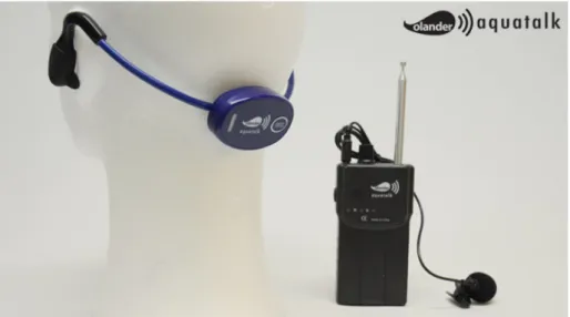
Being able to communicate with a swimmer in a swimming pool in a good way is not a new problem. Loud volume and noisy conditions in the swimming arena along with the fact that the swimmer is beneath the surface much of the time makes it hard. For a trainer to communicate with his or her student, several products exist on the market and one of them is the Olander Aquatalk [6].
CHAPTER 2. STATE OF THE ART 10
Figure 2.3: Olander Aquatalk
Olander Aquatalk is a form of walkie-talkie which utilizes bone conduction technology where the trainer can communicate with up to 10 swimmers at the same time. One problem with this product is however the prize tag of over e150 for just one headset. In this project there is no need for crisp and clear speech and the cost is an important factor. One way to transmit a signal from the tablet to the swimmer would be to use Bluetooth but since the frequency of its transmission is about 2.4 GHz and water highly absorb these frequencies, it wouldn’t be a good option. It also demands a handshaking between the device which is really not necessary. In addition to this, many of the cheaper tablets, including the one used in this project are not equipped with a Bluetooth chip.
Instead of Bluetooth, FM modules in the frequency spectra of 315-433 MHz are often used in remote controlled applications like this and have longer range so one of those modules should serve the purpose well.
3
|
Method
3.1
Requirements
The functional and non-functional requirements of the system are the following: 1. The system should be implemented on an Android tablet to enable display
of data for professional swimmers.
2. The tablet is to be mounted at the edge of a swimming pool meaning that the frontal camera of the tablet should be used.
3. OpenCV should be utilized as vision library.
4. The blind swimmer should be notified when she is near the pool edge. A device with a vibration motor should be attached to the swimmer. 5. No other applications should be allowed to run on the tablet, making it
fail safe from any user interactions.
3.2
Choice of platform
Making a console application in pure C++ code was first done. A couple of OpenCV programs were written and successfully cross-compiled for the target machine. Image transformations were done to files but there was and is no way to access the camera from within a console application. The OpenCV manual doesn’t explain this, it simply says that it’s not possible. Google doesn’t allow the camera to be activated and hidden in normal applications without the user being able to discover the execution of it so probably this console application restriction lies in the very nature of Android OS.
The second option was to install a different OS on the tablet but as already been covered in section 2.1.2 it’s not a suitable solution.
Instead of the former two choices, a traditional app was developed. Some of the benefits are the simplicity in installing it on practically any Android platform, good documentation and example programs. Also, calibration could easily be done and visualized by a Graphical User Interface (GUI).
The Android application was tested on a Teclast A11 tablet which is a low-cost tablet equipped with a 1.5 GHz ARMv7 rev 0 CPU, USB On-The-Go and a 0.3 megapixel frontal camera. The running operating system was Android 4.1 - Jelly Bean.
CHAPTER 3. METHOD 12
3.3
Software
This thesis focus on a well defined problem: the detection of a blind swimmer when she approaches the edge of a swimming pool using a tablet with its camera. In order to actually find a human body, e.g. the swimmer, several methods can be used.
The target swimmer uses the four classical strokes - butterfly stroke, back-stroke, breaststroke and front crawl - and was filmed during her exercise at two occasions with an iPhone 4 camera. At the first occasion, she wore a blue cap and was filmed with a handheld iPhone. Footage number two was made by an iPhone mounted on a tripod with an attached polarization filter while the swimmer wore a red cap. Given these two videos, an algorithm detecting the swimmer was to be developed. OpenCV was first installed on a MacBook Air and the programming language chosen was C++. When the algorithm had been proved working, the OpenCV code was imported into an Android project, embedded as native code.
3.3.1
Choice of method
As indicated in section 2, there are numerous ways to detect human motion and especially two of the methods proposed, [15] and [10] were considered. After the first footage was done, it was analyzed and different color thresholding techniques to extract just the blue cap from the surroundings were applied similar to the method of [10]. However, reflections in the water, the cap being almost the same color as the water and a shaky camera made it surprisingly difficult to isolate the swimmer cap from the surroundings.
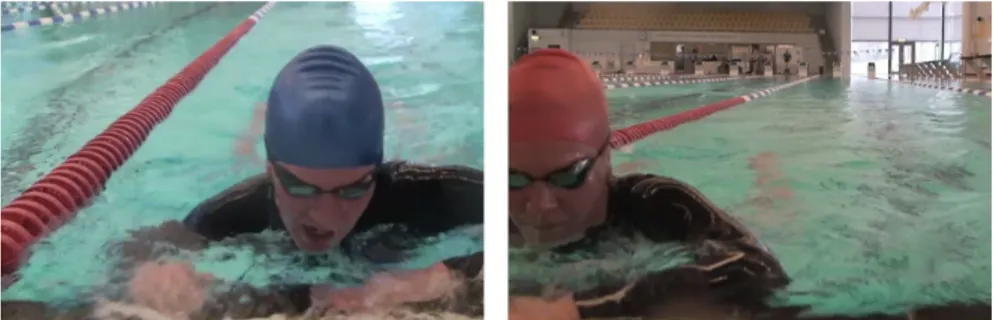
When filming her for the second time, a polarization filter was attached to the camera to remove some of the reflections from the water and a tripod for the camera was used so the conditions would be as close to the reality as possible. Instead of a blue cap, this time a red cap was used. See figure 3.1.
Figure 3.1: Comparison of the two videos. To the left, the swimmer wears a blue cap and to the right, a red cap.
3.3.2
Lucas-Kanade optical flow
One of the methods considered was inspired by [15]. Optical flow is an umbrella term for a technique which distinguishes the flow of motion in for example video streams. Lucas-Kanade is an optical flow algorithm that calculates the
CHAPTER 3. METHOD 13
displacement of pixels from frame to frame to see what direction the pixels are heading and depending on threshold values, they are classified as motion pixels. As seen in figure 3.2, motion is displayed as vector arrows where the length indicate the displacement of a pixel from the previous frame to the actual frame and the direction of the arrow indicate what direction it was heading. Due to the great amount of splashes and because the direction of the swimmer’s motion varies much from a frontal point of view, this method failed.
Figure 3.2: Lucas-Kanade optical flow applied on the video
3.3.3
Color thresholding with object estimation
The second method, which proved to be the best suited method was by searching for a specific color in a Region of Interest (ROI). In this case, a red cap was chosen since red color differs much from the water. The algorithm basically searches for red colored blobs and assumes the biggest one being the head of the swimmer. When there are no red blobs bigger than some threshold value and within the ROI, actions will be taken depending on if the algorithm has already found the swimmer in a previous frame or not. If the algorithm finds a valid object for the first time, a new estimation of the target will be created. This estimation object will be referred to as the estimate. If no red blobs are found but an estimate has been created earlier, meaning the swimmer has been detected previously, the estimate is updated in terms of position and size to match the swimmer’s head’s size and position now being underwater.
Swimline markings
The swimlines that separate the swimming lanes from each other follow certain standards in their markings. This application is particularly aimed for a pool which use the standard where the first 5 meters of the line, starting from the edge, are solid red. Having a distance reference in the image turned out to be of great help as will be shown.
CHAPTER 3. METHOD 14
Figure 3.3: Swimline color markings where the left edge is at the edge of the pool.
A problem that arose when changing the color on the swimcap from blue to red was that the swimlines and the cap now shared the same color.
Calibration
Before running the program, a calibration needs to be done. First of all, the color range needs to be set so that only red pixels are selected for further pro-cessing. There are several color spaces in which colors are represented where RGB probably is the most common one. However, for filtering out a specific tone, the HSV color space is more intuitive and appropriate. Cameras capture colors differently so the color range needs to be set for the specific camera to be used.
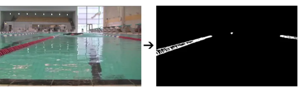
When the color space is set, the swimlines needs to be filtered out. To get rid of noise, gaussian blur is first applied to the image. Thereafter, the function
inRange is used to select the red hue.
//1. Convert to HSV color space
cvtColor(mRGB,mHSV,CV_BGR2HSV);
//2: Gaussian blur the image
for ( int i = 1; i < MAX_KERNEL_LENGTH; i = i + 2 ) GaussianBlur( mHSV, mHSV, Size( i, i ), 0, 0 );
//3: Inrange. Makes sure that only red tones are selected
inRange(mHSV, Scalar(hMin, sMin, vMin), Scalar(hMax, sMax, vMax), mHSV);
Figure 3.4: Before and after the conversion to HSV color space, gaussian blur and color thresholding
To fill in the ”holes” in the contours from the previous step, the dilate function is used.
CHAPTER 3. METHOD 15
//4: Dilation, filling in the holes
dilationType = MORPH_RECT; dilationSize = 3; Mat element = getStructuringElement( dilationType,
Size( 2*dilationSize + 1, 2*dilationSize+1 ), Point( dilationSize, dilationSize ) ); dilate( mHSV, mHSV, element );
Figure 3.5: Before and after the dilation morphology
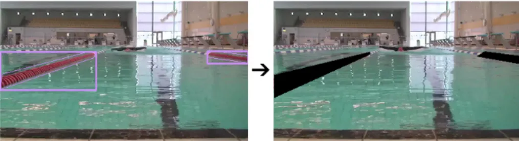
The red tones have now been binary thresholded meaning that the red toned pixels are displayed as white pixels and every other pixel is black. After the dila-tion step, every contour is searched for and the two biggest contours are filtered out by simply drawing black polygons a bit bigger than the actual swimlines and thus covering them. The final result of the filtering applied on the original image is seen in figure 3.6. In the calibration process, various user settings are saved in a data file. See the flowchart in figure 3.7 for the whole process. Every step until and including the finding of every contour will hereafter be referred to as the preprocessing of the image.
//5: Finds every red toned contour // ...
findContours( mHSV, contours, hierarchy, CV_RETR_TREE, CV_CHAIN_APPROX_SIMPLE, Point(0, 0) );
// End of preprocessing
// Filters out the two biggest contours, i.e. the swimlines // ...
fillPoly( mHSV, pptL, nptL, 1, Scalar( 0,0,0 ), lineType ); fillPoly( mHSV, pptR, nptR, 1, Scalar( 0,0,0 ), lineType );
CHAPTER 3. METHOD 16
Figure 3.6: Final result of the calibration, the two biggest red contours are located and filtered out.
Figure 3.7: Calibration flow chart
Estimation of target and hit classification
To ensure a 100% hit rate of the target even if she is underwater in the strike zone, an estimation of the target’s position and size is done whenever the algo-rithm lose track of the object. There are two scenarios in which the program chooses to ”hit” the swimmer. ”Hitting” refers to the assistant’s stick which is used to dab the swimmer’s head when she is near to the edge. If the target crosses a user set line in the image or if the target is bigger than a defined area, it is classified as a ”hit” meaning the program will send a signal to warn the swimmer.
The preprocessing function of the image frames returns all red contours and thereafter the biggest contour - if any contour at all was found - is selected for further processing. The program then goes through a series of checkpoints to see if the contour qualifies as the correct target. Some of the checkpoints are: check if the contour is within the ROI and above a set threshold in terms of size (so that noise won’t be classified as the target).
If the target is located for the first time, an estimate with the same proper-ties, inter alia position and size, as the target is initialized.
CHAPTER 3. METHOD 17
Figure 3.8: To the left: no target within the black square, i.e. the ROI is detected. To the right: the red cap is detected since a part of it is within the ROI. The width of the ROI is determined by the position of the two swimlines.
If in the next frame the target is not detected but an estimate exists, the estimate is updated in terms of position and size as in figure 3.9. The estimate of the target, not the target itself is what the program takes into account when about to warn the swimmer. By analyzing the speed of the swimmer and how the area of the head increases as she approaches the camera, the updating values of the estimate have been manually tuned so it matches the swimmer. See section 3.3.3 for an explanation of the variables to tune.
Figure 3.9: To the left: the target is located. To the right: the target is now out of sight but since it has been detected at least once, the estimate’s position and size is updated to match the swimmer now being underwater.
If the target is detected when an estimate already exist, the estimate is assigned the target’s position. The estimate is however only assigned the target’s area if the target’s area is bigger than the estimate’s area. Otherwise the area remains the same.
When an estimate has been created, the defined ROI is no longer of interest because the head can cover almost the whole screen when really near. Instead, a check is made to make sure that the change in position is not greater than some threshold value from frame to frame. If the estimate’s position passes the position threshold line, of if the area is greater than the area threshold, it is considered as a hit as indicated by the green circle in figure 3.10
The flow chart of the native function which returns the current state of the program is seen in figure 3.11.
CHAPTER 3. METHOD 18
Figure 3.10: To the left: the target is detected but is not close or big enough. To the right: the red target crosses the ”position hit threshold” line. See section 3.3.3 for an explanation of why the line has a slope.
Figure 3.11: Native function in detail
Variables and settings
A number of variables need to be tuned for the program to function correctly. All of them can be set from within the Android application.
Color range The HSV color range needs to be defined in order to extract only the red cap.
Area threshold values There are two area thresholds that needs to be set:
areaNear and areaHit. The areaNear variable determines the lower threshold
the contour area must exceed in order to be considered the true target. The areaHit variable is the upper threshold. A contour exceeding the areaHit value, is classified as a hit.
Position threshold values Just like the area, there are two variables repre-senting the position thresholds: yNear and yHit. yNear determines the upper line of the ROI square which the swimmer must pass to be of interest. If the
CHAPTER 3. METHOD 19
swimmer crosses the yHit line a warning should occur. A third variable, ySlope, representing the slope of the yHit line is also subject to user intervention. A sloped line is motivated by the fact that the swimmer tends to follow the left swimline. According to simple geometry, the distance from the camera to the swimmer is greater when she is near the swimline compared to directly in front of the camera. This is of big importance when the swimmer uses backstroke. A first order function, y = kx + m is adequate.
The estimate’s update values When an estimate has been initiated and the swimmer is out of sight, the position and size should be updated. In the video material given, the swimmer reaches the wall, i.e. finishes 14 times. The
estimateUpdateY and estimateUpdateArea have been tuned to match the speed
and size of the swimmer’s head as good as possible in the 14 examples. The estimate’s position and area are updated like:
estimate.y = estimate.y*estimateUpdateY; estimate.area = estimate.area*estimateUpdateArea;
which implies that the updating is greatly affected by the frame rate of the video stream. A higher frame yields additional updates compared to a lower frame rate. The target platform runs at around 10-12 fps so a frame loss was added to the material to match the final product.
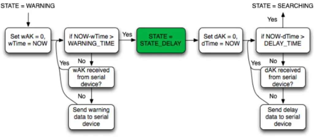
Delay times When the swimmer is to be warned, the program enters the state
STATE_WARNING and executes the warning signal. Thereafter, the program
changes state to STATE_DELAY. The STATE_DELAY is introduced so the swimmer has enough time to exit from the ROI without being detected when swimming away from the camera. The time length of these two states can be adjusted.
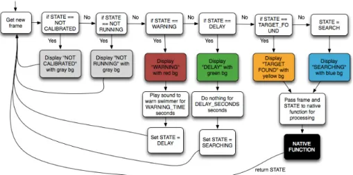
The complete algorithm
The complete algorithm with its 6 different states, STATE_NOTCALIBRATED, STATE_NOTRUNNING, STATE_SEARCHING, STATE_TARGETFOUND, STATE_WARNING and STATE_DELAY, implemented on the Android tablet is seen in figure 3.12.
CHAPTER 3. METHOD 20
Figure 3.12: Main program state machine: thread that fetches new frames from the camera
3.3.4
Fail safe
Allowing just one application to run is done by locking the tablet into kiosk mode. An easy solution for this is by installing a kiosk lockdown application such as SureLock. It prevents all other applications except the ones selected to run and disables user interactions while in those applications.
3.4
Hardware
To send a signal only detectable by the swimmer, two systems have been devel-oped. One of them is intended for tablets equipped with USB On-The-Go and the other one for tablets not equipped with USB On-The-Go. Both of them consist of basically an FM transmitter module and an FM receiver module with an attached vibration motor to it. What differs the systems is what triggers the activation of the transmitter. In the system intended for non-OTG devices, the transmitter is triggered by a soundwave (slow) through the audio jack of the tablet and in the other, it is triggered by a serial signal (fast). The tablet should serve as an on and off switch for the vibration motor when the swimmer is in range.
3.4.1
Soundwave triggered system (non-OTG devices)
LM567
The LM567 circuit is a tone decoder which saturates a transistor making current flow through a load if the frequency of the input signal is within a certain bandwidth. The bandwidth is set by the choice of resistors and capacitors on the other pins. The center frequency can be set in the range of 0.01 Hz and 500 kHz and it can drive a 100 mA load.
CHAPTER 3. METHOD 21
Figure 3.13: AC Test Circuit from the LM567 datasheet
To determine the center frequency and bandwidth, the formulas
fo∼= 1 1.1∗ R1∗ C1 (3.1) BW = 1070√( Vi fo∗ C2 ) in % of fo (3.2)
are used where Vi = Input voltage (volts rms), Vi ≤ 200mV and C2 =
Capaci-tance at Pin 2(µF)
A 10K resistor was chosen as R1 and a 15nF capacitor as C1. giving a
theoretical center frequency of 6 kHz. However, using a frequency generator showed that the transistor was saturated within the interval 6.6 kHz to 7.4 kHz. A 6.9 kHz sinewave was therefore recorded and used as the input signal to the system.
3.4.2
Serially triggered system (OTG devices)
Android devices running Android 3.1 or higher utilize a USB host API. It means that the device, when in USB host mode, powers the bus and enumerates con-nected hardware.
USB serial library for Android
A serial library for Android with drivers implemented in Java was written and last updated in 2012 by Mike Wakerly [9]. It is compatible with many se-rial chips, e.g. FT232R. To manage the sese-rial commands and to activate the transmitter, an Arduino Nano microcontroller board which is equipped with a FT232R chip was used.
CHAPTER 3. METHOD 22
Figure 3.14: Arduino Nano V3.0, image from robot gear.com.au.
See figure 3.15 for an overview of the serial communication seen from the tablet’s point of view.
Figure 3.15: Serial communication seen from the tablet’s point of view. What happens is that whenever the algorithm enters STATE_WARNING, an acknowledgement variable wAK is reset and the actual timestamp is saved. Thereafter, the program enters a loop where it sends data for activating the transmitter to the serial device and waits for a confirmation from the device for
WARNING_TIME seconds defined by the user. It will re-send the activation
data until it has received an acknowledgement which will set the wAK variable to 1. The same procedure happens in the next state, STATE_DELAY, but the data sent is instead for turning off the transmitter.
The microcontroller simply waits for serial data to arrive and as soon as activation data is received, a digital pin is toggled HIGH and an
acknowledge-CHAPTER 3. METHOD 23
ment byte is sent. When deactivation data is received, the digital pin is toggled LOW, also followed by an acknowledgement byte.
3.4.3
PT2264/PT2294 encoder/decoder
Figure 3.16: PT2264/PT2294 encoder/decoder, image from t.akingsky.cn The PT2264 circuit is an encoder which is paired with the PT2294 circuit utilizing CMOS technology. It has over 500 000 user-selectable address codes and operates with a frequency of 315 MHz. This pair controls the toggling of a small 5V relay. Building this, the transmitter circuit with the antenna was removed from its casing and connected to the output from the tone decoder (soundwave triggered system) or the output from the microcontroller (serially triggered system). The power button was bypassed so whenever a 6.9 kHz sinewave is sent to the LM567 circuit or activation data is sent to the microcon-troller, the transmitter is activated and the relay is toggled. When the signal is active, the relay lets current flow through a vibration motor and whenever the sinewave is stopped/deactivation data is sent, the relay cuts the current to the motor.
As mentioned earlier, the LM567 can drive a load of 100 mA which is more than enough for the transmitter. The current flowing through the transmitter when active was measured to be around 20 mA. In the serially triggered system, the output form a digital pin was used to saturate a transistor, thus activating the transmitter. The maximum DC current of every Arduino Nano I/O pin is 40 mA but since the transmitter needs 12V, it couldn’t be directly connected to the output.
Two of these transmitters with the same address code were used since tablets should be detecting the swimmer on both sides of the swimming pool.
3.4.4
Vibration motor
A 12*3.4mm cell phone vibration motor has been used. It consumes about 80 mA and operates in the voltage range of 1.5V-6V. Two diodes have been used to lower the voltage from 5V to around 3.8V.
CHAPTER 3. METHOD 24
Figure 3.17: Vibration motor
3.4.5
Summary of the complete circuits
The PT2264 circuit requires 12V. Therefore, a 12V adapter with a switched regulator was used to drive the tone decoder at 5V in the soundwave triggered system. A capacitor across the transmitter circuit was needed to keep a con-stant transmission without voltage drops. In the serially triggered system, the transmitter was placed between the transistor collector and the 12V supply.
The FM receiver unit was designed for utilizing a 12V 23A battery due to its small size. A switched regulator bringing down the voltage to 5V was needed for the circuitry and the motor. See figure 3.18, 3.20 and 3.19 for the complete drawings of the circuits.
CHAPTER 3. METHOD 25
Figure 3.19: FM transmitter circuit - serially triggered system.
4
|
Experiments and results
4.1
Wireless transmission time lag and
robust-ness
To measure the time it takes from the state where the tablet sends out its warning signal to the state where the signal has reached the target, a camera with 30 fps was used and the distance between the transmitter and the receiver was about 4 meters. With both the soundwave triggered system and the serially triggered system, 10 warning signals were generated with about 60 seconds in between which should be a legitimate scenario. The time it took to activate the transmitter and to toggle the receiver relay, thus turning on the motor, was measured.
4.1.1
Soundwave triggered system time lag
n Frames / time to turn Frames / time to Frames / time to on the transmitter turn on the motor turn off the motor 1 9 / 0.3s 14 / 0.467s 9 / 0.3s 2 8 / 0.267s 12 / 0.4s 8 / 0.267s 3 9 / 0.3s 14 / 0.467s 9 / 0.3s 4 12 / 0.4s 17 / 0.567s 7 / 0.23s 5 9 / 0.3s 14 / 0.467s 6 / 0.2s 6 11 / 0.367s 15 / 0.5s 7 / 0.23s 7 10 / 0.33s 15 / 0.5s 8 / 0.267s 8 9 / 0.3s 14 / 0.467s 8 / 0.267s 9 8 / 0.267s 14 / 0.467s 7 / 0.23s 10 9 / 0.3s 14 / 0.467s 6 / 0.2s
Table 4.1: Soundwave triggered system time lag when signal is sent every 60 seconds.
The Worst-case Execution Time (WCET) to turn on the motor was 0.567 seconds and the average time was 0.477 seconds. To turn off the motor, the WCET was 0.3 seconds and the average time was 0.25 seconds.
Based on these measurements, a time lag of about 0.6 seconds should be taken into consideration when calibrating the algorithm for the soundwave trig-gered system.
CHAPTER 4. EXPERIMENTS AND RESULTS 27
4.1.2
Serially triggered system time lag
n Frames / time to turn Frames / time to Frames / time to on the transmitter turn on the motor turn off the motor 1 2 / 0.067s 7 / 0.233s 4 / 0.133s 2 1 / 0.033s 6 / 0.2s 5 / 0.167s 3 1 / 0.033s 6 / 0.2s 4 / 0.133s 4 2 / 0.067s 7 / 0.233s 5 / 0.167s 5 2 / 0.067s 7 / 0.233s 6 / 0.2s 6 2 / 0.067s 6 / 0.2s 5 / 0.167s 7 1 / 0.033s 6 / 0.2s 4 / 0.133s 8 0 / <0.033s 6 / 0.2s 6 / 0.2s 9 2 / 0.067s 7 / 0.233s 5 / 0.167s 10 1 / 0.033s 7 / 0.233s 5 / 0.167s
Table 4.2: Serially triggered system time lag when signal is sent every 60 seconds. The WCET to turn on the motor was 0.233 seconds and the average time was 0.216 seconds. To turn off the motor, the WCET was 0.167 seconds and the average time was 0.163 seconds.
Based on these measurements, the time lag is almost negligible in the serially triggered system. The time it takes to activate the transmitter is heavily reduced from up to 0.4 seconds (soundwave triggered system) to about 0.067 seconds. The time between the activation of the transmitter and the receiving of the signal is of course the same for both systems. However, turning off the motor is also faster in the serially triggered system. The reason why is because it doesn’t need a capacitor across the transmitter which was needed in the soundwave triggered system.
4.1.3
Robustness to turbulence
Since the swimmer is not in a fixed position, the signaling system must be robust and handle movement well. To somehow measure the robustness, the transmitter was fixated and the receiver was exposed to turbulence similar to what it will be exposed to while mounted on the swimmer. The receiver was held in the hand of a human while she flapped her arm trying to mimic the different swimming techniques behavior. She started close to the transmitter and moved farther away slowly to see when the signal would start to get unstable. This was done in an open setting with no obstacles between the transmitter and the receiver. It turned out that at about 12 meters, the signal would cease to be completely reliable.
CHAPTER 4. EXPERIMENTS AND RESULTS 28
Figure 4.1: The transmission is reliable within 12 meters range. A range of 12 meters and higher gives unreliable behavior.
4.2
Comparison between the proposed algorithm
and the reference stick with 10, 12 and’ 15
fps
The footage the proposed algorithm was applied on was filmed with an iPhone 4 with a framerate of 25 fps. The tablet the program was targeted for can only record at a speed of around 12.5 fps as maximum. With this in mind, frame losses were simulated so the footage would match the target equipment in terms of speed of the camera and platform. With the same algorithm settings, a frame loss of 10, 13 and 15 fps was simulated yielding a program speed of 15, 12 and 10 fps. Also, the video frames were reduced in size before manipulated to a height of 240 pixels to match the dimension of the tablet frame size of 320x240 pixels.
In the video, the blind swimmer practice all four swimming strokes: the butterfly stroke, backstroke, breaststroke and the front crawl. The swimmer approaches the edge of the pool a total of 14 times. When applying butterfly stroke and backstroke, she finishes 3 times each and when applying breaststroke and front crawl, she finishes 4 times each.
When conducting these experiments, the algorithm was tuned for a time lag of 0.5s because that’s what the first measurements of the transmission speed indicated.
In figure 4.2, 4.3 and 4.4, comparisons between the proposed algorithm and the reference stick can be seen. The purple, blue and the green colored bars indicate how many frames before the wall the algorithm, the algorithm + time lag and the reference stick ”hits” the target swimmer. There is also a red colored bar which is a personal estimation of a critical zone and a thin black bar which indicate the wall. The swimmer should, according to the video, be notified before entering the critical zone to be sure not to hit the wall.
CHAPTER 4. EXPERIMENTS AND RESULTS 29
Figure 4.2: Comparison between the proposed algorithm and the reference stick with 10 fps (15 frames discarded)
CHAPTER 4. EXPERIMENTS AND RESULTS 30
Figure 4.3: Comparison between the proposed algorithm and the reference stick with 12 fps (13 frames discarded)
CHAPTER 4. EXPERIMENTS AND RESULTS 31
Figure 4.4: Comparison between the proposed algorithm and the reference stick with 15 fps (10 frames discarded)
CHAPTER 4. EXPERIMENTS AND RESULTS 32
In the following table, the average time before the swimmer reaches the wall is listed for the algorithm with time lag and the reference stick. Also, the mean deviation and the mean deviation divided by the average value are presented.
FPS Alg Stick Alg mean Stick mean Alg mean Stick mean avg avg deviation deviation deviation deviation time time divided by divided by
(s) (s) avg time avg time
10 1.06 0.74 0.21 0.24 0.19 0.33 12 1.11 0.73 0.23 0.22 0.21 0.3 15 1.16 0.7 0.25 0.22 0.21 0.31
Table 4.3: Values representing all four swimming strokes in the comparison between the proposed algorithm and the reference stick
Table 4.2 tells that the assistant notifies the swimmer around 0.73 seconds before she reaches the wall in average whereby the algorithm average time is about 1.11 seconds. In a percental aspect, the difference between these two values is quite large but the algorithm is more smooth in terms of mean deviation divided by the average time. In addition to this, it never notifies the swimmer within the critical zone which in the end is what matters most.
When no image manipulations are done, the Teclast A11 tablet captures frames and displays them at about 10-12.6 fps. Some minor adjustments to the algorithm had to be done when porting the code to Android because the frame rate was at first reduced to around 6-8 fps. Reducing the amount of gaussian blur a bit speeded up the algorithm without compromising the per-formance so eventually, no difference in speed could be noticeable between the non-manipulating program and the program running the proposed algorithm. The conclusion drawn from this is that it’s the capturing of frames which is the bottleneck in terms of speed.
Comparisons were made with a frame rate of 10, 12 and 15 and the algorithm detects and warns the swimmer meritorious when she is about 1.11 seconds before the wall in average.
In all strokes but the front crawl, the swimmer grasps the edge before turn-ing. When using the front crawl stroke however, the swimmer makes a forward somersault directly after she is hit, not touching the wall with her hands. There-fore, the striking of the assistant is set as the starting point for the critical zone, assuming the assistant strikes at the optimal moment.
5
|
Conclusions and discussion
When developing this application, many obstacles had to be overcome. Follow-ing is a list of the most severe problems faced durFollow-ing this thesis wrapped up by a summary.
5.1
FM transmission
The first thought was to use an FM transmitter operating in the FM band of 88-108 MHz and equip the swimmer with a waterproof FM radio with earphones. A requirement added some time into to the project was however that a vibration should warn the swimmer and not sound from earphones. The signal from the receiver could then be connected to the LM567 tone decoder and if a sinewave of a certain frequency would have been detected, it would somehow drive a motor. This solution failed however because of the receiver picking up too much noise. The next idea was to use the PT2262/PT2272 transmitter/receiver pair which is a similar pair to the PT2264/PT2294 chosen. These modules proved to be really unstable and sensitive for electromagnetic interference. A lot of time was spent on getting a stable transmission of the signal but the presence of a human being could heavily disrupt it.
Figure 5.1: PT2262/PT2272 encoder/decoder, image from t.akingsky.cn At last, the PT2264/PT2294 pair was tried out and passed the tests.
CHAPTER 5. CONCLUSIONS AND DISCUSSION 34
5.2
Placement of the camera
The placement of the camera is in fact quite horrible. When the swimmer approaches the camera, severe splashing is taking place which often covers the swimmer completely which complicates the detection. In addition to this, the swimmer’s movement is following a zig-zag movement in two of the techniques: the butterfly stroke and the breaststroke. Those techniques force the swimmer to move in a twitchy manner not optimal for motion tracking.
Figure 5.2: Swimmer following a zig-zag movement.
Because of the placement and since only just one camera was used, the yHit line needs to be really fine tuned. A deviation of a few pixels from the ultimate line can in fact mean a difference of a great distance in reality. If the camera instead would have been placed over the swimming pool, higher precision would have been obtained.
5.3
Performance measuring
When a new algorithm is proposed, it is often benchmarked to see how well it solves various problems compared to other existing algorithms to get an idea of how good it is. In this case, precise benchmarking can’t really be done. The only reference available is the assistant’s stick which is not flawless. Therefore, the benchmarking might not be 100% exact but the comparisons give a hint of what is possible to achieve with this solution.
What’s worth to point out from the comparisons in section 4.2 is that the reference stick sometimes is too late in its notification when the swimmer prac-tices butterfly stroke and breaststroke. The reason why is because the swimmer is underwater periodically so if she makes a dive when the stick is just out of reach, she ends up really close to the wall by the time she can be hit by the stick again. The two other strokes, backstroke and front crawl, are more predictable in that way.
CHAPTER 5. CONCLUSIONS AND DISCUSSION 35
Figure 5.3: Assistant striking the head of the swimmer when she is very close to the wall - butterfly stroke and breaststroke
Figure 5.4: Assistant striking the head of the swimmer at a safe distance from the wall - backstroke and front crawl
Making an accurate measurement of the performance of the algorithm wasn’t really necessary because the tablet could only capture frames at about 10-12.6 fps and no difference could be seen between a purely dedicated video streaming application and the application running the algorithm developed. A secondary goal when developing the application was to keep down the cost of the system as much as possible. Therefore, the algorithm was designed for low-cost tablets. However, the performance of the algorithm would increase if adapted for a tablet with a higher frame rate. When approaching the camera, the swimmer was sometimes only above the water surface for 12 frames in the 25 fps videos. This implicates that she would only be detectable for 6 frames when using a 12 fps camera. A higher frame rate camera would therefore make the detection more smooth and the risk of missing the swimmer would be less.
5.4
Summary
The concept of replacing the striking of a human hand with a tablet and a camera has been proved working and has been proved to be even more reliable when calibrated well. While the assistant sometimes can’t notify the swimmer when she is underwater, forcing a strike in the critical zone near the edge, this system is indeed able to.
Another implementation in mind when developing this system was to display data like lap times for non blind swimmers. The choice of searching for a specific color instead of motion is more appropriate and is easily extended in that respect as swimmers can be uniquely identified by wearing different colored
CHAPTER 5. CONCLUSIONS AND DISCUSSION 36
caps. Instead of just searching for the color red, the system could identify multiple swimmers and record their progress.
The choice of operating system on the tablet started off being one of the key matters to address. However, as investigation proceeded, it quite early seemed too complex and not enough motivating to set up another Linux distribution and build an app for that OS instead of building for Android. Therefore, the decision to use Google’s tools for developers instead of making a deep dive into Linux core programming was taken early, closing that topic.
6
|
Future work
Although the system is indeed working as intended, several improvements can be done summarized below.
Control system for updating the estimate
Currently the position and size of the estimate are updated by multiplying the current value with a constant. This approach means the frame rate is of great impact to the system. To make the application even more user friendly and autonomous, the update variables could be set automatically and tuned in real time by a control system.
Stereo vision
To make the approximation of the distance to the swimmer more accurate, stereo vision could be implemented utilizing the USB On-The-Go and an external webcam.
Non blind swimmer application
This thesis serves as a base for future extension of the application to recognize multiple swimmers and display their lap times and various data.
Battery level monitor
If more time had been available, a battery level monitor would have been added to the FM receiver circuit to ensure that the swimmer would stop and replace the battery when almost drained instead of maybe hitting the pool wall believ-ing the warnbeliev-ing system was still online. The device could warn the swimmer by activating a buzzer when the battery voltage level had reached a certain threshold.
PCB
The components used for the FM transmitter and receiver are of through-hole type. Especially the receiver module could be drastically minimized by making a PCB with surface mounted components.
Bibliography
[1] Ada on android. http://rveenker.home.xs4all.nl/Ada%20on% 20Android.html. [Online; accessed 2-April-2013].
[2] Android ndk as standalone toolchain. http://www.kandroid.org/ndk/ docs/STANDALONE-TOOLCHAIN.html. [Online; accessed 2-April-2013]. [3] Announcement of android ndk. http://android-developers.blogspot.
se/2009/06/introducing-android-15-ndk-release-1.html. [Online; accessed 2-April-2013].
[4] Gnat ada compiler. http://www.dragonlace.net/posts/GNAT_AUX_ ported_to_Android/. [Online; accessed 2-April-2013].
[5] Number of apps in google play. http://readwrite.com/2013/01/08/ google-play-to-hit-1-million-apps-before-apple-app-store. [On-line; accessed 6-May-2013].
[6] Olander aquatalk. http://www.olanderswim.se/olander-aquatalk/. [Online; accessed 6-May-2013].
[7] Opencv4android. http://opencv.org/platforms/android.html. [On-line; accessed 6-May-2013].
[8] Ubuntu tablet. http://www.ubuntu.com/tablet. [Online; accessed 6-May-2013].
[9] Usb serial library for android - written by mike wakerly. http://code. google.com/p/usb-serial-for-android/. [Online; accessed 17-May-2013].
[10] Youtube video made by the user proeng89. the user has used functions such as color detection, thresholding and blob detection with opencv as library. http://www.youtube.com/watch?v=ylWAT1gxaQ8/. [Online; accessed 6-May-2013].
[11] Che Yon Choo, Hui Qing See, Z. J. T., and Lee, Y. Human detection
using Histogram of oriented gradients and Human body ratio estimation, Computer Science and Information Technology (ICCSIT), 2010 3rd IEEE International Conference on (Volume:4 ) (2010).
BIBLIOGRAPHY 39
[12] Cheng-Min Lin, Jyh-Horng Lin, C.-R. D., and Wen, C.-M.
Bench-mark Dalvik and Native Code for Android System, Innovations in Bio-inspired Computing and Applications (IBICA), 2011 Second International Conference (2011).
[13] Lars Cederholm, N. P. Stereo Vision System for an Autonomous Robotic Platform, Master thesis (2011).
[14] P.-M. Jodoin, V. S., and Konrad, J. Modeling background activity
for behavior subtraction, IEEE ICDSC 2008, Stanford, California, USA
(2008).
[15] Tian, Y.-L., and Hampapur, A. Robust Salient Motion Detection with Complex Background for Real-Time Video Surveillance, Application of Computer Vision, 2005. WACV/MOTIONS ’05 Volume 1. Seventh IEEE Workshops on (Volume:2 ) (2005).
A
|
Terms and OpenCV
in-stallation on Mac OS
A.1
Technical terms and terminology
Glossary
GCC GNU Compiler Collection. 7
Histogram of Oriented Gradients Feature descriptors used to detect ob-jects. 9
HSV Hue, saturation and value color space. More intuitive way of representing a color than the RGB model. 14
IDE Integrated Development Environment. 8 JNI Java Native Interface. 7
Kiosk mode Basically, kiosk mode is the Android mode in which only one application is permitted to run. The device is locked to the specific kiosk application.. 20
NDK Native Development Kit - A toolset used when implementing native code like C or C++ in your app, http://developer.android.com/tools/ sdk/ndk/index.html. 8
Optical Flow Motion pattern in image frames. Popular methods for calculat-ing optical flow are: Lucas-Kanade and Horn-Schunck. 9
Preprocessing In this context, the preprocessing consist of 5 steps. Con-version of color space from RGB to HSV –> Gaussian blur –> Color thresholding –> Dilation –> Finding of every contour. 15
RGB Color space model where every color is represented by red, green and blue values between 0 and 255. 14
ROI Region of Interest. 13, 16–19
Glossary 41
SureLock Application that locks the tablet in kiosk mode making it safe from user interactions.. 20
Temporal Differencing Perhaps the simples method to extract movement. In two or more consecutive frames, the difference between them is classified as motion. 9
USB On-The-Go USB On-The-Go enables devices to be attached to the tablet and serial data to be exchanged between the units... 4, 11, 20, 37
WCET Worst-Case Execution Time. 26, 27
A.2
Rooting the tablet
Rooting is a process which makes the user gain full access, root access to An-droid’s subsystem. It is similar to jailbreaking iOS devices. It will for example allow the user to flash custom ROMs, install apps to the SD card, deny app permissions, overclock the CPU and configure restricted settings.
Some Android devices are harder to root than others but many of them can be rooted by a standard procedure with a program called SuperOneClick which is only available for Windows. I struggled trying to root the tablet. Following is an excerpt of the log I wrote when trying to root the tablet.
”A user following the guide at this site did manage to root his or her Teclast A11 tablet but I’ve tried that with a virtual machine of Windows 7 and it just doesn’t find my device within the rooting process. I can find it using just ”adb devices” but the rooting process always fails.
I’ve also tried using the BreakDroid app for Mac OS. First I tried ”Root multiple device” but it refused to find the device there as well. Using their ADB troubleshooting app, it could find the device using adb test 1 but not using adb test 2. I later tried the GingerBreak which finished and said it had successfully rooted the device. However, the tablet did not start first so I thought it might have been bricked since the GingerBreak should be used for Gingerbread Androids and not Jelly Bean. Luckily, it did start eventually and now I’ll try a third approach following the guide at this site.
The program ZhuoDaShi finds one device but can’t tell which one it is. I tried to set is a Teclast A10 but it refused to accept that. Going for a fourth approach.”
I finally succeeded by following the procedure found in:
http://forum.xda-developers.com/showthread.php?t=2033106 and http://blog.sina.com.cn/s/blog_899fd55d01017nsb.html.
Glossary 42
A.3
Getting started with Android on Mac OS X
10.8.2 Mountain Lion
First I followed these guidelines which means that I downloaded the Android SDK which included Eclipse + ADT plugin, Android SDK tools, Android Platform-tools, the latest Android platform and the latest Android system im-age for the emulator. To see if the connection with the Android device was working, I started a terminal session and ran
$ adb device
The Android device was however not found in the list so I had to go to the System Profiler and check the vendor id of the attached USB device. The id was in this case 0x2207. I then created a file callede/.android/adb_usb.ini and simply added the line 0x2207 to the file. After that, I restarted the adb server [a].
$ adb kill−server
$ adb start−server
And it was now showing the device and on the display on the tablet I could also see that USB debugging mode was enabled.
Shortly after that, I could build my first Android app by following the guide at this site. Later I followed the guide at this site to view the OpenCV examples on the tablet. Works like a charm but I had to download the Android NDK and add its directory path to the .bash_profile file as in this site.
exportPATH=/usr/local/bin:/usr/local/sbin:/ Users/z/Documents/exjobb/android−ndk−r8b:$PATH
exportNDKROOT=/Users/z/Documents/exjobb/android−ndk−r8b
A.4
OpenCV on Mac
To get started with the actual programming of OpenCV I figured it was easier to write C or C++ programs without the interference with Java so I decided to install OpenCV on my Mac computer following this guide.
A.5
Compiling and cross-compiling for ARM
Executing native programs on the tablet can be done in two different ways: using a compiler on the target platform to build the program or by using a cross-compiler on the source machine. I first tried compiling programs on the target machine and later, cross-compiled as seen in the following sections.
Glossary 43
A.5.1
Compiling on the target machine
I installed the app C4Droid from Google Play with its GCC-plugin. I actually had to download them from someplace else because I couldn’t access them from China. Anyhow, the C4Droid is an app which will let you write your own C-code and then compile it and run it in that program or from a terminal emulator. The procedure was just to install it and then I could run code. Accessing the tablet using adb shell I could also use arm-linux-androideabi-gcc file to compile programs I could just make use of the GCC and not use the C4Droid app itself which is a lot more convenient.
I followed the guide at this site.
A.5.2
Cross-compiling for the target machine
Following the guide at this site I started by downloading the latest Android NDK package, r8d, and extracted the files in a custom folder (/tmp/my-toolchain/). After that, I added the following lines to my .bash_profile file:
exportPATH=/tmp/my−toolchain/bin:$PATH
exportCC=/tmp/my−toolchain/bin/arm−linux−androideabi−gcc
exportNDK=/Users/z/Documents/exjobb/android−ndk−r8d/
exportSYSROOT=$NDK/platforms/android−9/arch−arm
The android-9 part means that it will compile for systems compatible from API level 9 and higher and the last part, arm-arch means that the target archi-tecture is ARM. The custom toolchain was built by using the make-standalone-toolchain bash file as in:
$NDK/build/tools/make−standalone−toolchain.sh −−platform=android−9 −−install−dir=/tmp/my−toolchain
I ran the previous command in a shell to install the specific toolchain for my platform.
B
|
Android application
B.1
Running mode
When the user starts the application for the first time, she is greeted by a purple screen indicating that a calibration needs to be done. If a serial device is not connected to the tablet, the text ”(NO SERIAL DEVICE CONNECTED)” will be shown beneath the NOT CALIBRATED text. The program will then only enable a soundwave for triggering the transmitter.
Figure B.1: Screenshot of STATE_NOTCALIBRATED
When the user clicks on the screen, a menu appears as shown in figure B.2. When the calibration has been made, the program can be in one of the follow-ing states: NOTRUNNING, SEARCHING, TARGETFOUND, WARNING or DELAYING as shown in figures B.3, B.4, B.5, B.6 and B.7.
APPENDIX B. ANDROID APPLICATION 45
Figure B.2: Settings menu displayed. To the left, the real time video stream is shown with the settings applied. By clicking on ”Settings”, the view is changed to the settings.
APPENDIX B. ANDROID APPLICATION 46
Figure B.4: State: SEARCHING
APPENDIX B. ANDROID APPLICATION 47
Figure B.6: State: WARNING
APPENDIX B. ANDROID APPLICATION 48
B.2
Settings mode
Here, all the variables defined in section 3.3.3 can be changed. The big picture to the left in figure B.8 displays the current settings applied. The areaNear and areaHit thresholds are seen in the top left position of that picture, the ROI is displayed as a square with no bottom line, the yHit line is shown and also the filtered out swimlines. Note that for the swimlines to be correctly filtered out, a calibration has to be made.
Figure B.8: Settings view
B.2.1
Color thresholding calibration procedure
The middle image displays the live video with the color thresholding applied. By changing the HSV seekbars, the image changes. The white parts of the image are what passes the thresholding so the red cap and the red swimlines should be white in the image when calibrating. Lastly, the image to the right displays the two biggest contours found after the color thresholding have been applied surrounded by rectangles. When calibrating, the two swimlines should be marked by two rectangles.
When the color thresholding seems fine and the two swimlines are marked, click the rightmost button to calibrate. When a calibration has been made or whenever settings have been changed, they need to be saved which is done by clicking the save button. See section B.2.3.
B.2.2
Updating of estimate values and other variables
The rest of the seekbars are used for tuning the estimate’s updating value and for setting the area thresholds. By changing the AREA seekbars, the two circles in the leftmost image are changed accordingly. By changing the POS seekbars, the ROI and the yHit line are changed. These changes are also seen in the leftmost image.
APPENDIX B. ANDROID APPLICATION 49
After any changes have been made, they have to be saved which is done clicking the save button. See section B.2.3.
B.2.3
Settings buttons explained
Figure B.9: Settings buttons explained
The warning sound button only matters for the soundwave triggered system. In the serially triggered system, data is always sent if there is a serial device connected to the tablet.