GENERATE LIGHT WITH WIND POWER
FOWAD IQBALMASTERTHESIS 2012
Master in Product Development with a specialization INDUSTRIAL DESIGN
GENERATE LIGHT WITH WIND POWER
FOWAD IQBALThis degree project is performed at the School of Engineering in Jönköping in the subject field Industrial design. The project is a result of the master program Industrial design. The writers are responsible of the result, conclusions and reflections.
Tutor: Lars Eriksson Extent: 30 points (D-level) Date:
Abstract
The report explain the steps taken to improve a product (SOLVINDEN), which uses sun and wind energy to generate light and is used for outdoor decoration. The research involves improvements in both design as well function. As the form follows function in the product functionality of the form is very important in selection of the form. Some of important topics which are considered are different way of using wind to charge batteries, blades profiles and shape, way of optimizing generator, ratio of the optimal solution between of how much wind power is needed to start charging and charging efficiency. The report also includes different way of manufacturing, testing and finalizing the right form after optimizing. The solar power and the batteries are not in the scope of the project.
Summary
As the product SOLVINDEN harvest both wind and sun energy to generate current it is found that wind part of the product is not generating enough energy as compare to the solar part. In order to solve this problem different steps are taken in form of design process .Numerous objectives are provided by IKEA in the start of the project however before starting, the product is tested and different graphs are generated to find the problem in the product which are later added to the objectives.
Besides looking fun and attractive the products also have to function efficiently. Lot of research is done on the aerodynamics, wind turbines and generator. Mood board, idea tree, group brainstorming, functional analysis, concept sketches and CAD visualizing is done before evaluating different forms. After choosing few forms the detail CAD models are completed and they are send to IKEA pattern shop for manufacturing. Proper dimension and specific methods are chosen to manufacture different forms. NACA profiles (24) are also used in the designing of blade. Two main kinds of forms which are used in the process are one which uses drag and other which uses both drag and lift force to work. The forms are tested and optimized in later stages. Different kind of generators and their properties are also studied to understand the efficient ways to generate maximum energy at low RPM. The forms are also tested with different generators to find right combination of form with right generator.
Acknowledgements
I would like to thanks Malin Carlberg and Philip Holm from IKEA of Sweden , Lars Eriksson , Magnus Andersson and Olle Claesson from Jönköping university and windforce.se for their support and guidance.
Table of contents
Abstract ... 1 Summary ... 2 Acknowledgements ... 3 Table of contents ... 4 2 Introduction ... 6 2.1 BACKGROUND ... 8 2.2 OBJECTIVES... 9 2.3 FACTORS ... 10 2.4 DELIMITATIONS ... 10 3 Theoretical Background ... 11 3.1 DESIGN THINKING ... 11 3.1.1 Problem formulation ... 11 3.1.2 Solution Generation ... 11 3.1.3 Process strategy ... 12 3.2 THEORIES OF THINKING ... 12 3.3 DESIGN MEANING... 13 3.4 AESTHETICS ... 14 3.5 STAKEHOLDERS ... 14 3.6 WICKED PROBLEMS ... 15 3.7 WIND TURBINES ... 163.8 TYPES OF WIND TURBINE ... 17
3.8.1 Horizontal axis wind turbine (HAWT) ... 18
3.8.2 Vertical axis wind turbine (VAWT) ... 19
3.8.3 Advantages / Disadvantages of VAWT ... 20
3.9 AERODYNAMIC KNOWLEDGE... 21
3.9.1 Betz limit ... 21
3.9.2 Swept Area ... 21
3.9.3 Lift, Drag Forces and Cp ... 21
3.9.4 Blades Shape ... 23 3.9.5 Rotor Solidity ... 23 3.9.6 Tip-Speed ratio (TSR ) ... 24 3.9.7 Blade count ... 24 3.9.8 NACA airfoils ... 24 3.10 GENERATOR ... 25 3.11 WIND MAPPING ... 26 3.12 WIND TESTING... 26 4 Method ... 27
4.1 UNDERSTANDING BRAND VALVES ... 27
4.2 BRAINSTORMING ... 27
4.2.1 Idea Tree ... 28
4.2.2 Combine unlikely ideas ... 28
4.3 SCRIBBLE-SAY-SLAP BRAINSTORMING ... 28
4.4 FUNCTION ANALYSIS ... 28
4.5 CADMODELING ... 29
4.8 TRIAL AND ERROR METHOD ... 30
5 Approach and Implementation ... 31
5.1 RESEARCH AND ANALYZING ... 32
5.1.1 Market Analysis ... 32
5.1.2 Defining target group... 32
5.1.3 Technical demands ... 32
5.1.4 Environmental impact ... 33
5.1.5 Visit to Company Windforce.se ... 33
5.2 CONCEIVING ... 36
5.2.1 Mood Board... 36
5.2.2 Idea tree ... 36
5.2.1 Group Brainstorming ... 38
5.2.2 Functional Analysis ... 39
5.2.3 Testing old Product ... 40
5.2.4 Alternative solutions (Concept sketches) ... 44
5.2.1 CAD Visualizing ... 47
5.2.1 Evaluating Forms ... 48
5.3 DRAFTING ... 49
5.3.1 CAD Modeling ... 49
5.4 DEVELOPING AND OPTIMIZING ... 54
5.4.1 Manufacturing of different forms ... 54
5.4.2 Testing ... 58
5.4.3 Optimizing form ... 60
6 Result ... 62
7 Conclusion and discussion ... 64
2 Introduction
The product (SOLVINDEN) is used as outdoor decoration luminaire in the garden as well in balcony. It uses wind and sun energy to charge battery and create a nice mood light at night. The product also look really nice during the day by rotating with the wind .It have two versions one is used to put in the ground and other is used to be hanged with the wall. It is Easy to use; no cables for electricity or connectors are needed. Solar panel converts sunlight into energy. LEDs are used which are saves energy and last long.
Figure 2.1. Types of SOLVINDEN [1]
Figure 2.2. SOLVINDEN parts (a) flat packaging (b) Two base rods (c) Area to mount eight Blades (d) Blades (e) Clips
The Product is available in IKEA store both in white and IKEA chosen pantone colors for 2012. Some of information which is good to know about the product : “Its takes 9-12 hours to charge in sunlight and take
more than 12 hours in cloudy day.one rechargeable AA 1.2V battery is used which is charged both by energy generated by the wind and the sun .Light colors LEDs are used with approx. life time of 20,000 hours. The battery can be easily replaced approximately after two years” [1]
2.1 Background
IKEA is international company that sells ready-to-assemble home furniture. The Company has been named as an acronym comprising the initials work of the founder's name (Ingvar Kamprad), the farm where he grew up (Elmtaryd), and his hometown (Agunnaryd).
IKEA have for some years lamps in the summer range with chargeable batteries that charges with sun power. IKEA is moving into more sustainable products, therefore at Lighting IKEA have looked into using wind power in order to charge the batteries. This spring -2012 the first two lamps with both sun and wind power are sold in the stores. Lighting see big potential in this kind of lamps though it is a small part of the total range. The lamps have been developed at the supplier and there is room for big improvement and new thinking.
2.2 Objectives
The main objective of the project is to find a right form to provide the right function. As the product is following company-specific personality and also have to follow aerodynamic to function properly, the limited freedom in the form make it a creative challenge. The objectives can be summarized as
Right form to achieve right function.
-Find different ways of using the wind to charge batteries. -Present different shape of blades and their advantages /disadvantages.
-Present how to optimize the generator.
-Present a ratio of the optimal solution between of how much wind power is needed to start charging and the charging efficiency. Make a prototype of a more efficient solution than the one we
have today.
The form of the turbine play important role in the working of the product. As the product is used for decoration right form of the blades must be designed so it look good to eyes and also convert maximum power from the wind into electricity. The Blades cover 90 % of the product design and also help to convert wind energy into electricity their form and function is the very important in the design. Right form in the design can also help to achieve less vibration in the structure which will help to increases the Cp (coefficient of Power)(21) of the product.
There are different ways by which the batteries can be charged by using wind energy and different types of wind turbine with different blades can used to achieve this purpose. The blades profiles and blade shape(23) also help to optimize the Wind Turbine .The current Design don’t use any kind of profiles and uses only drag force(21) to rotate. Changing the Blades into profiles or making the current form in right way can help to increase the Cp.
The product express a good feeling during day when it rotates , so it should be design in such way that it keeps rotating at low speed (2m/s or less) and also keep charging the batteries when its rotating at low wind speed.
2.3 Factors
Numbers of factors are considered before working on the design of the product. The factors are directly or indirectly linked with the product design.
The solution to optimize the product should not be too expensive. The Product should be reliable, adding complex mechanism such
as gears etc. can help to increase efficiency but will make it less reliable.
The blade thickness should not exceed certain thickness otherwise the blades will block the light created by LEDS inside. Swept Area (21) can be increased till certain level.
Blades should be also weight less so they can start rotating easily at low wind speed.
There should not be too much vibration in the structure. The Design should not create noise for the surrounding.
The Product is for IKEA so it must present IKEA Product values. It should not rotate so fast that it can damage the surrounding. VAWT (19) is important part of the research as it gives feeling of
lamp which cannot be achieve by using HAWT (18). Any form that doesn’t work efficiently cannot be used.
2.4 Delimitations
Aerodynamics derivations are not discussed in the report.
Only equation and there reason of using can be found. No theoretical error correction is done while using aerodynamic formulas. However efficiency losses are considered in calculating the time product take to charge battery.
The Solar Power and Batteries are not in the scope of the project. Most of the small pictures shown can be found as separate attachments. Number in square bracket tells the page to follow to see the word explanation for example VAWT (19) tells to go to know page 14 to see the explanation of VAWT.
3 Theoretical Background
3.1 Design thinking
Design thinking involves the process to identify and understand design problems and find solution for them. Numerous techniques, principles and ways are used in the process. To study design thinking it’s important to study what thinking itself is. There is also one of kind of thinking we do when we try to figure out where we left our things but design thinking is about paying attention to things what we are doing or showing concern to find a solution. The main important things linked with the design thinking are the imagination or fantasy one thinks to make it possible in the reality. The designer gives reasoning to make the imagination to be acceptable in the real world which is also part of the thinking. They also imagines about situations which cannot be seen in present but they are likely chances for them to happen. The first things in design thinking is finding the problems and not just accepting them but also interpretation of the problems. The interpretation of problems can also help to reach to the wicked problems (15).The second part includes generating satisfactory solutions. The third part involves the process strategy which is linked to design methodology which helps in the structuring and understanding of the design process. [3][4]
3.1.1 Problem formulation
The first things that come up when a designer get involved in the design thinking is define the problem. It’s very important to look into the problem and think what it actually is before getting into next step. It is found that often in the design projects it is not at all clear what actually the problem is or it’s ill-defined. As problems are linked with the solution so it’s important to first define the problem and make it clear before trying to look solution for it. Problem analysis also involved finding the problems linkage and the constraints linked with them. As designer start thinking they find more constraints linked with the task. It was found that lot of students spend more time in gathering lot of information and they are stuck in it instead of finding a solution for the required problem. It has also been found that students that spend lot of proportion of time in finding problem results in producing less quality of work.
3.1.2 Solution Generation
Even if the problem is well defined or ill-defined the next steps designers do is to find solution. As some time problem are not well defined therefore designer tends to generated solution which tends lie
closer to the exact solution. This attitude is good but it’s also tends to create some drawback such as “fixation, suggested by Jansson and
Smith (1991)” Fixation occurs when a designer tends to re-use the
concept or knowledge he already know in order to find the solution. For example, two groups were given same simple design brief to solve a problem but one was given an additional sample to look in. It was found that group which was given a sample was unable to consider relevant knowledge that should be bough to find the solution. The group of engineers were also compared with industrial designers and found that industrial designer were able to create more solution even in the fixation situation. Still it’s not clear that fixation is necessarily a bad thing because it help to create a safe frame for designer an designer create solution in this safe frame which results in large amount of acceptable solutions. Another kind of fixation found is that designer hanging themselves with the previous ideas and concepts and it’s hard for them to create something new even if the constraints and goals changes. Creativity is the most important thing which helps in solution generation and it can be more explored by using sketching techniques either in the form of doodles or complete sketch .Sketching also helps to share idea in group to help understand and keep everyone on a same page.
3.1.3 Process strategy
It has been concern in design studies that systematic and structured way of study may help the designer to create better solution. No doubt designer with very un-systemic way of working end up with very bad results .In order to attain good results designer need to get proper education about systematic way of working or exercise sophisticated systematic way of working. Different research studies have shown that student who alter from different steps of design steps such as gathering knowledge, sketching, and concept modeling produce better results. [4]
3.2 Theories of thinking
The theories of thinking are linked with the physiological thinking of human mind and its emotion. Therefore it is difficult to understand and discuss because these feelings cannot be seen or touch. Some theories believe more in that something is totally about what’s going inside human mind while others try to study human behavior to solve different problems. The three famous theories which talk about human thinking are the behaviourists, the Gestalt school and the cognitive science approach. The Behaviourits Thorndike (1911) thinks that human intelligence consists of only one elementary process and that is “the
formation of associations “ .Due to this intelligence human species is
theory talk about problem solving and it talk about reorganization of
situation or problem until suitable solution is found. The cognitive science approach talks about solving problem by using modern technology such as computers.[3]
3.3 Design Meaning
The word meaning is like construction of something in one’s mind. As everyone has his own senses in his body in the same way meaning are something that one hold in his mind. Meaning cannot be fixed as different humans interprets it in own way depending upon their experience and imagination Meaning are always linked with human sense and it depend how once is using his sense to describe the meaning. The sense can give lot of different possible meaning to a single thing. They cannot be shared totally with other even doing any kind of communication. However some part we use to share with other by using words, make sketch or some other way. It can also be answer to the question “what does this mean”. However the word provide different alternative when it is used in reading, conservation or in language etc. For example by press a door bell button will only ring the bell but there can be numerous way one respond to the ringing bell. In order to understand the meaning one must be aware of the situation to mean something about it .For example using a word used in the text cannot be understandable unless its meaning is known. To have complete understanding of something the sense help to get some meaning of the situation and then action is done to perform it. There can be numerous actions from a sense or numerous senses from an action performed as mentioned in doorbell example. So one mostly act according to the meaning he understood from the sense.
The five different important emotion or feeling of meaning can be distinguished as: In Perception, The meaning comes in different possibility of seeing things. When a person look to a figure it can distinguished in many different ways which give different meaning. In
Reading, when different words are organized together they give
meaning .The order of different words can be changed which can give different meaning but all the arrangements are limited by grammatical constrains. In language, same constraints of combining words are applied as they are applied in writing but it’s linked with hearing sense .Its more effective and its approval or disproval depends upon the person who is hearing it. In conservation with others, the meaning arises differently when we hear how other things about the same situation differently. Hence different conservation arise different question which help to understand the meaning more. As
Re-presentation, Taking what happened in past can be bought in present
future or past and give it a meaning in present. The relationship between sense, meanings and actions can be summarized in the figure below. [5]
Figure 3.1. Relationship between sense, meaning and actions [5]
3.4 Aesthetics
Design has a very close relationship with aesthetics and it is taught as applied art .It also helps to solve lot of problems and has a link with technology. The classical thinking of aesthetics is linked with the sense of beauty .As we go deeper in it, it tells more about the qualities such as attractive, pleasing and charming. Lot of things such has proportion, geometries, colors, melodies and philosophies are linked with it too. From past years numerous theories has come and gone creating doubts and thoughts in mind. Numerous theories have been used in past not because they were right but they have given motivation and vocabulary to different artist and designer. However these theories also had blind the designer and created doubts. In past history different civilization has created their aesthetics in ancient art which has reflected their culture and sense of art. [5]
3.5 Stakeholders
Stakeholders are the people or organization who is directly or indirectly linked with the design of the outcome product. They can be CEO, Engineer, Managers or People who are provide data for the
designs. The designer has to take care of user in best possible way. User is one of the main stakeholders of the design. When it comes to user it become difficult to make one product to be fit for all kind of users as the body size and dimension differs so much from human to human. Also male and female both also have quite different premedical dimensions. When the design is created by designer after doing research on user it has to pass through numerous stages .For example it has to pass though the hands of engineer, manufactures, supply professionals, and recycling companies .These stages makes the design to be touched by different hands which manufacture the design without considering the user needs in thoughts so results ending up with something really strange. While designing a product for user it is important to look what user want. Thinking it or assuming or being advocate of user i.e. making him to choose what you think is good for him is not a good approach to design something.[5]
3.6 Wicked Problems
In 1960 when design methodology was a subject of intense interest Horst Rittel presented “The Wicked problems approach”. According to him design process is divided into two distinct phases’ problem definition and problem solution. He argued further in his subject that most of the problems faced by designers are “wicked problems” i.e. ill- formulated problems having confusing information with lot of clients having conflicting values which makes the overall system confusing. The most important things he pointed out were the determinacy and
indeterminacy in design thinking. In determinate problems the designer
defines the conditions and then solves the problem. While in indeterminate problems there are not conditions or limits to be defined. The first ten properties of wicked problem defined by Rittel are
described below: (1) Every formulation of wicked problem tends to corresponds to its own formulation solution.
(2) It’s hard to apply any rules to wicked problems so they stop creating more linked problems.
(3) The solution obtained from wicked problem cannot be either true or false but it’s good or bad.
(4) There is no exhaustive list of evidence operations. (5) There are so many ways to explain wicket problem.
(6) Every wicked problem is created by another wicked problem.
(7) There is no definitive test for wicked problem formulation or solution. (8) The wicked problem is “one shot “problem .I has no room for trial and error.
(9) Every wicked problem which some has different properties from other.
3.7 Wind turbines
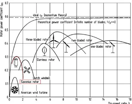
Current Product Blades uses the drag force (21) to convert wind energy into electric energy. The product efficiency can increase by either changing the Blades to use lift force (21) or by making the drag force to be used in more efficient way. The current product working is similar manner to Savonius rotor (19 - figure 3.6 ) .According to different graphs mentioned in different books the Cp of the savories turbine can be obtained slightly greater than 0.1 discouraging the use of Savonius design ,which is later changed into 0.3 in some new researches.
It can be clearly seen in the graph that Darrieus (19 - figure 3.6) rotor and three blade vertical rotor are more efficient then the Savonius rotor but due to need of high amount of speed to start rotating they cannot be used because as mention in factors the product must be able to rotate at low speed. Another disadvantage of using Darrieus design it that it required initial push to start working. However Savonius can be combined with the other type of turbine such as Darrieus to achieve low speed start and good efficiency.
Figure 3.2. Power coefficients of wind rotors of different designs, old research[7]
Figure 3.3. Power coefficients of wind rotors of different designs, new research
3.8 Types of wind turbine
There are many ways by which kinetic energy from wind can be converted in the form of useful energy. Windmill convert wind energy into energy which can be used for milling grain, pump ground water etc. or it can be used to generating electricity as wind turbine.
Wind turbines can be divided into two main types: 1. Horizontal axis wind turbine (HAWT)
2. Vertical axis wind turbine (VAWT)
Figure 3.4. Types of Wind turbine (a) Horizontal axis wind turbine (b) Vertical axis wind turbine [8]
3.8.1 Horizontal axis wind turbine (HAWT)
In HAWT the main rotor shaft rotates horizontally .HAWT are very common and are mostly used for electricity generation. The most common three bladed HAWT uses lift force to rotate .Some kind of yawing system is mostly required to rotate the turbine in the direction of wind. Numerous possible types of HAWT of different forms can be seen in the picture below.
3.8.2 Vertical axis wind turbine (VAWT)
In VAWT the main rotor shaft rotates vertically .VAWT uses drag, lift or both together to rotate. The VAWT utilize wind energy coming from all directions to rotate no yawing system is required unlike HAWT.VAWT which drag type can easily start at it owns at low wind speed otherwise other VAWT like Darrieus required push to start rotating. Numerous different types of HAWT can be seen in the picture below.
Figure 3.7. Several typical types of vertical-axis wind turbines: (a) Darrius;
(b) Savonius;; (c) Solarwind™ ; (d) Helical ; (e) Noguchi ; (f) Maglev ; (g) Cochrane [10]
3.8.3 Advantages / Disadvantages of VAWT
There are various advantages of VAWT which make it good choice to be used for this product. The main advantage of the VAWT here is that it gives feeling of the lamp hence it can be used as decoration lamp. Unlike HAWT the VAWT can use the wind from all direction so no rotation of the blades are required towards the direction of wind which make the design simple and decrease manufacturing cost. Also the main shaft is connected directly to the generator without using any gears which make it less noisy.
The main disadvantage of VAWT is that it required more amount of wind speed to start as comparing to HAWT .It sometime also required push to in order to start rotating at very low speed. So to keep the turbine rotating at low speed its challenging and proper design and form is required.
3.9 Aerodynamic knowledge
3.9.1 Betz limit
Albert Betz the German aerodynamicist tells us about the maximum amount of energy which can be gained from the available wind by ideal rotor .According to Betz limit only 59% of kinetic energy available in wind can be converted into useful energy.
Figure 3.8. Betz Limit [11]
3.9.2 Swept Area
The power generated by turbine linearly depends upon the wind swept area of the turbine. As the swept area increases more energy can be gained from the wind. The swept area is mostly the projected area of the wind turbine shape for example.
For HAWT the swept area can be calculated as
A =𝜋. 𝐷
4 D = rotor diameter.
Also Darrieus vertical axis wind turbine the swept area can be
A =𝜋
2((𝑀𝑎𝑥𝑖𝑚𝑢𝑚 𝑟𝑜𝑡𝑜𝑟 𝑤𝑖𝑑𝑡ℎ 𝑎𝑡 𝑡ℎ𝑒 𝑐𝑒𝑛𝑡𝑒𝑟 ) ⋅ ( ℎ𝑒𝑖𝑔ℎ𝑡 𝑜𝑓 𝑡ℎ𝑒 𝑟𝑜𝑡𝑜𝑟)
[12]
3.9.3 Lift, Drag Forces and Cp
3.9.3.1 Lift force
Lift force is created in direction perpendicular to the oncoming airflow. The force is generated due to the unequal pressure distribution on the surface of airfoil. The large the lift force is the more efficient in the airfoil.
Figure 3.9. Drag and lift forces on stationary airfoil; a,
angle of attack; c, chord [13]
3.9.3.2 Drag force
Drag force is created in direction parallel to the direction of oncoming airflow and it is produce due to both viscous friction forces at the surface of airfoil .The drag force can be decreased by making the surface smooth by either polishing the surface or by adding some paint on the surface. To make an efficient airfoil the drag force should be decrease as much as possible.
3.9.3.3 Coefficient of Power (Cp)
The power coefficient can be defined as
P =𝐸𝑙𝑒𝑐𝑡𝑟𝑖𝑐𝑖𝑡𝑦 𝑝𝑟𝑜𝑑𝑢𝑐𝑒𝑑 𝑏𝑦 𝑡ℎ𝑒 𝑤𝑖𝑛𝑑 𝑡𝑢𝑟𝑏𝑖𝑛𝑒
Electicity avilable the wind
Pt theoretical power to be obtained from wind
Pt =1
2 . 𝜌. 𝑆. 𝑉^3
Where
S = Swept area of turbine
V = Wind Speed ( m/s)
ρ = Air Density ( 1.225 kg / m^3 ) Pa Actual power coming out (wind generator)
Pa =√3 ( V . I + V. I + ⋯ ) 𝑁
I = Current
√3 = for 3 phase generator N= no of readings
Hence,
Cp =Pa
𝑃𝑡
Whereas 59.26 percent is the maximum achievable power coefficient, the Betz Limit. [14][15][16].
3.9.4 Blades Shape
Wind turbines which use lift force to work the blades are made of certain shape known as airfoil. These airfoils define the shape of the blade. There is numerous standards’ way of developing airfoil such as one way developed by “National Advisory Committee for Aeronautics (NACA)”. The airfoil shapes are similar which can found in airplane wings or propeller blades. Normally one or more than one profile combine together to form a blade.
Figure 3.10. Cross section of airfoil [17] 3.9.5 Rotor Solidity
Rotor solidity is ratio between how much area is cover by blades divided by the total area of the turbine. It is mostly written as the percentage of the circumference of the rotor which contains material rather than air. High solidity machines causes more starting torque then low solidity machines and cost more due to large amount of material used for making them while low-solidity machines need to be made with more precision which leads to less difference in costs between Low and high solidity machines.
Wind-mechanical systems have "high-solidity-ratio” and "low-tip-speed-ratio" rotors. These systems start up in very low wind speeds (typically 3-5 mph) and are great for "torque-type" operations, such as pumping, lifting, grinding machines etc.
While the others types i.e. wind-electric systems have "low-solidity-ratio," "high-tip-speed-ratio" rotors. Wind-electric systems start up in moderate wind speeds (typically 3-7 mph - but don't really start making useful electricity until 9-11 mph). [18]
3.9.6 Tip-Speed ratio (TSR )
The speed of the wind turbine blade at its tip divided by the speed of the wind is called TSR. For example, a wind turbine blade tip is traveling at 200 mph (and the wind speed is 50 mph, then the TSR is 4 (200mph /50 mph) which means the tip of the blades is 4 times faster than the speed of wind [19].
TSR =Speed of rotor tip
Wind Speed = 𝑣 𝑉 = 𝜔𝑟 𝑉 3.9.7 Blade count
Number of blades is also one of important things one must know before design a turbine. The numbers of blades are linked with efficiency of the turbine. Increasing the number of blades help turbine to get more power from the wind and stop any air passes thought the gaps but question rises why large wind turbine have only three blades not Four or more ? The reason of using three blades is that when the turbine start rotating fast and the second blade come to quickly at the place of first blade and it will not be possible for it to extract power from the wind because the air is disturbed. So to get power from the wind the blade must come after some time after the first blade has already extracted the power from wind and wind stream lines are no longer disturbed. In large wind turbine four blades give little more efficiency than three blades but the cost goes to much high that’s why they don’t prefer to use it .So there for too many blades don’t help to get more efficiency but they can help to start the wind turbine at low wind speed.
Increasing the number of blades will also cause to much vibration which will also cause the turbine to rotate less efficiently So it’s always important to check what number of blades are required to make the turbine work efficiently.[20]
3.9.8 NACA airfoils
There are numerous types of airfoils available which can be used in the designing of particular aircraft, propeller or wind turbine blades. It’s always a big question to answer which kind of airfoils should be used for
a particular problem. The first ever airfoil was developed after observing the wing of the bird. During 1930s several airfoils have been developed by “National Advisory Committee for Aeronautics (NACA)” which has been successfully using airfoils for general aviation. However it was not simple to design airfoil as numerous parameters such as thickness, location of maximum thickness, leading- edge radius etc. has to be considered while developing the airfoils. To solve this problem the “NASA Langley Research Center” sponsored to develop a computer programs for generation of coordinates for standard NACA airfoils .After
this NACA airfoils can be easily develop and there coordinates can be easily generated. Different software’s are available which helps to achieve this target such as Javafoil. Some of NACA airfoils have 4-digit, 4-digit modified, 5-digit, and 16-series airfoils etc. [21][22]
3.10
Generator
Generator is a device which is used to convert mechanical energy into electrical energy. Wind blades help to rotate generator which create electricity .This energy is later stored in batteries. There is various kind of generator which can be used to generate electricity .The most common used generator is 3 phase generator.
Types of Generator
One phase generator
Three Phase generator (Delta or Star)
Figure 3.11. Three phase generator output [23]
Three phase generator are more efficient than one phase generator by value of √3 =1.73 because the current phase don’t fall to zero. However they are further divide into two more types i.e. Delta and star.
Figure 3.12. Types of three phase generators [24]
The basic difference between Star (also called Wye) and Delta is that the Star configuration generates a higher voltage at a lower current, and delta generates a lower voltage at a higher current. However, total amount of power generated is equal in both configurations.
3.11
Wind Mapping
Wind mapping help to understand the characteristics of the wind .It involves the scaling of wind speed and its distribution. If we know the average annual wind speed of the area it becomes easy to design the product. The Wind mapping helps to understand the minimum and maximum speed which blows though out the year. Height is not an issue here the product is mostly use on the ground. It is must to study to the wind mapping before designing a product for specific area.[25][26]
3.12
Wind Testing
After the form of the product is ready the next step to test how much efficient the form is .The testing is done by different way either by using a wind tunnel or by fan. The wind tunnel also helps to find lift and drag forces created by airfoil of the Blade which help to compare different wing profiles. As the wind tunnel is not available in the university the testing of the product is done by using a fan at different wind speed. Anemometer is used to find different velocities of the wind and tachometer is used to find the revolution of the turbine. Voltages and current are measure by the voltmeter and ammeter respectively.
4 Method
4.1 Understanding Brand Valves
Whenever it comes to design a product for a specific company the First method that applies is to understand the brand Values .The brand values of IKEA are different from the IKEA values .The brand values express what the IKEA Brand stand for from customer point of view. Some of IKEA Brand Values express from “A manual from IKEA systems B.V 2007 “are summarized as under:
“Functional – no fancy Clear – not complicated Honest – not fake Fun – not dull
Smart and thrifty – not extravagant Surprising – not expected
Warm and human – not cold and distant Inexpensive - not expensive
Rebellious - not conformist For the many – not for the few Swedish - and not from anywhere “
4.2 Brainstorming
According to design council the brainstorming can be explained as Brainstorming is a method to create different ideas; it can be solving a problem or creating something totally new. Brainstorming mostly starts with different ideas which become better and better after some time. The brainstorming can be noted down in different ways either in the form of some notes or some doodles or sketches.
It’s a go on process in which different ideas are created , the ideas don’t need to be perfect they help to think outside the box, extending the imagination and seeing the problems in different prospective. There are no rules of brainstorming every idea is welcome and not criticized is allowed.
Brainstorming is mostly done in relax way having refreshments and biscuits is a good and relaxing way for brainstorming. The expectation of brainstorming includes Ideas, Concept sketches, doodles or thumbnail sketches.[27][28]
4.2.1 Idea Tree
Idea tree is a structured way of generating different ideas. Idea tree helps to create flow of ideas connecting with each other in form of continuous branch. To start creating idea tree, write down the subject and then start connecting ideas that are connected with the subject. This process continuous till there is no longer any idea related with the subject. Different colors can be used in the process of creating idea tree. Idea tree helps to understand the complexity of things linked with the subject.
4.2.2 Combine unlikely ideas
From Latin work “cogitate” means “to mix together” .Taking two or more than two ideas and then combining them together .Combing ideas help to generated new ideas which give unexpected and surprising results. Combining unlikely ideas also help to utilize ideas which are independent and are not useful unless they are combined with some other idea.
4.3 Scribble-Say-Slap Brainstorming
This method is performed with the help of group people. Scribble –Say-Slap method helps to see the problem with different people perspective. In this method people generated different ideas related to the problems and write them on a sticky notes and stick on the wall or board by saying them loud. This helps other persons to give more visions and they create more ideas in response. All ideas are welcome in the process .There are not specific rules in this method everyone is welcomed to generated as much ideas possible.
After all ideas are put on the wall or board .They ideas are grouped together .This help to combine all ideas in different small groups. Ideas which don’t fall in the group are treated independently. Voting of different ideas can also be done in this method.
Stationery things required in the process are marker pens, sticky notes (lots of them), flipcharts and a whiteboard or a large sheet of paper.
[29]
4.4 Function Analysis
Functional analysis is a kind of technique which helps to understand the functions of the product in more clear way. In this method the functions are characterized in four different ways such as Primary (P), Necessary (N), Desirable (D), and Unnecessary (U).
Primary functions are the basic functions a product should have while necessary functions are those which a product must perform. Desirable are those function which a product supposed to have in order to make it more preferable .Unnecessary functions are not important functions a product should have but they can be extra features a product can contain.
All functions are summarized in the form of a table .First column tells about the function, second it type i.e. primary, necessary, desirable or unnecessary. Third column tell us about the limits/Uses. [30]
4.5 CAD Modeling
CAD modeling helps to visualize the product form in clearer way. A 3D modeling software is used in this technique. After the sketching phase a product is modeled in CAD software with exact size and proportion. CAD modeling is easy and quick way of visualizing lot of forms. No matter how much difficult the form is its can be easily modeled with this technique.
4.6 Design Selection matrix
A design selection matrix (Pugh chart or Pugh matrix) which help designer to compare different ideas with teach other in a systematically way. The alternative concepts which are obtained by brainstorming are compared with each other in the form of table. Different concepts are chosen and they are weighted on the basis of their properties. The score is given and the net score is calculated to find the best concept. A example of design selection matrix is shown below.
4.7 Physical prototyping
Physical prototyping help to visualize how the product will used or work before going into final version. Prototyping can be done in variety of ways. Sometime prototypes are made with the help of cardboard box by using some glue etc. 3D printing machine could also be possibly be used to make the prototype.
At early stages quick prototypes are done to see quick look or function of the product but after making few quick prototypes and testing them a final prototype can be made. Prototype also helps in the selection of the right material for manufacturing. At early stages the prototypes should not be criticize.
Physical prototyping are also effective way of communicating ideas to others. It’s the best of converting your ideas and thinking and explains to others. If the prototype is some kind of user wearing, it can also give user experience when it’s tested.
For example, if you want to make furniture, in the early stages it can be made by help of foam or card board with the help of hot glue and can be improved later by making it with wood and adding some mechanics if it involve some. Some fabrics can also be used on the surface after finding the right form.
[32]
4.8 Trial and error method
Trial and error method is a technique in which multiple chances and ways are tried at many time to find the right solution or possible close solution. For Trial and error method you first have to know the problem and then different possible ways are tried.
Trial and error is good tool for inventors as they can first imagine the idea and then after though trial and error they can find what they looking for. This method also help to selection for example if you want to selected best material it can be selected after trying different material and finally scan select the best one.
This method also helps to solve problems which are complex in nature and there are multiple chances to get there right solution. However, this technique is not good for problems which don’t five chances for multiple solutions.[33]
5 Approach and Implementation
As discussed in the theoretical foundations, the product efficiency (Cp) can be further increased to quite good amount from 0.1 to 0.3 by improving the current drag blades or by changing the blade into one that uses both drag and lift force .This can help to design attractive and efficient form. To achieve the targets following steps have been taken which are described in the form of the design process. The design process consists of four main phases Research, Analyzing, Conceiving, Drafting and Developing & Optimizing. [34]
Figure 5.1. Design process [34]
CONCEIVING RESEARCHING ANALYZING DRAFTING DEVELOPING OPTIMIZING Market Analysis Project planning Define Target Group Technical demands Environmental impact
Visit to company Windforce.se
Mood Board Idea tree
Group Brainstorming Functional Analysis Testing old model Alternative solutions CAD visualizing Evaluating form CAD Modeling -Blades profiles Manufacturing of different forms
Testing different forms Testing different generators Optimizing form
5.1 Research and Analyzing
The first part of the process is to do the research which involves the gather of information about the product. Lot of parts of research has been mentioned in the earlier part of the report like the Theoretical background which explains the way of working of the product. No doubt engineering as well designing knowledge are required to make the product work in efficient manner however there are lot of other things which also have to be known in order to achieve the targets.
Different activities which are planned during the project can be found in the attachment “IKEA Project planning “
5.1.1 Market Analysis
Wind and sun energy is being used to generate energy for large scale production but not so many products can be found in the market which uses both energies to generate current and use it for outdoor decoration. Different product in the market uses solar energy and used in the garden for garden but mixing the sun energy with wind energy is quite new idea.
5.1.2 Defining target group
The IKEA vision is "To create a better everyday life for the many people."
As IKEA products are for many people and attract people of different age groups. The product SOLVINDEN is used for people who have garden or have balcony to use the product. Product is attractive and
looks fun so people of every age are attracted towards it. ¨
5.1.3 Technical demands
As the product is made of different components which assemble together to form a complete assembly, there dimensions are need to be known before replacing the part with some other new part. For example if the blades have to place by new blades they must fit into the product assembly ,here the technical requirements have to be known before start working .To solve this problem different assembly part were opened and there dimensions were noted down in order make something that’s fits exactly .If the blades are not according to the dimension they will exert pressure on the base and top plates of the product which will cause pressure on the bearing and results in hindrance in the rotation .
Figure 5.2. Technical demands 5.1.4 Environmental impact
The product has good environmental effect as it totally green as it is using the energy from the sun and wind. The LEDs used in the product also safes energy and are long lasting. By making such product
available will help to make the environment safe. No doubt the energy produced by the product is very small but it’s a good step towards the energy saving and green future.
In future material such as liquid wood can be used replace some parts of the product like the blades.
5.1.5 Visit to Company Windforce.se
To gain knowledge about the wind turbine a meeting was arranged on 5th April with Ulf who’s the founder of winforce.se. Some conclusion was noted down after the meeting which can be summarized as under:
Adding many blades can help to start the rotation at low speed but they won’t be efficient as they will the limit the revolution of the product. Good ratio of solidity must be known which allow the product start immediately and also help to achieve good amount of RPM.
The solidity 34% can be a good ratio or a good solidity ratio must be searched for this product.
- Reduce noise ( like owl wings )
- Create small vortex so air can be there for long Wing profile mixture ,use Lift blades with the Drag blades The blade with profile can be dangerous at high speed they can
cut the things but it is possible to make profile in such way to control the rpm, not too much high also not so slow.
Check the old model and try to find right angle for the drag blades, the blades can arranged in more efficient angle.
Check fans for the research.
First stop working on the profile and get the drag blades working with more efficient way and then you can add profiles.
Taper [64] check whether it will help or not.
For lift blades the angle must be 90 degree with the surface in order to make them work.
Use thicker NACA profile at least 24% thickness.
Make straight blades it will be easier to start work and making progress toward the curved blades
Making the blades curved will help to start the lift blades without any push?
Make frame around the turbine to protect people possible?
Check the right place for the placement of the product. Placing the product at wrong place can results in not working of product
The figure 5.3 explain the place where the product should be placed so it can be have maximum wind available .The red color tells about the maximum speed and blue shows the minimum speed. It clears from the picture when block is placed in the way of wind, which creates lot of vacuum and makes the area unsuitable for the product placement.
5.2 CONCEIVING
5.2.1 Mood Board
After understanding the product values the mood board is used which visually explained the style which will be used in developing the design concepts. Mood board also helps to communicate others the overall feeling of the product which are being tried to achieve in the process. Mood board mostly consists of lot of images which are used to express the feeling of the product but in the figure 5.6 many images are blended together to give feeling in form of a image.
Figure 5.5. Mood board
5.2.2 Idea tree
Idea tree is used in the express stream of consciousness by linking the ideas together .The ideas tress helped to understand the complexity of the project and different things which are linked with the project. Idea tree also helped in later stages to do the functional Analysis of the product. The fig 5.7 shows the idea tress done for the product.
Figure 5.6. Idea tree
Different hidden features which are linked with the product form and function and founded by this method like the safety .The product should not rotate so fast that it can cause any kind of damage to people around or produce any kind of reflection or glittering that effect the observer eyes who’s standing beside the product.
5.2.1 Group Brainstorming
Scribble-say-slap brainstorming method is used with different designers in the school and lots of ideas are created. The group brainstorming helped to create some interesting ideas which are later used in the process. During the session some good ideas are marked with red dots. Some ideas like ( Idea 1) rotation in opposite direction ,idea 2
convertible lamp , idea 3 connecting several shapes ,idea 4 organic shape and idea 5 series of lamp were really interesting.
5.2.2 Functional Analysis
Functional analysis of the product is done to understand what things are required be done in the project according to their preference.
Table 1 Functional analysis of product
Function Class Limits/Uses
Energy Efficient P Use maximum wind
energy
Increase Beauty P Look fun
Enable Rotation P Always rotating
Simple Operated P No gears etc.
Generate Power N Generate energy
Care Production N Easy manfacturable
Look Attractive N Fun to see
Care Pollution D Less noise pollution
Own Image D Company image
Energy Consumption D Less usage
Smart Packaging D Enable flat packaging
Facilitate Production D Easy assembled
Care User D Safe to use
Care Surrounding D Care for birds
Material Recycling D Must be able
For many D For everyone
Look Fun D enjoyable
Smart Design D Less volume
Swedish Design D Not from anywhere else
Warm Human D Not distanced
Stable Design D Less vibration
5.2.3 Testing old Product
To start working on the new concept few experiments are done on the exciting product to check what improvements can be done in the design. Lot of readings has been taken at different speeds which are
summarized into the form of table shown below.
Table 2 Experimental results of current product Wind Velocity (m/s) Revolution (rpm) TSR (V)Voltage (max) (I) Current mA (max) Actual Power(√3*V*I) Power theoretical Coeff Power (cp) 1 2,18 80,71 0,59 1,6 12 0,033 0,322 0,1 2 2,98 114 0,61 2,2 19 0,07 0,822 0,08 3 3,97 157,9 0,63 3,1 30 0,16 1,95 0,08 4 4,28 155,2 0,58 2,8 28 0,135 2,44 0,05 5 5,1 152,4 0,5 2,9 26 0,13 4,1 0,03 6 6,36 205,4 0,52 3,6 44 0,274 7,99 0,034 7 7,3 249 0,55 4,16 47 0,338 12,1 0,032
Figure 5.8. Power vs. Velocity graph
The graph in fig 5.9 shows that as the velocity of wind start increasing the power generated by the turbine also start increasing but as it reach 4 m/s it start falling and it keeps falling till 5 m/s and after that the power generated start increasing again. The fall in generation happen due to vibration of the structure. It very important for the structure to generated good amount of power at low speed because most of the time the wind blow from 2 to 5 m/s in normal day. The detail calculation for these
0 0.05 0.1 0.15 0.2 0.25 0.3 0.35 0.4 0 1 2 3 4 5 6 7 8 P O WE R (W ) Velocity ( m/s )
Power VS Velocity
Figure 5.9. Power vs. RPM
Figure 5.10. TSR vs. Velocity
Same effect is observed in the TSR and RPM of the product which start increasing at 2 m/s and then falls down for a while and then start
increasing again. If we see the graph between Cp vs TSR and compare with fig 3.1 the graph should increase and it should go till maximum Cp and it should start coming down as the TSR increase but if we see fig 5.12 the graph start from Cp 0.1 and then its keeps falling which shows that not only the blades the structure has to be improved to in order to make the Cp to keep increasing.
0 0.05 0.1 0.15 0.2 0.25 0.3 0.35 0.4 0 50 100 150 200 250 300 P O WE R (W) RPM
Power VS RPM
0 0.1 0.2 0.3 0.4 0.5 0.6 0.7 0 1 2 3 4 5 6 7 8 TS R Velocity (m/s)TSR VS Velocity
Figure 5.11 Coefficient of power (Cp) vs. TSR graph
Conclusion from the experiment: Some conclusions from the testing of existing model can be summarized as:
1. Due to vibrations in the model the TSR goes down first and then later it goes up as the wind velocity (v) increases
2. As the velocity increases the RPM keeps on increasing showing that it’s possible to get more energy from wind.
3. Increasing the No of Blades will help TSR to go further beyond 0.63. 4. Increasing No of blades will also help to move vibration zone further at high wind speed then more energy can be gained at low speed. 5. All readings are taken from one directional wind ( wind coming from one direction ) The product will perform more efficient in the outdoor environment.
Improvements Required:
1. Vibration can be reduced by making the Base of the Product Stronger.
2. Reduce vibration by adding some hub on the bottom.
3. Reduce vibrations by making the blades circular and by joining them 1-2 Or 1-3.
4. Adding more legs to make the structure stable or Increase thickness of the rod.
5. Putting the generator in the base can help to reduce the vibrations.
0 0.02 0.04 0.06 0.08 0.1 0.12 0 0.1 0.2 0.3 0.4 0.5 0.6 0.7 Cp TSR
Cp Vs TSR
5.2.3.1 Testing method
A proper testing method and testing instruments like anemometer, tachometer, millimeter(voltage and current )are used to measure wind speed , RPM , voltage and current respectively. All the readings are taken when load ( battery) is connected to the circuit.
Figure 5.12 Anemometer, tachometer and millimeter
To measure the readings first the anemometer is used which tells about the wind velocity .Tachometer is used to measure the RPM of product which is rotating at that particular wind speed. When generator starts rotating with the wind, millimeter is used to measure voltage and current across the wire. Wind is artificially generated by using a large size fan. The speed of wind can be varied by varying the speed of the fan.
Figure 5.13 Product Generator wires
Voltage(AC) is measured by connecting the millimeter in parallel while the current (AC) is measure by connecting the millimeter in series in the circuit. As the generator is three phase ,three wires comes out of the generator any two wires can be used to measure the voltage and
current. If the cover is removed from the top of the product ( as shown in fig 5.14) red, black and blue wires can be seen. Black and red wire are used to measure voltage and current in the experiment.
The voltage and current coming out from solar cell can be found in similar manner.
5.2.4 Alternative solutions (Concept sketches)
Different concepts are sketched without any limitation or constrain to check the different possible form of the product. Some of sketches are done after the completion of research and some of them are done before. The ideas were mostly divided into two types drag products and mixture of drag and lift products. According to the aerodynamics
knowledge the drag devices have more chances of working at low speed then the other types so many of sketches are according to the drag type. Unlikely ideas are also combined together in later stages and CAD software is used to explore them.
The main parts of the product like luminaire, generator and base rod etc. are known so therefore they are sketched in the about all sketches to understand there placement. Some sketches are used only done to understand the new form of the product. As the product is to be used in garden so it organic shape like flower or tree was also important so it fit perfectly in the surrounding.
5.2.1 CAD Visualizing
After different forms are sketched on paper they are visualized using CAD software to understand them in more clear way. CAD visualizing is done in quick way no proper dimension of parts are done in CAD
software only different proportions are considered forms which are complex and not clear were not taken into the next step. As the form has to work in efficient way and it should be easy to manufacture there limitation were applied and only few of forms were taken to the next step to be explored further. The designed marked with red are lift + drag type turbines and the rest are the drag type devices.
5.2.1 Evaluating Forms
After doing the CAD visualization of different forms few forms were selected and there evaluation was done. As there are numerous forms which can be manufactured and tested to check their performance but to make the target achievable in limited available time the evaluation of these form were done on the basis of theoretical knowledge and
previous knowledge. According to different criteria Design 1 and 3 are selected from lift + drag type device and Design 4 and 5 from Drag type device.
5.3 Drafting
After choosing the possible four forms from “forms Evaluation” the forms are designed one more time in detail using CAD software .The swept area, number of blades ,TSR and some other features which are assumed. As everything has to be fit exactly into old model so proper dimensions of old models are gathered which are taken previous in “technical demands”.
Two main types of form are Lift + drag and drag forms both have their own way of construction and working. Lift+drag uses both lift and drag forces to work while the drag form use only the drag force to work.
5.3.1 CAD Modeling
5.3.1.1 Lift + drag form
The difference between Lift + drag form from drag and lift type is that it uses first the drag force to start and then lift force to help to gain more revolution. The drag force is created by the curved shape of the blades. As the blades are not straight which create a hindrance for air which help to create push to the blades. Also the blades are made in helix shapes which help to create all the motion toward center results in providing stability to the structure.
The blades are connected 1-2 which means that first snap fit is
connected to second snap fit of top plate. The connection can be made more curved by connecting 1-3 , which will help to create more drag then 1-2 connection.
To make the Lift forces work the profile has to be 90 degree to the circular plate which can be seen in figure 5.21. If the profiles are not place at 90 degree the blades are not able to create lift forces. If the blades are made straight it become easy to keep the blades profiles 90 degree to the circular plate but in helix it quite complex. Eight blades are used in both Lift + drag forms. No doubt more blades can create more drag but due to area limitation more blades are not able to fit in that area. Possible space is required between the blades so the air can pass through them and hit the blades in front to create a drag force.
As there are a lot of profiles which can selected for the blades but the best one can only found after testing. Selecting the profile in a complex phenomenon ,to solve this problem different type of profiles are selected for the first test and then optimization of it is done in later stages.
Figure 5.18 Lift + drag forms
5.3.1.2 Blades profiles
The blades in the current product don’t use any kind of wing profile design they are mostly half circle or little curved inside so the air can stay there longer and push the blades but when it comes to Lift type blades have to designed according to specific design. NACA airfoils are used in the developing the design of the blades.
As there are numerous types of NACA profiles only four digit NACA profiles are used in the process to decrease the complexity of the project .First different x, y and z points of NACA profile are generated and then they are imported into Solidworks to create profiles design. These profiles are then used to make blades.
Figure 5.20 Blades construction
Increasing the profiles thickness can help to get more lift from the blades but by increasing the thickness it will also increase the weight of blades and will also not allow the light to pass through them therefore using a thick profile is not a good idea.
Java foil software is used to calculate lift and drag coefficient at different angles in figure 5.23 .Figure 5.23 also tells about different types of profiles and there length and thickness. Symmetric profile and unsymmetrical profile both are used to check which profile give best results. Mostly symmetric profiles are used in the VAWT available in market today, the reason of choosing deep chamber unsymmetrical profile is that it may help to capture wind and generate more drag then the symmetric profile. No doubt both profile will also help to create lift force.
Table 4 Blade profile selections
5.3.1.3 Drag form
As two types of drag forms are also chosen from “evaluating form” one of it has straight blades and other have the curved as shown in the figure 5.24 .The blades are connected straight with top and bottom plates no 1-2 or 2-3 connection are made in this stage.
In drag forms no NACA profiles are used which make the construction of the blades little simpler. The blades consist of surface which air hit and create push to rotate. Blades are aligned at certain angle so that they can capture most amount of wind. As discussed in the factors the product has to must start rotating at low speed this can achieve by adding more blades which will allow capturing more wind. Unlike the Lift + drag form there is possibility to add more blades .Adding 12 or 16 blades can help to capture more wind. Two sets of models are designed one with 12 blades with angle of 30 between each blade and 16 blades with angle of 22.5 between them.
Blade Profile Selection
Profiles Length(L) Thickess(T) Cl max Angle (degree)Cd max Angle
NACA0008 50 4 0,829 8 0,69429 45 Profile Picture:
NACA0009 54 4,86 0,825 12 3,05 41 NACA0010 54 5,4 0,888 13 3,445 45 NACA0011 54 5,94 0,95 14 3,25 45 NACA0012 54 6,48 1,018 15 2,67 45 NACA0013 54 7,02 1,085 16 2,17 45 Calculation: NACA0014 54 7,56 1,154 17 1,93 45 NACA0008 Tickness limitation L = 50 NACA9312 54 6,48 2,2 13 4,9 83 T = 50 * .08 = 4mm NACA8412 54 6,48 2,213 13 4,8 83 NACA9412 54 6,48 2,221 12 4,8 83 NACA8512 54 6,48 2,04 10 4,9 79 Blade placment Note:
(1) Cl = Coefficient of lift Cd = Coefficient of Drag
(2) As the Profile become thickner the Coefficient lift increases but the weight of the Blades also increases with it. (3) Software : JAVAfoil , Re=1O^5 , Air Desity = 1.225
S y mm et ri c De ep Ch amb er U n sy mm et ri c
![Figure 3.1. Relationship between sense, meaning and actions [5]](https://thumb-eu.123doks.com/thumbv2/5dokorg/5397484.138027/16.893.228.662.199.561/figure-relationship-sense-meaning-actions.webp)
![Figure 3.2. Power coefficients of wind rotors of different designs, old research[7]](https://thumb-eu.123doks.com/thumbv2/5dokorg/5397484.138027/18.893.192.685.582.974/figure-power-coefficients-wind-rotors-different-designs-research.webp)
![Figure 3.5. Various concepts for horizontal axis turbines [9]](https://thumb-eu.123doks.com/thumbv2/5dokorg/5397484.138027/20.893.196.705.333.946/figure-various-concepts-horizontal-axis-turbines.webp)
![Figure 3.6. Various concepts for vertical axis turbines [9]](https://thumb-eu.123doks.com/thumbv2/5dokorg/5397484.138027/21.893.194.715.326.1002/figure-various-concepts-vertical-axis-turbines.webp)

![Figure 3.9. Drag and lift forces on stationary airfoil; a, angle of attack; c, chord [13]](https://thumb-eu.123doks.com/thumbv2/5dokorg/5397484.138027/24.893.199.726.114.320/figure-drag-forces-stationary-airfoil-angle-attack-chord.webp)
![Figure 3.12. Types of three phase generators [24]](https://thumb-eu.123doks.com/thumbv2/5dokorg/5397484.138027/28.893.272.616.106.402/figure-types-phase-generators.webp)