Nr V179 1992
Titel: Polymerbitumenmattor. Jämförande
undersoknlng
av provningsmetodik vid bestämning av
lågtem-peraturflexibilitet, värmebeständighet och
mjukpunkt
Författare:
Ylva Colldin, Åsa Nilsson
Avdelning:
Vägavdelningen
Projektnummer:
4203802-6, 4231201-7
Projektnamn:
Broisoleringsmaterial
Uppdragsgivare: VTI, VV
Distribution:
fri
div
Väg-och
Trafik-/
Inst/tutet
1 . ORIENTERING
2 . PRÖVNING
2.1
Undersökta produkter
2.1.1
Flexibilitet vid låga temperaturer
(böjtest) 2.1.2 Värmebeständighet (avrinning)
2.1.3
Mjukpunkt
REFERENSERBILAGOR
10
16
kationer och krav för polymermodifierade bitumenmattor för
broiso-leringsändamål. Det aktuella provningsprogrammet omfattar
karaktä-riserande provning (av isoleringsmattan), provning av polymerbitumen
och primer liksom funktionell provning av isoleringssystemet.
Prov-ningsprogrammet (bilaga 1) ingår i bronormens avsnitt nr 6. Godtagna
produkter finns upptagna i avsnittet nr 8. För godtagen produkt
krävs, förutom genomförd laboratorieprovning med acceptabelt
resul-tat, att provläggning utförts på minst två provbroar.
Laboratorie-provning utförs vid VTI (1, 2).Inom det europeiska standardiseringsorganet CEN (Comité Européen de
Nonmalisation) utarbetas förslag till Europastandard. TC 254
"Flex-ible sheets for waterproofing" behandlar bl a provningsmetodik för
polymerbitumenmattor.
I syfte att anpassa vissa av de i det svenska provningsprogrammet
in-gående provningsmetoderna till föreliggande CEN-förslag, har
jämfö-rande provning utförts vid VTI. Parametrar som behandlas i denna
un-dersökning är:
- lågtemperaturflexibilitet (böjtest)
-
värmebeständighet
-
mjukpunkt.
2 . PRÖVNING
Följande provningsmetoder har jämförts:
- Lågtemperaturflexibilitet. Manuell böjtest enligt Bronorm 88
(bi-laga 2a) jämförs med maskinell provningsmetodik enligt CEN-förslag
(bilaga 2b).
provkroppar jämförs, liksom uppgjutning i standardringar
res-pektive engångsringar.
2.1
undersökta produkter
I undersökningen ingår totalt 24 polymermodifierade bitumenmattor,
varav 23 med SBS och en med APP. Produkterna kommer från ett tiotal
tillverkare i Sverige,
Danmark, Tyskland och Frankrike.
Allmänt gäller för de undersökta produkterna:
Polymerhalten är cirka 10-15 vikt-% för de SBS-modifierade
mattor-na och cirka 30 vikt-% för den APP-modifierade.-
Stommen är av polyester eller polyester och glasfiber och
impreg-nerad med oxiderad bitumen eller polymermodifierad bitumen.
Stom-mens totalvikt är cirka 200-300 g/m2.
-
Fyllmedlet är som regel kalkstensfiller. Halten är mindre än
35 vikt-%.
Mattans ovansida är sandad, talkad eller granulatbelagd.
Pro-
Polymer
Stomme
Fyllmedel
Ovanyta
Tjocklek
Vikt
dukt
Total Under
stomr
men
(mm)
(mt)
(kg/m2 )
A
SBS
5,0
3,5
5,94
B
SBS 13%
Polyester 1809
5,0
2,3
5,80
C
SBS
Polyester
Kalksten
Sand
5,1
3,0
6,41
D
SBS 14%
Polyester 300g
Kalksten 32%
Sand
5,0
2,4
5,68
E SBS 12% Polyester 200g Kalksten Sand 5,2 3,0 6,29
Glasfiber 509
F SBS 11% Polyester 2509 Kalksten 30% Sand 5,0 3,0 6,35
SBS 12%
Polyester 2009
Kalksten
Sand
5,0
3,2
6,38
Glasfiber 509
H
SBS 14%
Polyester 2509
Kalksten 34%
Sand
5,0
3,0
6,07
SBS 14%
Polyester 2509
Kalksten 33%
Sand
5,3
3,2
6,82
J
SBS 12%
Polyester 2009
Kalksten
Sand
5,0
1,8
-Glasfiber 509
SBS 11%
Polyester 2509
Kalksten 30%
Sand
5,5
3,6
-SBS 11%
Polyester-
Kalksten
Granulat 5,1
3,0
7,17
glas 2209
M SBS 14% Polyester 2509 Kalksten 33% Sand 5,2 3,0
-N
SBS 14%
Polyester 2509
Kalksten 33%
Sand
5,1
2,9
-O
SBS 14%
Polyester 2509
Kalksten 32%
Sand
5,0
3,0
-P
SBS 15%
Polyester 2509
Skiffer 30%
Sand
5,1
3,8
5,52
Q
SBS 14%
Polyester 2509
- 0%
Talk
4,6
-
4,70
R
SBS 13%
Polyester 1859
Fältspat 25%
Sand
4,4
-
5,41
S
SBS 14%
Polyester 1809
- 0%
Talk
4,6
-
4,66
T SBS Polyester 2009 Sand 28% Sand 4,7 2,8 5,69
U SBS Polyester 1809 - 0% Talk 4,9 2,9 4,75
V
SBS
Polyester 2509
- 0%
Granulat 4,3
1,5
5,18
(skiffer)
SBS
-
-
-
-
-
lera hur väl polymermodifieringen utfallit. Provningen anses också
(efter värmelagring) ge värdefull information om produktens
åldrings-egenskaper.
"Traditionellt" utförs provningen manuellt med hjälp av dorn
(böj-platta), t ex i enlighet med tysk (DIN 52123 (3, 4)), schweizisk
(SIA 281, 1983 (5)) eller österrikisk (ÖNORM B 3646 (6))
provnings-metod. Enligt föreliggande CEN-förslag utförs provningen maskinellt
med hjälp av speciell böjtestutrustning.
Vid provning enligt provningsprogram i Bronorm 88 utförs höjningen
manuellt i kylrum, med luft som kylmedium (se metodbeskrivning i
bi-laga 2a). Succesivt har emellertid en övergång till provningsmetodik
enligt CEN (bilaga 2b) skett. Jämförande provning har härvid utförts
både manuellt samt med maskinell provningsutrustning, s k BDA-Bending
Tester (kylmedium etylenglykol och vatten, 1:1). BDA-Bending Tester
har utvecklats och tillverkats vid BDA (Buro Dakadvies) i Gorinchem,
Nederländerna. Utvecklingsarbetet har skett i
nära samarbete" med
CEN TC 254.
Jämförande provning har utförts för totalt tjugo produkter. Icke
åld-rat prov har undersökts samt prov som värmelagåld-rats vid 70°C.
Provtagning (antal prov), provberedning med värmelagring samt
bedöm-ning och utvärdering av provbedöm-ningsresultat har skett i
överensstämmel-se med provningsmetodik i bilaga 2a. Provning har utförts i steg om
5°C. För icke värmelagrat prov har, i enlighet med
metodbeskriv-ningen, provbitar utskurna både i längd- och tvärriktning, provats.
För värmelagrat prov utförs böjtest endast i längdriktning.
Erhållna provningsresultat framgår av tabell 2.
Av totalt 76 jämförande provningar har samma resultat erhållits i 70%
av fallen (53 stycken). För övrigt skiljer sig provningsresultaten
endast i två fall med mer än "ett steg" (5°C). Ingen systematisk
Dessutom kan konstateras att böjtest med BDA-Bending Tester ger
bätt-re bätt-repeter- och bätt-reproducerbarhet än vid manuell böjtest samt snabbabätt-re
resultat. Vid VTI utförs böjtest idag endast med BDA-Bending Tester.
Produkt
Flexibilitet efter vårmelagring (°C)
Manuell böjning/EDA Bending Tester
0 mån
0 mån
3 mån
6 mån
T L L LD*
-25/-25
§-30/5-30
5-30/-25
-15/-15
E**
-25/-25
-25/-25
-15/-15
-5/-15
F
-25/-20
§-30/-25
-15/-15
-lO/-lO
G
-25/-20
-20/-20
-10/-10
-5/-5
H
-25/3-30
5-30/5-30
-25/-25
iO/iO
I
5-30/5-30
3-30/5'30
-15/-20
-15/-15
J**
-20/-20
-20/-20
--
--K
-15/-15
-15/-15
--
--L
-20/-20
-20/-15
-15/-10
-5/-10
M
-25/-25
-25/-25
-20/-20
-15/-15
N
-25/-25
-25/-25
-20/-20
-20/-20
O
5-30/-25
-25/-25
-20/-20
-15/-20
P**
-25/-25
-25/-20
-lO/-lO
:0/:0
Q
5-30/5-30
5-30/5-30
5-30/5-30
+15/+15
R
3-30/5-30
5-30/5-30
-5/-5
+10/+5
S
5-30/5-30
§-30/5-30
5-30/-25
+10/i0
T
3-30/5-30
5-30/5-30
§-30/-25
iO/iO
U
-20/-20
-25/-20
-15/-15
-10/-10
V
-25/-25
5-30/-25
-10/-15
-10/-10
Y
-20/-15
-20/-15
-5/-10
-5/-5
*)
Böjradie: 10 mm
på flytbenägenhet och formförändring under värmepåverkan.
Poly-merbitumenets flytegenskaper har avgörande betydelse för
provnings-resultatet liksom eventuell inkompatibilitet mellan
polymerbitumen-skikt och impregneringsbitumen. I mindre utsträckning inverkar också
mattans tjocklek, stommens typ och placering samt (i förekommande
fall) mängd och typ av granulater.
Vid provning enligt provningsprogram i Bronorm 88 utförs
avrinnings-test enligt metodbeskrivning i bilaga 3a. Provningen utförs vid en
specificerad temperatur (100°C) varvid, enligt bronormens krav, ingen
avrinning bör uppstå (<0,5 mm vid visuell bedömning). Metodiken
över-ensstämmer med t ex DIN 52123, SIA 281 (1983) och ÖNORM 3646. Enligt
föreliggande CEN-förslag (bilaga 3b) har emellertid den aktuella
provningsmetoden modifierats med avseende på
upphängningsanordning
och "avläsningsförfarande". Dessutom föreslås att
avrinningstempe-ratur anges, dvs den tempeavrinningstempe-ratur vid vilken provets avrinning uppgår
till 2 mm.Jämförande provning har i denna undersökning utförts för femton
pro-dukter. Provningen avser en provningstemperatur, lOO°C (i enlighet
med metod i bilaga 3a). De två använda provningsmetodikerna skiljer
sig från varann med avseende på provberedning, upphängning och sätt
att avläsa provets avrinning. I det ena fallet (bedömningsmetoden)
anges om provet har runnit (>0,5 mm) eller ej (<0,5 mm). I det andrafallet (mätmetoden) anges avrinningen i mm, uppmätt som.maxima1t
avstånd till en referenslinje mitt på provet (i enlighet med
CEN-förslag i bilaga 3b).
Erhållna provningsresultat anges i tabell 3.
I de fall (4 stycken) produkten med bedömningsmetoden erhållit
om-dömet ingen avrinning (<0,5 mm), har uppmätt resultat med mätmetoden
varierat mellan 0,2 och 1,1 mm. I två gränsfall (50,5 mm) har
mot-svarande mätvärden varit 0,7 och 1,1 mm. I de fall (9 stycken) provet bedömts rinna (>0,5 mm) har motsvarande mätvärden varierat mellan 0,8(<O,5 mm) vid 100°C. Detta krav anses, efter utförd undersökning,
motsvara mätvärdet <1 mm.med mätmetoden.Provning med mätteknik enligt föreliggande CEN-förslag är att
före-draga framför visuell bedömningsmetodik, som i vissa fall kan göra
laboranten mycket tveksam i sin bedömning. Vid VTI utförs
avrinnings-test idag med hjälp av mätmetodik enligt CEN-förslaget. Aktuell
änd-ring m a p provningsmetod och krav föreslås bli införd vid nästa
re-videring av bronormen.
Produkt
Avrinning (mm)
Bedömnings-
Måtmetod
metod
A
>0,5
1,2
E
>0,5
12
D
>0,5
1,1
E*
50,5 (gränsfall)
0,7
F
<0,5
0,6
G
>0,5
0,8
L
>0,5
1,1
M
>0,5
2,0
N
>0,5
1,0
0
>0,5
1,3
P 50,5 (gränsfall) 1,1T
>0,5
25
U
<0,5
0,6
V
<0,5
0,2
Y
<0,5
0,2
2.1.3 Mjukpunkt
Mjukpunktsbestämning utförs ofta för karaktärisering av bitumen och
polymerbitumen. Vid polymerinblandning ökar bitumenets mjukpunkt. För
SBS-modifierade bitumenmattor ligger polymerbitumenets mjukpunkt på
cirka 100-130°C. För AFP-modifierade bitumenmattor är mjukpunkten
cirka 140-150°C. Vid värmelagring sjunker mjukpunkten som regel för
SBS-bitumen medan den AFP-modifierade produktens mjukpunkt påverkas i
mindre utsträckning.
Mjukpunktsbestämning för polymerbitumen utförs
somregel i enlighet
med provningsmetodik framtagen för icke-polymermodifierad bitumen.
För polymerbitumen är emellertid provberedningen en mycket känslig
del i metoden. Oförsiktig uppvärmning av provet kan få till följd att
polymeren bryts ner varvid mjukpunkten sjunker. Som extremt exempel
kan nämnas att prov som uppvärmts i degel över gaslåga under tio
mi-nuter till kraftig rökutveckling, uppvisat en mjukpunktsförändring på
85°C (från cirka 120°C till mindre än 35°C)
Olika provberedningar jämförs
Provberedning med utstansning av prov har undersökts i avsikt att
finna ett provberedningsförfarande som i minsta möjliga utsträckning
påverkar provet. Provberedning med utstansning av prov har således
jämförts med "konventionell" provberedningsmetodik. Konventionell
provberedning innebär i detta fall uppvärmning och uppgjutning av
prov i enlighet med metod i bilaga 4, som enligt tidigare utförda
tester vid VTI givit relevanta mjukpunktsresultat samt god
repeter-och reproducerbarhet.
Vid provberedning med utstansning tas svetsbitumenskikt ut enligt
provningsmetodik i bilaga 4. Flera skikt lägges därefter ihop (för
att få en tjocklek motsvarande mjukpunktsringens), varefter prov
stansas ut med hjälp av varm (200°C) mjukpunktsring.
Materialöver-skottet skäres slutligen bort, då provet svalnat cirka 30 minuter.
Jämförande provning, med gjutet respektive stansat prov, har utförts
för icke värmelagrad produkt samt för produkt som värmelagrats vid
70°C. Erhållna resultat för totalt 17 produkter (102 bestämningar)
redovisas i tabell 4.För icke-värmelagrad produkt har god överensstämmelse mellan
prov-ningsresultat erhållits. För mer än hälften av provningarna är
skill-naden i mjukpunktsresultat il°C och endast i 3 fall av 17 större än
3°C.
För värmelagrad produkt har provberedningen däremot haft mer
av-görande betydelse för mjukpunktsresultatet, och skillnaden i
mjuk-punkt ökat med lagringstiden (3 respektive 6 månader) för mer än
hälften av produkterna. Provberedning med stansning har för
värme-lagrad produkt som regel medfört högre mjukpunktsresultat (upp till
13°C, för produkt C). Produkterna Q, R och T har oberoende avprovbe-redning erhållit ungefär samma mjukpunktsresultat. Värmelagringens
inverkan på mjukpunktsresultatet (mjukpunktsförändringen) blir mindre
vid utstansning av provkroppar än vid konventionell provberedning.
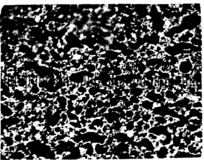
I de fall stora skillnader i mjukpunktsresultat erhållits vid
va-rierande provberedning (t ex för produkt G) har även påtagliga
skill-nader med avseende på polymernätverkets struktur noterats vid
fluor-escensmikroskopisk undersökning (se figurerna 1-4).
Efter utförd undersökning kan konstateras att provberedning med
ut-stansning inte är att föredra framför konventionell provberedning.
Värmelagrat utstansat prov kan variera mycket med avseende på
ho-mogenitet. Detta kan bero på ansamlingar av bitumenkomponenter mot
mattans ytskikt eller mot stommen samt förändringar i zoner mellan
skikt av svetsbitumen (provberedningen).
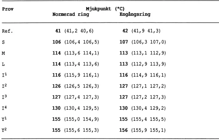
Möjligheten att använda engångsringar undersöks
Enligt provningsmetod i bilaga 4 (MBB 38-82) föreskrivs normerade
mässingsringar av specialtillverkad typ. På marknaden finns
emeller-tid billiga engångsringar i lättmetall av motsvarande dimension.
Möj-ligheten att använda engångsringar vid rutinmässig provning har
un-dersökts. Syftet har i huvudsak varit att minska analystiden samt
har utförts för tio produkter. I inget fall har erhållen
resultat-skillnad uppgått till mer än 1°C. Resultaten redovisas i tabell 5.
Erhållna resultat indikerar att den typ av engångsringar som använts
i undersökningen, vid behov kan ersätta normerade ringar vid
mjuk-punktsanalys av polymerbitumen.
Tabell 4 Mjukpunkt för undersökta isoleringsmattor. Två olika
prov-beredningsmetoder.
Produkt
Mjukpunkt (°C)
Mjukpunktsskillnad (°C)
Gjuten/Stansad
beroende på provberedning
0 mån
3 mån
6 mån
0 mån
3 mån
6 mån
C
130/130
121/130
110/123
0
9
13
D
130/132
117/120
109/118
2
3
9
E*
136/134
128/131
115/123
2
3
8
F
131/132
121/130
113/123
1
9
10
G
134/130
121/130
110/121
4
9
11
H
122/126
109/114
105/112
4
5
7
I
132/135
124/134
109/120
3
10
11
M
120/121
114/122
103/110
1
8
7
N
125/126
119/127
108/115
1
8
7
O
122/122
118/124
107/114
0
6
7
Q
130/130
108/111
104/107
0
3
3
R
116/117
110/109
106/105
l
1
1
S
129/128
106/110
104/110
1
4
6
T
118/117
112/112
105/105
1
O
0
U
132/135
115/123
92/101
3
8
9
V
127/132
115/122
96/105
5
7
9
X
136/136
121/130
103/114
0
9
11
Tabell 5
Mjukpunkt för undersökta isoleringsmattor. Olika
mjuk-punktsringar.
Prov
Mjukpth (°C)
Normerad ring
Engångsring
Ref.
41 (41,2 40,6)
42 (41,9 41,3)
S
106 (106,4 106,5)
107 (106,3 107,0)
M
114 (113,6 114,1)
113 (113,1 112,9)
L
114 (113,4 113,6)
113 (112,9 113,9)
11
116 (115,9 116,1)
116 (114,9 116,1)
I2
126 (126,5 126,3)
127 (127,1 127,2)
I3
127 (127,4 127,3)
127 (127,2 127,3)
I4
130 (130,4 129,5)
130 (130,4 129,2)
Y1
155 (155,0 154,9)
155 (155,4 155,5)
Y2
155 (155,6 155,3)
156 (155,9 155,1)
Mikroskopibild av prov T. Provet har värmelagrats 6 månader
vid 70°C och sedan gjutits upp i mjukpunktsring enligt
kon-ventionell provberedning.
Fi ur 2Mikroskopibild av prov T. Provet har värmelagrats 6 månader
vid 70°C och sedan stansats ut i mjukpunktsring.
Figur 4
Mikroskopibild av prov G. Provet har värmelagrats 6 månader
vid 70°C och sedan gjutits upp i mjukpunktsringar enligt
konventionell provberedning.
läçgdhvk JS*,a
W . .
: 7355321
';1J;?a;4u
*i
_
.I'5;
,NY l Alt, afA/.. 'V ih 1) , ._ .i #1*år
Figur 5
Mikroskopibild av prov G. Provet har värmelagrats 6 månader
REFERENSER
(1)
(2)
(3)
(4)
(5)
(6)
Bronorm 88, Vägverket, Serviceavdelningen Väg- och
Brokonstruktion, Borlänge 1989, 406 PB 30-A 89:324.
Waterproofing of Concrete Bridges. Characteristic and
performance testing of polymer bitumen sheets,
Licen-tiate Thesis 1991:13L, Tekniska Högskolan i Luleå,
1991.
ZTV-Bel-B Vorläufige zusätzliche technische
Vor-schriften und Richtlinien für die Herstellung von
Brückenbelägen auf Beton; Teil 1 Dichtungsschicht aus
einer Bitumenschweissbahn; Teil 2 Dichtungsschicht
aus zweilagig aufgebrachten Bitumendichtungsbahnen;
Teil 3 Dichtungsschicht aus Flüssigkunststoff, 1987.
Technische Prüfvorschriften für Brückenbeläge auf
Beton mit Dichtungsschicht aus einlagigen
Bitumen-schweissbahnen nach ZTV-BEL-B 1/87. Grundprüfung,
Bundesanstalt für Materialprüfung (BAM), Berlin 1990.
SN 564 281 SIA 281 Polymer - Bitumen Dichtungsbahnen
(PBD), 1983.
ÖNORM B3646 Dach- und Abdichtungsbahnen aus Bitumen
ISOLERINGSMATTOR FÖR FUKTISOLERING AV BETONGBROAR
-POLYMERBITUMENMATTOR
.
Specifikationer och krav
Isoleringsmattan skall bestå av en armerande stomme med
polymerbitu-men på båda Sidor. Stompolymerbitu-men skall vara fullständigt genomimpregnerad
med bitumen och i svetsbara mattor vara placerad i mattans övre del så
att minst 3.0 mm utgör svetsbar bitumen under stommen.
Följande skall uppges av tillverkaren:
Bitumen
Polymer:
Typ, halt och fabrikat
Fyllmedel:
Typ och halt
Stomme:
Typ, Vikt, fabrikat och impregneringsbitumen.
Tillverkaren skall också lämna upplysning som Vid hantering av
isoleringsmattan
kan
vara
av
betydelse
från
hälso-
eller
miljöskyddssynpunkt.
Kompatibilitet skall råda mellan de i bitumenmattan ingående
material-en och med de material som bitummaterial-enmattan i brokonstruktionmaterial-en kan
komma i kontakt med. Isoleringen skall vidare tåla beläggning med
gjutasfalt.
Svetsbar isoleringsmatta, Självklistrande matta eller isoleringsmatta
som klistras med polymerbitumen skall uppfylla de i tabellerna 1-3
speCificerade kraven.
For
isoleringssystem
bestående
av
dubbla mattor,
varav
en
skyddsmatta. galler l stort sett kraven i. tabellerna 1 och 2 for varje
matta. For "skyddsmattan" kan dock lagre värden m.a.p. provning l, 3
och 5 i tabell 1 godtas. Provning enligt tabellB utförs aven på
"systemet" av mattor. Vidhäftningskravet : 1.0 N/mm2 gäller då även
Pr
ovn
in
g
K r a v K o m m e n t a rl.
Tj
oc
kl
ek
_>_
5.
0
m
m
En
sk
il
t
mät
vär
de
får
avvi
ka
me
d
i
0.
5
m
m
fr
ån
no
mi
ne
ll
t
kr
avvär
de
.
Kr
ave
t
gäl
le
r
exk
lus
ive
gr
an
ul
at
.
2.
Vi
kt
pe
r
yt
en
he
t
An
gi
ve
s
Up
pm
ät
t
me
de
lvär
de
får
avvi
ka
m
e
d
i
10
%
fr
ån
no
mi
ne
ll
t
vär
de
.
För
ma
tt
or
me
d
gr
an
ul
at
gäl
le
r
i
15
%.
Dr
ag
hål
lf
as
th
et
oc
h
Br
ot
töj
ni
ng
38
00
N
_>__
40
96
23
°C
,
lO
O
mm
/m
in
?_
20
96
23 0C , 10 0 m m / m i n-Z
OO
C,
lO
mm
/m
in
-Z
OO
C,
lO
m
m
/
m
i
n
Skar vh ål lf as th et_>_
65
0
N
23
°C
,
10
0
mm
/m
in
-Z
OO
C,
10
m
m
/
m
i
n
Sk
ar
v
50
m
m
In
sp
än
ni
ng
sl
än
gd
:
10
0
m
m
Pr
ove
ts
br
ed
d:
50
m
m
Kr
ave
n
gäl
le
r
il
än
gd
-oc
h
tvär
ri
kt
ni
ng
Fl exi bi li te t (B öj te st )-2
0°C
-1 0 °C Ef te r 6 m ån a d e rvi
d
70
°C
Böj
ra
di
e:
15
m
m
En
st
ak
a
sp
ri
ck
or
m
e
d
sp
ri
ck
dj
up
<
0.
5
m
m
go
dt
as
Fo
rm
för
än
dr
in
g
_<_
0.
40
96
Kr
ym
pn
in
g
:0
25
%
För län gn in gEf
te
r
28
dyg
n
vi
d
70
°C
Vär
me
be
st
än
di
gh
et
(A
vr
in
ni
ng
)
<
0.
5
m
m
Ef
te
r
2
ti
mm
ar
vi
d
lO
OO
C
Ke
mi
ka
li
eb
es
tän
di
gh
et
Va
tt
en
Väg
sa
lt
Al
ka
li
Ma
x.
vi
kt
för
än
dr
in
g
1.
0
%
(ut
an
gr
an
ul
at
)
In
ga
syn
li
ga
för
än
dr
in
ga
r
(o
kul
är
t)
på
ma
tt
a
oc
h
st
om
me
Ef
te
r
6
mån
ad
er
s
la
gr
in
g
vi
d
rum
s-te mp er at ur .För
måg
a
at
t
ef
te
r
pe
rf
or
at
io
n
mo
ts
tå
dyn
am
is
kt
va
tt
en
tr
yc
k
Fa
ll
höj
d:
20
0
m
m
In
ge
t
Fa
ll
vi
kt
:
1.
0
kg
läc
ka
ge
90
0
0.
5
M
P
a
lO
OO
pul
se
r
Gr
an
ul
at
avl
äg
sn
as
if
ör
ek
om
ma
nd
e
fa
ll
.
Tabell 1
-Tabell 2:
Krav för svetsbara polymermodifierade bitumenmattor
-Bitumen, Primer
Provning
Krav
Kommentar
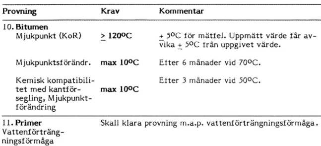
10. Bitumen
Mjukpunkt (KoR)
: lZO°C
+ 5°C för mätfel. Uppmätt värde får
av-Vika : 5°C från uppgivet värde.
Mjukpunktsförändr.
max lO°C
Efter 6 månader vid 70°C.
Kemisk kompatibili-
Efter 3 månader vid SOOC.
tet med kantför-
max lO°C
segling,
Mjukpunkt-förändring
ll. Primer
Skall klara provning m.a.p. vattenförträngningsförmåga.
Vattenf
Pr
ovn
in
g
K r a v K o m m e n t a r12
.
Vl
dh
at
tn
mg
mo
t
*
Be
to
ng
-M
A
B
4T
-Gj
ut
as
fa
lt
-Ka
nt
is
ol
er
in
g
_>_
1.
0
N
/
m
m
2
_>_
0.
5
N/
mm
2
_>_
1.
0
N/
nn
m2
3_
1.
0N
/m
m2
Ef
te
r
ål
dr
in
g:
Dr
ag
kr
af
ts
ök
ni
ng
:
20
0
N/
s
Vär
me
ch
oc
k;
Väg
sa
lt
(1
0
dyg
n)
;
70
°C
,
(2
1
dyg
n)
;
Fr
os
t
-
tö-cyk
le
r
(7
st
)
Dr
ag
yt
an
s
ra
di
e:
25
m
m
Pr
ovn
in
g
vi
d
rum
st
em
pe
ra
tur
.
Ut
läg
gn
.t
em
p.
lB
OO
C.
Br
ot
t
får
ej
up
ps
tå
i
ma
tt
an
.
Ut
läg
gn
.t
em
p.
ZQ
OO
C.
Ef te r vär m e c h o c k IS OO C.13
.
Sk
juvh
ål
lf
as
th
et
(M
AB
4T
,
Gj
ut
as
fa
lt
)
__
0.
15
N/
mm
2
ef
te
r
10
m
m
"g
li
dväg
"
Ef te r 3 m ån a d e r vi d 50 °C .Sk
juvh
as
ti
gh
et
:
10
mm
/m
in
Ar
ea
:
2
x
(1
55
mm
x
11
5m
m)
In
sp
än
ni
ng
st
ryc
k:
0.
07
N/
mm
z.
Pr
ovn
in
g
vi
d
rum
st
em
pe
ra
tur
.
14
.
Sp
ri
ck
öve
rb
ryg
ga
nd
e
för
måg
a
Sp
ri
ck
fr
i
ef
te
r
10
00
pul
se
r.
Vi
d-häf
tn
in
gs
t'
ör
lus
t
<
0.
5
m
m
in
ti
ll
be
to
ng
sp
ri
ck
an
Sp
ri
ck
fr
i
ef
te
r
50
0
pul
se
r
L
ö
so
m
ova
n.
Pr
ovn
in
gs
te
mp
er
at
ur
:
-2
00
C
Am
pl
it
ud
:
0.
2
m
m
(0
.5
-0
.7
)
Fr
ek
ve
ns
:
1.
0
H
z
Ef
te
r
ål
dr
in
g:
V är m e c h o c k ;Väg
sa
lt
(l
O
dyg
n)
;
70
°C
,
21
dyg
n;
Fr
os
t-
tÖ-cyk
le
r
(7
st
)
Tabell 3FLEXIBILITET (böjtest)
Provningsmetoden överensstämmer i huvudsak med böjtest enligt t ex
DIN 52123.Flexibilitet i kyla undersöks på icke åldrat prov och på prov som
värmeåldrats fritt hängande vid 70°C i ventilerat värmeskåp under
6 månader.
Provning utförs i frysrum vid -20°C, -15°C, -lO°C osv ( i steg om
5°C). Provbitar skärs ut i längd- och tvärriktning, 200 mm x 50 mm.
Normalt provas minst 3 provbitar per material och temperatur.
Prov-bitar och böjplatta tempereras till aktuell provningstemperatur under
minst 2 timmar innan provning utförs.
Prov som värmelagrats provas endast i längdriktning.
Vid provning böjs provbiten manuellt, med mattans ovansida liggande
an mot böjplattan. Böjningen utförs med jämn hastighet under 5
se-kunder. Därefter undersöks provet visuellt, varvid förändringar som
sprickor och brott noteras.
Böjplatta med böjradie 15 mm används normalt. Vid "avvikande"
lekar används böjplatta med böjradie ungefär 5 x svetsbitumens
tjock-lek.
Om samtliga provbitar, vid en bestämd temperatur, befinnes sprickfria
anses produkten klara böjprovet vid denna temperatur. Prov med
ensta-ka sprickor (sprickdjup <0,5 mm) godkännes.
EUROPEAN STANDARD
DRAFT
NORME EUROPEENNE
prEN
EUROPAISCHE NORM
UDC
Key words:
English version
BITUHEN SHEETS FOR WATERPROOFING
DETERHINATION OF FLEXIBILITY AT LOW TEHPERATURE
Feuilles d etancheite a base de bitume: Bituaenbahnen für Abdichtungen: . ' . .
Determination du comportement au pliaqe a basse temperature
BeStlmmung des Blegeverheltens bel ledrlgen Temperaturen
This draft European Standard has been drawn up by Technical Committee CEN /TC 2 5 4 lt ts submitted to the CEN members for public enquiry.
lf this draft becomes a European Standard. CEN members are bound to oomply wnh the requnrements of the CEN/CENELEC Common Rules which stipulate the conditions tor giving this European
Standard the status of a national standard without any alteration.
l
This draft European Standard was established by CEN in three officral versions (English, French, German). A version in any other language made by translation under the responsability of a CEN
member into its own language and notified to CEN Central Secretariat has the same status as the
official versions.
CEN members are the national standards organizations ol Austria. Belgium. Denmark, Finland. France, Germany, Greece, lceland. Ireland. haly. Luxemburg, Netherlands, Norway. Portugal, Spain, Sweden. Switzerland and United Kingdom.
'
CEN
European Committee for Standardization
Comifé Europeen de Normalisation
Europaisches Komitee für Normung
Central Secretariat : rue de Stassart 36, 8-1050 Bruxelles
© CEN 1991. Copyright reserved to all CEN members Ref.no. prEN
Page 2
prEN :1992
CEN/TC 254 : SCl : WGZ
WI-6 : Determination of Flex1biliy at Low Temperature
FOREWORD
This European Standard was prepared by the CEN Technical
Committee TC
254
-
SC
l
:
"Bitumen
Sheets"
ftm*
which
the
secretariat is held by Deutsches Institut für Normung (DIN), in
accordance with the SCl scope
preparation of EMropean Standards on factory made
bitumensheets for waterproofinq of building
construction and civil engineering'
The term waterproofing' includes the control or prevention of
water and water vapour movement within the construction.
This Standard is CHMP of a group CM? test methods for the
characterisation and/or Classification (JE bitumen sheets as
manufactured or supplied before use. The methods of test relate
exclusively tx> products, or tx> their components where
appropriate, and not to waterproofing sheeting systems composed of such products and installed in the Works.
This Standard is tc be read in conjunction with EN OOO-O. General
Standard for Bitumen Sheets for Waterproofing.
Requirements arerunagenerally'specified.in this Standard. 'These
will be covered.in EN OOO-O, General Standard, the national rules of usage or design guides as appropriate, or as specified by the designer of the works, as the case may be.
O.
Introduction
The object of the test is to measure the susceptibility of the
bituminous coating of a sheeting to cracking when flexed underspecified conditions at low temperature. The low temperature
flexibility is defined as the lowest temperature at which the
specimen may kx; flexed Mdthout cracking inuknr the specified
conditions. The test result is primarily dependent on the type
of coating and secondarily on the thickness of the sheet, the
type and position of the reinforcing base as well as the
behaviour of the surfacing material. The use of the test results
directly to compare the performance of coatings in sheetings of
different construction is strictly limited because of the
influence of other parameters, which has not been quantified.
Only the results from sheetings having the same construction can be used to compare the performance or quality of the coating.
The test primarily serves to characterise bitumen sheetings. It
can also be used to evaluate how the performance of the coating
changes during artificial ageing. It is not possible to relate
the test results to the actual performance of a product at low temperature in service.
1. Scope
This European Standard
specifies the method of
test for
the
characterisation CM? bitumen sheetings for katerproofing kdth
respect to resistance to cracking on bending at low temperature. The test applies to bitumen sheetings reinforced with non woven
or woven bases made of mineral, synthetic or natural fibres.
It
may also be used for sheetings with other types of reinforcement
or for those without reinforcement.
The test is performed on the top and bottom faces either (i) at
a pre determined temperature or (ii)
successively at different
pre assigned temperature levels to determine the actual
temperaturexat which cracking occurs. The test therefore serves
(1) to confirm that the actual cold bending temperature meets the
minimum requirement for that product,
or (ii) to determine the
specific cold bending temperature for a product, e.g. to measure
the change in this property as a consequence of artificial
\ Page 4
prEN :1992
CEN/TC 254 : SCl : WGZ
WI-6 : Determination of Flexibiliy at Low Temperature
______-__----________-_-___________________.__-___.--__-______-____-2. References
EN 000.0. General Standard for Bitumen Sheets for Waterproofing.
3.
Definitions
Sample
-
Roll of bitumen sheeting from which a
test sample is to be taken;Test Sample - Piececüfsample fromvüüxüispecimens are
to be cut;
Specimens - Test pieces cut from the Test Sample.
For other definitions see IüJ OOO-O General Standard
4. Principle of the Test Method
Specimens taken from test samples are bent through 1800 using a
special apparatus placed in a refrigerated liquid. The test is
performed (nu both faces cüf the sheeting. TNK; specimens are
examined for the presence of cracks in the coating after bending.
5. Test Equipment
The construction and method of operating the test apparatus are
illustrated in fig.1. The apparatus consists of two fixed non
rotating 20mm diameter cylinders with a 30mm diameter moveable
non-rotating cylinder positioned between them. The distance a'
between the two fixed cylinders is adjustable so that the gap
between the fixed cylinders and
the central
cylinder may be
adapted to the thickness of the sheeting to be tested.
The whole apparatus is immersed in a thermostatic bath which can
be controlled to O.1°C in the range +20W: to -40°C.
The cooling
liquid may be a mixture of methanol : water (in the volume ratio
1:1 down to -30W3 and 2:1 down to -40°C) or monopropylene glycol: water (in the volume ratio 45:55 down to -25%U
'.
The measurement of temperature in the bath is made at the level
of the specimen using a separate ninstrument suitable for
Page 5
prEN :1992
CEN/TC 254 : SCl : WGZ
WI-6 : Determination of Flexibiliy at Low Temperature
.______________._______________-_..____________-__.___________-__ _____.
The test is carried out by raising the central fleXing cylinder
at a constant rate of 360mm/min against the underside of the
specimen 5x) that the specimen tis wrapped around it. and bent
through 18WÃ An electronic control system must ensure that the
cylinder moves a constant rate of 36015 mm/min throughout
the
bending process
regardless cü?
test temperature.
Cracks
are
detected by visual inspection without additional optical aids.
For ease of inspection the movement of the flex1ng cylinder lS
arranged so that at the end of the test the specimen protrudes
frtml the surface CM? the cooling liquid. The movement is
restricted by a su1tably positioned stop or limit switch.
(l)
Because methanol is toxic il: should only be used en: low
temperatures (<-20%H. Monopropylepe glycol is not tox1c
and can be used at temperatures >-25C.
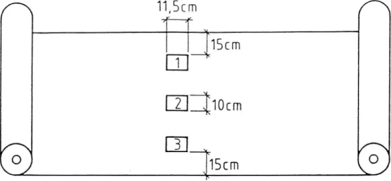
6. Sampling
Specimens are prepared from a test sample taken from the middle
third of the roll of bitumen sheeting. For tests in accordance
with 8.3 below two sets of five specimens, each measuring 140 x
50mm, are cut with the longer dimension in the longitudinal
direction of the roll. The distribution of specimens is such
that five may be cut across the width of the sheeting at regular
invervals with no specimen closer than 150mm to the edge,(see
fig.2). Starting at one side of the sheeting, the specimens are
numbered sequentially and marked in sets of five. The t0p and
bottom faces of the specimens are also identified.
When the object of the test lá; no determine the actual cold
bending temperature a larger number of sets of specimens will be
needed (see 8.4)
7. Preparation of Specimens
Any protective film on the underside of the sheeting must first
be removed. The most convenient way of doing this is to apply
a strip of adhesive tape to the film, cool the sheeting to -lOOC
and then peel the film from the sample using the strip of
adhesive tape.
Removal of the film by means of a gas flame is
not allowed.*__*_-_____-.__-__.____-_____________--________-___________________
The test specimens are conditioned at room temperature (21+/-2°C)
for at least 24 hours before being tested. They are laid on a
flat surface without touching each other and without sticking to
the surface. If necessary a sheet of siliconised paper can be
used to prevent sticking. Loose surface granules are removed by
gentle tapping.
8. Test Procedure
8.1 Preparation of the Test Equipment
Before a series of tests the gap a' between the fixed
cylinders is adjusted so that the space between the flexing
and
fixed
cylinders
is
approximately
the
same
as
the
thickness of the specimen and 5x) that the latter can kx;
pulled between these cylinders without significant
frictional resistance. The apparatus is then placed in the
refrigerated bath so that the fixed cylinders are about
10mm
beneath
the
surface
of
the
liquid.
The
flexing
cylinder is set at its low position.
The test apparatus lS
then cooled to the specified test temperature +/- 1%38.2 Conditioning of the Specimens
After the specified test temperature has been attained
(+/-1W3) the specimens are supported.on za wire mesh and
placed in the refrigerated liquid at the level of the fixed
cylinders. The specimens are kept im] the refrigerated
liquid for at least 30 minutes and not more than two hours. During this time the average test temperature is adjusted
tm>within +/- 0.25%:of the specified test temperature. The
temperature indicated by the temperature probe placed at
the level of the specimen must not vary by more than
+/-O.4%Z at any time.
Once these adjustments have been made the flexibility test is performed in accordance with sections 8.3 or 8.4 and all
specimens must be tested within the maximum two hour
Page 7
prEN :1992
CEN/TC 254 : SCl : WGZ
WI-6 : Determination of Flexibiliy at Low Temperature
_-_---_______-____-_._-_________________.___________._______-______
8.3 Test at a specified Temperature
Two sets of five specimens, one for testing the upper
surface and the other for testing the lower surface of the
sheeting, are conditionad at the specified average test
temperature as described in section 8.2 and then tested as follows
The specimens are placed between the flexing and fixed
cylinders, one after the other, with the side to be tested
uppermost. The 'f1exing cylinder lf; then set ll] motion
pushing upwards against the specimen at a constant speed of
360 +/- 5mm so that the specimens are bent evenly around
it.
The fixed cylinder should stop 30mm above the fixed
cylinders (see fig.l). In this position the surface of the
specimen should protrude from the refrigerating liquid; if
not the level of the liquid must be adjusted.
The surface of the specimen must be examined for cracks
within 5 sec of the completion of the bending operation in
good light using the naked eye, corrected for defective
vision if necessary, but without additional optical aids.
Cracking is noted if a fissure or several partial fissures
in the coating extend as far as the reinforcing base.
All
five specimens in a set are tested one after another. All
five specimens may be tested simultaneously if the
apparatus is large enough to allow thisu
The product passes the test at the specified temperature if
at least four out (ME
five specimensof both sets
ck) not
crack.8.4 Determination of the Actual Cold Bending Temperature
If the actual cold bending temperature of a bitumen
sheeting is to be measured
(eg in order to show changes
caused
by
artificial
weathering)
the
procedure
is
as
follows:A series of exploratory tests on single specimens is
carried out at fixed temperature steps of STL starting at
a _maximum of 0%L in order to determine the highest
temperature at which cracking occurs. The test
temperatures are therefore always multiplies of 6°C
___-____-_____-___________-___-____________-__-_-_____-______*__
Starting at time highest temperature en: which cracking
occurred the actual cold bending temperature is defined
more precisely by conducting tests at intervals of 2%:. A
set of five specimens must be used at each test temperature and. The test is carried out as described in section 8.3. The test temperature is increased in intervals of 2%: until
at least four out of five specimens of a series, tested
together or immediately one after another, do not crack.
This temperature is defined as the cold bending temperature of the sheet and is the result of the test.During this test time specimens nmst be conditioned as
described in section 8.2. The top and bottom sides of the
sheeting must be tested separately.
9. Observations & Data Reduction
9.1 Test at Specified Temperature
The product passes the test if at least four of the five
specimens do not crack when tested at the specified
temperature.
9.2 Determination of Actual Cold Bending Temperature
The temperature limit is the temperature of the step at
which four out cüf five specimens pass.Both sides (ME the
sheeting may have different cold bending temperatutres.
10. Test Report
The test report shall include the following particulars :
(a)
Complete identification of the product tested,
including
type,
source,
manufacturer's
code
number,
product
information and any other pertinent information;
(b) Method of test and corresponding conditions if different
Page 9
prEN :1992
CEN/TC 254 : SCl : WGZ
WI-6 : Determination of Flexibiliy at Low Temperature
(c)
Test result
(1)
pass or fail at the speCified
temperature;both sides oftjnamaterial. (ii) cold bending temperature in °C for top
and bottom faces.
(d) Comment. on type and deptht of :fissures or eVidence of
delamination;
(e)
Comparison.
with
any
specified.:reguirements,
having
due
regard to the precision limitations of the method.11. Precision of Test Method
The test limits refer only to sheetings with polymer modified
coatings.
11.1 Repeatability Conditions
Standard deviation of results : or =
l.2%$
Confidence limits (95%) for single result: gr: : 2.3WZ
Repeatability as the difference between two results r==
3°C
11.2 Reproducibilitv Conditions
Standard deviation of results : or =
2.2W3
Confidence limits (95%) for single result: gr: : 4.4%:
I360nwn/nnn thermocoüple
? _ /
cooling fluid
'73::Ii::::::' 2 0
20 m m
7:::::::::::'-'
F
start Of bending
finish of bending
I
I *WScm
1:a
2::
Bi*
i]
Scm
4::
K/_\\
S[___+7
//_\\
ÄÄ/
15cm
\fä/
middle third of the roll of bitumen sheeting
.4 .á
Fig.2
Sampling
; rr'
VÄRMEBESTÃNDIGHET (avrinning)
Metod:
Provningsmetoden överensstämmer i huvudsak med t ex DIN 52123.
Provningen innebär att provbitar (100 mm X 100 mm) upphänges lodrätt
(i mattans längdriktning) 2 timmar vid 100°C i ventilerat värmeskåp,
varefter de bedöms med avseende på eventuell avrinning, dvs
för-skjutning i täckskikt under värmepåverkan.
Normalt
provas minst 2
provbitar per material.
Enligt kravspecifikationerna i Bronorm 88 får provet efter 2 timmar
vid 100°C inte uppvisa någon avrinning (<0,5 mm).
EUROPEAN STANDARD D R A F T
NORME BUROPEENNE prEN
EUROPÄISCHE NORM . . . . .. 1992
[NBC
Key words
English version
BITUMEN SHEETS FOR WATBRPROOFING DETERMINATION OF FLOW PROPERTIES
AT ELEVATED TEMPERATURE
Feuilles d'etancheite a base de bitume: Bitumenbahnen fur Abdichtungen:
Determination du comportement Bestiimung des Ablaufverhaltens
au fluage a haute temperature bei höheren Temperaturen
This draft European Standard has been drawn up by Technical Committee CEN/TC
254. It is submitted to the CEN members for public enquiry.
If this draft becomes a European Standard, CEN members are bound to comply with the requirements of the CEN/CENELEC Common Rules which stipulate the conditions for giving this European Standard the status of a national standard without any alteration.
This draft European Standard.was established by CEN in three offic1al versions
(English, French, German). A version in any other language made by
translation under the responsibility of a CEN member into its own language and
notified to CEN Central Secretariat has the same status as the offic1al
versions.CEN members are the national standards organizations of Austria, Belgium, Denmark, Finland, France, Germany, Greece, Iceland, Ireland, Italy, Luxemburg, Netherlands, Norway, Portugal, Spain, Sweden, Switzerland and United Kingdom.
C E N
European Committee for Standardization
Comité Européen de Normalisation
Europáisches Komitee für NormungCentral Secretariat : rue de Stassart 36, B-1050 Bruxelles
_.__-___-_._________--___-_______-__-______._
Page 2
pr EN :1992
CEN/TC 254 : SCl : WGZ
WI-7 : Determination of Flow Properties at Elevated Temperature
FOREWORD
This European Standard was prepared by the CEN Technical
Committee ?Ii 254 - SC 1 : "Bitumen Sheets" for which the
secretariat is held by Deutsches Institut Für Normung (DIN), in
accordance with the SCl scope
preparation of European Standards on factory made bitumen
sheets for waterproofing of building construction and civil
engineering'
'
The term waterproofing' includes the control or prevention of
water and water vapour movement within the construction.
This Standard is one of a group of test methods for the
Characterisaticmx
and/or
Classification
(M5 bitumen
sheets
as
manufactured or supplied before use. The methods of test relate
exclusively to products, or to their components where
appropriate, and not to waterproofing sheeting systems composed
of such products and installed in the Works.
This Standard is to be read in conjunction with BN OOO-O, General
Standard for Bitumen Sheets for Waterproofing.
Requirements are not generally specified in this Standard. These
will be covered in BN OOO-O, General Standard, the national rules
of usage or design guides as appropriate, or as specified by the designer of the works, as the case may be.Page 3
pr EN :1992
CEN/TC 254 : SCl : WG2
WI-7 : Determination of Flow Properties at Elevated Temperature ___-_______--___.___.____---_-_-____________._________________________
O. Introduction
The test measures the flow resistance of the coating of a bitumen sheeting over the reinforcing layer when suspended vertically at
elevated temperature. The flow resistance is indicated by the
temperature at which the coating over the reinforcement moves by
2 mm. The test result depends firstly on the type of coating and
secondly on the sheeting thickness, the type and position of the
reinforcing layer as well as the mass and type of mineral
granules on the surface. .A<direct comparison of the test results
yields only limited information about the quality of the coating because the effects of the other parameters cannot be assessed
accurately. However, results on sheetings with the same
composition can be used to compare the quality of the respective coatings.
The test serves primarily to characterize bitumen sheetings. It
may also be used to monitor the changes in properties
accompanying artificial ageing. llzis not possible to relate the
test results with sufficient accuracy to the actual performance
of the product at elevated temperatures.1. Scope
This European Standard describes the method of test for the flow resistance of the coating of bitumen sheetings with non-woven or
woven reinforcement made from ndneral, synthetic (HT natural
fibres when exposed to elevated temperatures. Sheets with other
reinforcements may also be tested using this procedure. 'The test
is carried out both on the top and bottom coatings of the
sheeting either
(i)
at a predetermined temperature,
or
(ii)
successively at various temperature levels in order to determine the actual flow temperature with sufficient accuracy.The test thus serves to (1) confirm the flow temperature claimed
for a ;ntduct,
or
(ii)
identify the actual flow
temperature
specific to the product, e.g. when measuring the change in flow
resistance accompanying
artificial ageing.
In the case of APP bitumen coatings, attention is drawn to the
particular comments in 8.0 and later sections of this standard.
2. References
EN 000-0. General Standard for Bitumen sheetings for
Page 4
pr EN :1992
CEN/TC 254 : SCl : WG2
WI-7 : Determination of Flow Properties at Elevated Temperature
3.
Definitions
Sample
-
Roll of bitumen sheeting from which a
test sample is to be taken;Test Sample
-
Piece of sample from which specimens are
to be cut;Specimens - Test pieces cut from the Test Sample.
For other definitions see EN OOO-O General Standard
4. Principle
Specimens prepared from za test sample of the product are
suspended vertically in an oven heated at a specified
temperature. The displacement of the coating relative to the
reinforcement in the tütumen sheet is measured (nu both faces
after a speCified time. Failure is defined as a mean
displacement greater than 2 mm. The actual temperature of flow
is determined by interpolation of results observed at two test
temperatures.
5. Test Equipment .
The test is performed in forced circulation, unventilated oven.
The maximum temperature difference within the oven spacewmust not
exceed : 1.5°C and the fluctuation during the test at any one
position must not exceed i 0.5%L
A reference specimen with a calibrated thermocouple accurate to
0.1%2 is also required. This reference specimen consists of a
sample measuring 115 >< 100 x
4:rmn (approx)
taken from a
bitumen sheeting and completely wrappad in aluminium foil to
prevent any flow of the coating. The thermocouple is embedded
in the coating of the specimen. The reference specimen is used
to adjust, monitor and control the test temperature.
The
oven
must
have
sufficient
power
so
that
at
every
temperature-level the initial temperature (as measured with the
reference spec1men) can be regained.i11 < 15 minutes after the
Page 5
pr EN :1992
CEN/TC 254 : SCl : WG2
WI-7 : Determination of Flow Properties at Elevated Temperature ____-_-_____.-_____-______.___.__-___-____.__._.______-__-____.___________
Other essential equipment consists of
- a clamp with a minimum width of 100mm to provide continuous
support across width of test specimens and for suspending
these in the test area (see fig.l);
- Optical instrument for measurement of distance readable to
an accuracy of 0.05 mm
- a tool for inserting 4 mm internal diameter pop rivets
-
a template for drawing a marker line (see fig.l) 7
-
white, water resistant indian ink (marking ink) ;
- draughting pen for indian ink to produce continuous line of
0.45mm width;
- an electronic temperature recorder for monitoring the
temperature of the reference specimen;
- Siliconised paper.
6. Sampling
For tests according to 8.2, three test specimens each measuring
115 x 100mm are cut from the middle third of the bitumen sheeting with the larger dimension parallel with the machine direction of
the sheeting. The speCimens are taken eat regular intervals
across the width of the sheeting with the first and last
specimens run:
closer
than
150mm
to
'its
edge,
(see
fig.2).
Starting at one side of the sheeting the specimens are numberedsequentially and marked in sets of 3. The top and bottom faces
are identified. When the zunnuü. flow temperature is 'U3 be
measured the number of sets is increased (see section 8.3)
7. Preparation of Specimens
Any protective film on the underside of the test specimens must
be removed. This can best be effected by applying a strip of
adhesive tape to the film, cooling the specimen to about -lOOC, and then peeling the film from the specimen with the help of the
adhesive tape. The removal of the film by means of a gas flame
is not allowed.
On the narrow side at one end of the test speCimen, the bitumen coating is removed over a 15mm wide strip across the full width
on both faces, to expose the reinforcing base. Two small areas
Page 6
pr BN :1992
CEN/TC 254 : SCl : WG2
WI-7 : Determination of Flow Properties at Elevated Temperature
_-______-__________-_--_______.__.___________-______________-_____-_____
faces of the specimen at the middle of the longer sides (see
detail in figure 1).
This is best done with a heated spatula or
Similar implement, taking care not to damage the reinforcement.
Two 4 mm diameter pop rivets are then punched through the
reinforcement iJi the exposed areas en: the middle cüf the two
longer Sides. Loose mineral granules or other surfacing material
15 removed by gently tapping the specimen. The locating pins of
the marking plate are then inserted into the pop rivets and a marker line 0.45 mm wide is drawn at its scribing edge across the
width and on both faces of the specimen. The marking pen must
be held vertically and the specimen must be laid on a flat
surface whilst the marker line is made.
The test specimens are conditioned län? at least 24 hours at
ambient temperature (21 :t 2 C) on 23 flat surface without
touching each other and without sticking to the surface. A sheet
of Siliconised paper may be used if necessary.
8. Test Procedure
8.1 Adjustment of Test Temperature
The reference specimen is suspended at the centre of the
oven. The mean temperature is then brought to within
*/-0.?? of the intended test temperature. Temperature
fluctuations must not exceed : 1.00C. The temperature is
that recorded by the thermocouple in the reference specimen and is monitored and controlled continuously throughout the
test.
8.2 Testing at a Specified Temperature
Clamps are attached to each of the three test specimens,
prepared in accordance with 7, and forming a series such
that
they
support
the
whole
width
of
the
exposed
reinforcement at the narrow ends. They must not touch or
clamp the coating.
If necessary a separating layer, e.g.
siliconised paper, can be used to facilitate removal of the
clamps after the test.When the reference speCimen has reached the intended test temperature the three test specimens are suspended around
the reference specimen and at the same height, two on one
Slde .and time third CH] the <other, facing' the :reference
specimen. The test specimens should be about 30 mm apart.
Page 7
pr EN :1992
CEN/TC 254 : SCl : WG2
WI-7 : Determination of Flow Properties at Elevated Temperature
.__---___-_______-_________-___________
after placing the test speCimens must not exceed 30 seconds
to avoid excessive changes in the oven temperature. The
specimens zum; kept at tjue test temperature for 120 :t 2
minutes, measured from the moment when the mean test
temperature minus 2°C lf; restored, as indicated hur the
reference speCimen. The temperature must be kept within
the stated tolerances and minor fluctuations must be
corrected as necessary. The test must be aborted in the
event of large fluctuations over extended periods and the test repeated USlng new test specimens.
At the end of the test period of 120 i 2 minutes the test
Specimens are removed from the oven and suspended freely at
ambient temperature for at least four hours. The clamps
are then removed and Ei secomd line 15 marked onto both
Sides of each test speCimen as described in 7.
The extent of the flow is defined as the maXimum distance öL between the corresponding edges of the initial and final marker lines on both faces of each test speCimen, measured
to the nearest 0.1mm using the optical instrument (see fig
1)8.3 Determination of the actual flow temperature
To determine tjua actual flow temperature (exg. fru* the
purposes of monitoring changes as a result of artificial
ageing) the procedure is as follows
An estimate of the temperature corresponding to a flow of
2 mm is made by means of exploratory tests for each face
separately on single specimens over a range of temperature
steps of 5°C. The step temperature is itself to be a
multiple of 5 W: (e.g. 100, 105 110 etc).
The aim is to
find two temperatures, T and T +5°C for which L < 2 mm and
L > 2 mm respectively. The test 15 carried out for single
specimens in accordance with section 8.2 separately for the
two faces. New test speCimens must be used at «each
temperature step.
Having determined the upper and lower temperatures, T+5 and T respectively, the slump in mm 13 determined in accordance with section 8.2 on a set of three specimens for each Slde at the upper temperature (T*5), and a further set of three speCimens for each Side at the lower temperature (T).
The actual slump temperature is determined separately for
each Side of the test speCimen using a linear graph or by
interpolation between the average of both test series to öL