Bachelor thesis
School of Innovation, Computer Science
Design and Engineering. Basic Level 300
2009-09-07
Designing and implementing a small scale Internet
Service Provider
Johan Brown 841213-1636
Alexander Gustafsson Brokås 860901-6913 Supervisor: Gunnar Ågren
Niklas Hurtig 860507-7216 Supervisor: Conny Collander Tobias Johansson 850701-3517 Examiner: Mats Björkman
Abstract
The objective of this thesis is to design and implement a small scale Internet Service Provider (ISP) for the NetCenter sub department at Mälardalen University. The ISP is intended to give NetCenter a network separate from the University’s network, providing them with a more flexible environment for lab purposes. This will give their students an opportunity to experience a larger backbone with Internet accessibility, which has not been previously available. At the same time it will place the teachers in control of the network in the NetCenter lab premises.
The network is designed with a layered approach including an Internet access layer, a larger core segment and a distribution layer with a separated lab network. It also incorporates both a public and a private server network, housing servers running e.g. Windows Active Directory, external DNS services, monitoring tools and logging applications. The Internet access is achieved by peering with SUNET providing a full BGP feed.
This thesis report presents methods, implementations and results involved in successfully creating the NetCenter ISP as both a lab network and an Internet provider with a few inevitable shortcomings; the most prominent being an incomplete Windows Domain setup.
Sammanfattning
NetCenter - en del av Institutionen för Innovation Design och Teknik(IDT) på Mälardalens Högskola, har önskemål om att inneha ett eget nätverk separat från Högskolans för att tillhandahålla en mer flexibel laborationsmiljö till studenterna. Detta är tänkt att ge dem möjligheten till att uppleva och laborera med ett större nätverk som har fullständig Internetåtkomst. Detta har inte varit möjligt innan detta projekt. Målet med detta examensarbete är att designa och implementera en fungerande modell av en Internetleverantör(ISP) för NetCenter. Samtidigt som NetCenter får ett nytt nätverk att laborera med så kommer även lärarna att få full kontroll över nätverket i NetCenters laborationssalar.
För att designa nätet har en strategi för att dela upp nätverket i olika lager använts. Den lageruppdelning som gjorts följer en modifierad modell av Ciscos ”three-layer-strategy” och innehåller ett Internet access lager, ett större core segment och ett distribution lager med ett separat laborations nätverk. Det innehåller både ett publikt och ett privat servernätverk, vilket i sin tur innehåller servrar med bl.a. Windows Active Directory, externa DNS tjänster, övervakningsverktyg och loggning. Internetåtkomst uppnås genom ”peering” med SUNET som tillhandahåller en full BGP ”feed”. Den här rapporten presenterar de metoder, implementeringar och resultat som använts för att framgångsrikt skapa NetCenters ISP; både som ett laborationsnätverk och som en Internetleverantör. Den omnämner även några få oundvikliga brister varav den mest kritiska är en ofullständig installation av Windows Domänen.
ACKNOWLEDGEMENTS
Before you continue reading our thesis report we would like to present a couple of persons to whom we would like to show our gratitude and thank them for the ways they aided us in our thesis work.
We would like to thank:
Our Supervisors Gunnar Ågren and Conny Collander – For aiding us in our thesis work by supporting us and providing us with the equipment we needed. Some took longer time to deliver, but we are glad for the items we actually received.
Joakim Rýden – For some tips along the way and for connecting an external power supply to our equipment.
The Students; Johan Henriksson, Kardo Kaki, Simon Lindgren and Jonas Nilsson – for involvement in design of earlier Internet Service providers models for NetCenter which provided us with a good starting point.
Table of Contents
Terminology...- 9 - List of Figures ...- 12 - 1 Introduction...- 14 - 1.1 Background ...- 14 - 1.1.1 NetCenter ...- 14 - 1.1.2 Equipment ...- 14 - 1.2 Purpose...- 18 - 1.3 Related work ...- 19 - 1.3.1 IP-Hesten...- 19 - 1.4 Problem formulation ...- 19 -1.5 Disposition of the thesis...- 20 -
2 Technologies and Theory...- 21 -
2.1 Operations of an Internet Service Provider...- 21 -
2.1.1 Autonomous Systems...- 21 -
2.1.1.1 Definition and assignment ...- 21 -
2.1.1.2 AS numbers...- 21 -
2.1.2 Network Operations Center ...- 22 -
2.2 Open System Interconnection Reference Model and Transmission Control Protocol/Internet Protocol...- 22 -
2.3 Physical mediums ...- 23 -
2.3.1 Copper cable – Twisted Pair ...- 23 -
2.3.2 Fiber optic ...- 23 -
2.3.2.4 Fiber optical standards ...- 25 -
2.3.3 Media converter ...- 25 -
2.3.4 Synchronous and asynchronous links ...- 26 -
2.4 Addressing and encapsulation...- 26 -
2.4.1 Layer 2 ...- 26 -
2.4.1.1 Ethernet ...- 27 -
2.4.1.2 Point-to-Point Protocol ...- 28 -
2.4.1.3 High-Level Data Link Control...- 29 -
2.4.1.4 Frame Relay ...- 29 -
2.4.1.5 Synchronous Optical Networking/Synchronous Digital Hierarchy...- 30 -
2.4.1.6 Fiber Distributed Data Interface ...- 31 -
2.4.1.7 Spatial Reuse Protocol/Dynamic Packet Transport ...- 31 -
2.4.2 Layer 3 ...- 32 -
2.4.2.1 Internet Protocol...- 32 -
2.4.2.2 Internet Protocol version 6...- 33 -
2.4.2.3 Subnet ...- 34 -
2.4.2.4 Variable Length Subnet mask...- 34 -
2.4.2.5 Classless Inter-domain Routing ...- 34 -
2.5 Routing protocols...- 34 -
2.5.1 Routing Information Protocol ...- 35 -
2.5.1.1 RIPv2 ...- 35 -
2.5.3 Open Shortest Path First ...- 35 -
2.5.4 Intermediate System-to-Intermediate System...- 36 -
2.5.4.1 History...- 36 -
2.5.4.2 Addressing ...- 36 -
2.5.4.3 Domains and areas ...- 37 -
2.5.4.4 Operation...- 37 -
2.5.4.5 Type Length Values...- 38 -
2.5.4.6 IPv6 ...- 38 -
2.5.5 Border Gateway Protocol...- 38 -
2.5.5.1 Operation...- 39 -
2.5.5.2 Multiprotocol BGP...- 40 -
2.5.6 Routing Information Protocol next generation ...- 40 -
2.5.7 OSPF version 3 ...- 40 -
2.5.8 Multiprotocol Label Switching ...- 40 -
2.5.8.1 Labels...- 40 -
2.5.8.2 MPLS Virtual Private Networks...- 41 -
2.5.8.3 Traffic Engineering...- 42 -
2.5.8.4 Any Transport over MPLS...- 43 -
2.5.8.5 IPv6 ...- 43 -
2.6 Network Services ...- 43 -
2.6.1 Domain Name System ...- 43 -
2.6.1.2 Name servers...- 43 -
2.6.1.3 Zones...- 43 -
2.6.2 Terminal Access Controller Access-Control System Plus...- 44 -
2.6.3 Network Time Protocol...- 44 -
2.6.4 Dynamic Host Configuration Protocol ...- 45 -
2.6.5 Simple Network Management Protocol...- 45 -
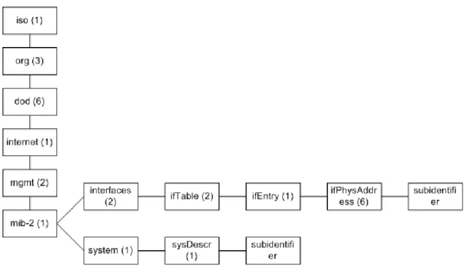
2.6.5.1 Object Identifiers ...- 45 -
2.6.5.2 Operation and versions ...- 46 -
2.6.5.3 Net-SNMP...- 46 -
2.6.6 Network Monitoring ...- 47 -
2.6.7 Dot1x...- 47 -
2.6.8 Trivial File Transfer Protocol ...- 47 -
2.6.9 Netflow ...- 48 -
2.6.10 Secure Shell ...- 48 -
2.6.11 Hot Standby Router Protocol ...- 48 -
2.7 Security ...- 48 - 2.7.1 Encryption...- 49 - 2.7.1.1 Symmetric encryption...- 49 - 2.7.1.2 Asymmetric encryption...- 49 - 2.7.1.3 Combined encryption...- 49 - 2.7.2 Hashing ...- 49 -
2.7.3 VPN tunneling with IPSec ...- 50 -
2.7.4 Public Key Infrastructure...- 52 -
2.7.4.1 X.509...- 52 -
2.7.4.3 Certification Revocation Lists ...- 53 - 2.7.4.4 Certification process ...- 54 - 2.8 Linux ...- 54 - 2.8.1 Linux Distributions ...- 54 - 2.8.1.1 Ubuntu Server ...- 55 - 2.8.1.2 OpenSUSE ...- 55 - 2.8.2 Syslog...- 56 - 2.8.3 Cron...- 56 - 2.8.4 Apache ...- 57 - 2.8.5 RSYNC ...- 57 -
3 Designing and implementing a small scale Internet Service Provider ...- 58 -
3.1 Planning and research ...- 58 -
3.1.1 What is needed? ...- 58 -
3.1.2 A humble beginning...- 59 -
3.1.3 Designing the network topology...- 60 -
3.1.4 Addressing ...- 64 - 3.1.5 Equipment ...- 67 - 3.1.5.1 gw_NetC1 ...- 67 - 3.1.5.2 gw_NetC2 ...- 67 - 3.1.5.3 BIG...- 68 - 3.1.5.4 Small ...- 68 - 3.1.5.5 Upper...- 69 - 3.1.5.6 Middle ...- 69 - 3.1.5.7 Lower ...- 70 - 3.1.5.8 IPH1 ...- 70 - 3.1.5.9 IPH2 ...- 71 - 3.1.5.10 Ambassador...- 71 - 3.1.5.11 SrvSW1 ...- 72 - 3.1.5.12 SrvSW2 ...- 72 - 3.1.5.13 NATROUTER ...- 73 - 3.1.5.14 NOCSwitch ...- 73 - 3.1.5.15 Switch79 ...- 74 - 3.1.5.16 Switch82 ...- 74 -
3.1.6 Open vs. closed source...- 75 -
3.2 Implementation ...- 76 -
3.2.1 Core...- 76 -
3.2.1.1 Design ...- 77 -
3.2.1.2 Networks and addressing ...- 78 -
3.2.1.3 Routing...- 79 -
3.2.2 Servers and Network Operations Center...- 81 -
3.2.2.1 Design ...- 82 -
3.2.2.2 Networks and addressing ...- 83 -
3.2.2.3 Routing...- 84 -
3.2.2.4 Defiant...- 85 -
3.2.2.5 Galaxy ...- 92 -
3.2.2.7 Constitution...- 100 -
3.2.2.8 Excelsior and Sequoia...- 106 -
3.2.2.9 Network Operations Center ...- 109 -
3.2.2.10 Internet access for private networks ...- 109 -
3.2.2.11 Backup solutions: RSYNC ...- 113 -
3.2.4 Lab network (IPH) ...- 113 -
3.2.4.1 Design ...- 114 -
3.2.3.2 Networks and addressing ...- 115 -
3.2.3.3 Routing protocols...- 116 -
3.2.3.4 Labserver...- 120 -
3.2.4 Remote access...- 128 -
3.2.4.1 Networks and addressing ...- 128 -
3.2.4.2 VPN...- 128 -
3.2.4.3 Ambassador...- 132 -
3.2.4.4 Customer Management ...- 135 -
3.2.5 Internet access...- 136 -
3.2.5.1 Design ...- 137 -
3.2.5.2 Networks and addressing ...- 137 -
3.2.5.3 Routing...- 138 -
3.2.5.4 Traffic filtering and security ...- 144 -
3.2.3.5 The gw routers ...- 145 -
3.2.6 Other ...- 145 -
3.2.6.1 Global router configuration...- 145 -
3.2.6.2 The server room ...- 146 -
3.2.6.3 The fiber converters ...- 148 -
3.3 Future work...- 149 -
3.3.1 Proposal 1 - Creating policies and users for Windows AD, 7,5hp ...- 149 -
3.3.2 Proposal 2 - Completing the Windows Server Installation with Microsoft Exchange and a mailbox interface, 15hp ...- 149 -
3.3.3 Proposal 3 – Substituting old equipment, 7,5/15hp ...- 150 -
3.3.4 Proposal 4 – Designing Routines for handling the Network, 7,5hp ...- 150 -
4 Discussion ...- 151 -
4.1 The excessive CPU usage problem on the gw routers ...- 151 -
4.2 Attacks ...- 153 -
4.2.1 SSH brute force...- 153 -
4.2.2 Other ...- 154 -
4.3 The logrotate problem...- 155 -
4.4 Peering with SUNET ...- 155 -
5 Method ...- 156 -
6 Summary and Conclusions ...- 157 -
7 References...- 158 -
7.1 Books and articles ...- 158 -
7.2 Web links ...- 158 -
7.3 Pictures...- 164 -
8 Appendix...- 165 -
8.2 Appendix II – Inventory...- 166 -
8.3 Appendix III – VPN configuration files ...- 169 -
8.4 Appendix IV – The physical topology between the fiber converters ...- 177 -
8.5 Appendix V – Directories for configuration files & applications on the servers- 178 - 8.5.1 Defiant...- 178 -
8.5.2 Galaxy ...- 179 -
8.5.4 Excelsior and Sequoia...- 180 -
8.6 Appendix VI – DNS zones ...- 181 -
8.6.1 nclab.se.zone ...- 181 -
8.6.2 56.238.77.in-addr.arpa.zone...- 181 -
Terminology
3DES - Triple Data Encryption Standard AAA - Authentication, Authorization and Accounting
AC - Alternating Current AD - Active Directory
ADM - Add/Drop Multiplexer
AIP-SSM – Advanced Inspection and Prevention Security Services Module AES - Advanced Encryption Standard AH - Authentication Header
ARP - Address Resolution Protocol AS - Autonomous System
ASA - Adaptive Security Appliance ASDM – Adaptive Security Device Manager
ATM - Asynchronous Transfer Mode AToM - Any Transport over MPLS AXFR - Asynchronous Full Transfer Zone
BGP - Border Gateway Protocol
BIND - Berkeley Internet Name Domain CA - Certificate Authority or
Certification Authority
CDP – Cisco Discovery Protocol
CIDR - Classless Inter-Domain Routing CEF - Cisco Express Forwarding CLI - Command Line Interface CLNS - Connectionless Network Service
CPAN - Comprehensive Perl Archive Network
CRL - Certificate Revocation List CSC-SSM - Content and Security Control Security Services Module CSMA/CD - Carrier Sense Multiple Access/Collision Detection
DC - Direct Current
DES - Data Encryption Standard DH - Diffie-Hellman
DHCP - Dynamic Host Configuration Protocol
DLCI - Data Link Channel Identifier DNS - Domain Name System
dot1x - IEEE 802.1x
DoS - Denial of Service
DPT - Dynamic Packet Transport EAP - Extensible Authentication Protocol
EAPOL - EAP over LAN
EGP - Exterior Gateway Protocol EIGRP - Enhanced Interior Gateway Routing Protocol
ES - End System
ES-IS - End System-to-Intermediate System
ESP - Encapsulating Security Payload FAQ - Frequently Asked Questions FDDI - Fiber Distributed Data Interface FQDN - Fully Qualified Domain Name FTP - File Transfer Protocol
FTP - Foiled Twisted Pair
GBIC - Gigabit Interface Converter GD - Graphics Draw
GRE - Generic Routing Encapsulation HDLC - High-Level Data Link Control HMAC - Hashed Message
Authentication Code
HSRP - Hot Standby Router Protocol HTML - Hypertext Markup Language HTTP - Hypertext Transfer Protocol IANA - Internet Assigned Numbers Authority
ICMP - Internet Control Message Protocol
ICV - Integrity Check Value
IDT - School of Innovation, Design and Engineering
IETF - Internet Engineering Taskforce IGP - Interior Gateway Protocol IKE - Internet Key Exchange
IOS - Internetwork Operating System IP - Internet Protocol
IPCP - Internet Protocol Control Protocol
IPS - Intelligent Protection Switching IPSec - IP Security
IPX - Internetwork Packet Exchange IS - Intermediate System
IS-IS - Intermediate System-to-Intermediate System
ISAKMP - Internet Security Association and Key Management Protocol
ISO - International Organization for Standardization
ISP - Internet Service Provider IXFR - Incremental Zone Transfer LADOK - Lokalt Adb-baserat Dokumentationssystem
LAN - Local Area Network LC - Lucent Connector LCP - Link Control Protocol LDP - Label Distribution Protocol LED - Light-Emitting Diode
LFIB - Label Forwarding Information Base
LIB - Label Information Base LLC - Logical Link Control LSP - Label Switched Path LSP - Link-State Packet LSR - Label Switch Router MAC - Media Access Control MD5 - Message Digest 5
MED - Multi-Exit Discriminator MIB - Management Information Base MIC - Media Interface Connector MM - Multi Mode
MP-BGP - Multiprotocol BGP
MPLS - Multiprotocol Label Switching MRTG - Multi Router Traffic Grapher MTU - Maximum Transmission Unit NAP - Network Access Protection NAT - Network Address Translation NET - Network Entity Title
NLRI - Network Layer Reachability Information
NOC - Network Operations Center NPS - Network Policy Server
NRPE - Nagios Remote Plugin Executor NSAP - Network Service Access Point NTP - Network Time Protocol
OC - Optical Carrier
OCSP - Online Certificate Status Protocol
OID - Object Identifier
OS - Operating System
OSI - Open System Interconnection OSPF - Open Shortest Path First PAT - Port Address Translation PCALC - Path Calculation
PHP - PHP: Hypertext Preprocessor PKI - Public Key Infrastructure PNG - Portable Network Graphics POH - Payload Overhead
POP3 - Post Office Protocol 3 POS - Packet over SONET PPC - Power PC
PPP - Point-to-Point Protocol PSU - Power Supply
RADIUS - Remote Authentication Dial In User Service
RFC - Request for Comments RIB - Routing Information Base RIP - Routing Information Protocol RIPE NCC - Réseaux IP Européens, Network Coordination Center
RIPng - Routing Information Protocol next generation
RIR - Regional Internet Registry RRD - Round Robin Database RSA - Rivest Shamir Adleman
RSVP - Resource Reservation Protocol SA - Security Association
SC – Standard Connector
SDH - Synchronous Digital Hierarchy SDM - Security Device Manager SFP - Small Form-factor Pluggable SHA - Secure Hash Algorithm SHV - Security Health Validator SM - Single Mode
SMS - Short Message Service
SMTP - Simple Mail Transfer Protocol SNMP - Simple Network Management Protocol
SONET - Synchronous optical networking
SPOF - Single Point of Failure ST - Straight Tip
STM-N - Synchronous Transport Module level N
STS-N - Synchronous Transport Signal level N
SUNET - Swedish University Computer Network
SPE - Synchronous Payload Envelope SPF - Shortest Path First
SRP - Spatial Ring Protocol SRR - Single Ring Recovery SSH - Secure Shell
SSL - Secure Socket Layer TACACS+ - Terminal Access
Controller Access-Control System Plus TCP - Transmission Control Protocol TE - Traffic Engineering
TFTP - Trivial File Transfer Protocol TLD - Top-Level Domain
TLV - Type Length Value TOH - Transport Overhead TTL - Time to Live
UDP - User Datagram Protocol UPS - Uninterruptible Power Supply UTP - Unshielded Twisted Pair VC - Virtual Circuit
VCSEL - Vertical-Cavity Surface-Emitting Lasers
VLAN - Virtual Local Area Network VLSM - Variable-Length Subnet Masking
VPN - Virtual Private Network WAN - Wide Area Network YAST - Yet Another Setup Tool
List of Figures
Fig.# Description p.
1.1 The lab premises overview 15
1.2 Network equipment in the lab premises 15 1.3 10720 Router 16 1.4 GSR 12016 16 1.5 GSR 12008 16 1.6 7507 17 1.7 7505 17 1.8 5509 17 1.9 4006 18 1.10 HP 2626 and Cisco 2600 18
2.1 Image of a Standard Connector 25
2.2 Image of a Lucent Connector 25
2.3 Basic MPLS operation 41
2.4 MPLS VPN labels 42
2.5 The hierarchical structure of sysDescr and ifPhysAddress 46
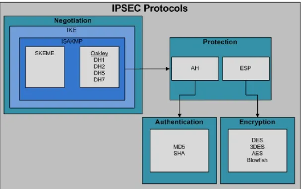
2.6 IPSec protocol suite 51
2.7 Timeline for Debian based Distributions 55 3.1 Topology from ”ISP Stor & Liten” 59
3.2 Internet backbone 60
3.3 FDDI triangle with Cisco 7507 routers 61 3.4 IPH and the Lab premises 61
3.5 The router setup 62
3.6 The original logical topology 62
3.7 The current logical topology 63
3.8 Without an extended core 64
3.9 gw_NetC1 67 3.10 gw_NetC2 67 3.11 BIG 68 3.12 Small 68 3.13 Upper 69 3.14 Middle 69 3.15 Lower 70 3.16 IPH1 70 3.17 IPH2 71 3.18 Ambassador 71 3.19 SrvSW1 72 3.20 SrvSW2 72 3.21 NATROUTER 73 3.22 HP ProCurve 73 3.23 Switch79 74 3.24 Switch82 74
3.26 The logical Core layer 76 3.27 The SRP ring physical topology with names of fiber patch panels 77
3.28 The logical Servers and NOC layer 81
3.29 Overview of the Servers and NOC layer 82
3.30 The event part of run.sh 89
3.31 The account part of run.sh 90
3.32 Screenshot of the web-based interface on Defiant 91
3.33 Screenshot of Nagios status details 96
3.34 Screenshot of the Nagios status map of the network 97 3.35 Screenshot of a MRTG graph displaying bandwidth usage 97 3.36 Screenshots of the roles and features on Constitution 101 3.37 Screenshot of the management page at loopia.se 107
3.38 Traffic flow in the NAT process 112
3.39 The logical Lab Network layer 113
3.40 Screenshot of the IPH lab server index page 121
3.41 Screenshot of the IPH lab configurator 122
3.42 Lab configurator function 123
3.43 Screenshot of the MLRG page 124
3.44 Screenshot of the SNMP test page 125
3.45 Flow chart of autoconf.sh 126
3.46 Logical Remote Access layer 128
3.47 Remote access lab test topology 129
3.48 Remote access lab test topology #2 131
3.49 The logical Internet Access layer 136
3.50 The server room 147
3.51 Screenshot of a Cacti graph showing dropped SNMP packet 151 3.52 Screenshot of a Cacti graph showing CPU usage on GW1 153
1 Introduction
1.1 Background
1.1.1 NetCenterMälardalen University, located in the cities Västerås and Eskilstuna, is one of the largest universities in Sweden and mainly focuses on giving job-related courses so that students will be ready for a career in their area of study. Last year the University underwent reorganization of programs and re-divided them across different schools. Before the change they where divided into smaller divisions called departments. We, the authors of this paper, are students studying at the School of Innovation, Design and Engineering (IDT), previously Department of Computer Science and Electronics (IDE) [MDHIDT]. Mälardalen University was the first place in Sweden that was made a regional Cisco Networking Academy [NETSP], meaning that students there could be enrolled in Cisco’s classes and get help from the instructors on their way to becoming Cisco Certified Network Associates (CCNA). 10 years ago, NetCenter was started as a project at Malardalen University’s IT department and is now a subdivision of IDE (now IDT) which handle all the Universities courses and programs related to Network technology and communications [MDHNETC].
NetCenter is run by a handful of teachers that give lectures, tutor students in both hands-on labs and simulated labs and also offer courses for staff at local companies.
The interest for courses in this area of study has been booming the last couple of years and has led to larger classes for NetCenter to care about. This has been stressful for the premises and equipment available for the students to practice with. The problem has been somewhat mitigated by using lab simulators and an implementation of Cisco’s NETlab. 1.1.2 Equipment
In this section the equipment the students have access to in the lab premises and the equipment that is at our disposal will be presented.
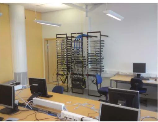
At the lab premises in Mälardalen University there are two rooms with 10 computer stations each, all including wall jacks on top of the desk to alleviate connection of network and console cables to rack of networking devices in the room.
Figure 1.1 The lab premises overview
In the rack there is a variety of Cisco 2600/2800series routers, Cisco Catalyst 3560/3550/2950series switches and a couple of Cisco ASA/PIX Firewalls.
Of course, students also have access to compatible cable types to use with the equipment; console cables, twisted pair cables, DB60 serial connectors and smart serial connectors. The serial cables can be used to simulate a wan-link, but today there is no network to simulate an internet cloud.
The equipment that we are provided with in this thesis work is:
Amount. Model and description Photo
2 Cisco 10720 Router
Figure 1.3 10720 Router
1 Cisco Gigabit Switch Router(GSR) 12016
Figure 1.4 GSR 12016
1 Cisco Gigabit Switch Router(GSR) 12008
3 Cisco 7507 Router
Figure 1.6 7507
2 Cisco 7505 Router
Figure 1.7 7505
1 Cisco Catalyst 5509 Switch
2 Cisco Catalyst 4006 Switch
Figure 1.9 4006
1 HP ProCurve Switch 2626
1 Cisco 2600 Router
Figure 1.10 HP 2626 and Cisco 2600
For more specific information about the hardware available please refer to Appendix II: “Inventory”.
1.2 Purpose
NetCenter intends to create a network and use it as a platform to connect and pair Cisco academies through Mälardalen University. The Network's purpose is to provide IDT the opportunity to offer more realistic case studies of its affiliated computer communication courses in form of laboratory and project assignments in which students get a chance to collaborate with students at other schools in larger project teams, thus needing to use less equipment at the NetCenter lab premises. The network to be created will achieve this by acting as an intermediary station for remote connections, which will give IDT’s students
a chance to experiment with real WAN-networks. This network is intended to function as a private ISP to create neighbor relationships to other academies and there will also be a need to device a plan on how to monitor and provide maintained network operability.
1.3 Related work
This section contains previous projects relevant to ours. There are other projects that resemble ours at other universities, for example www.dnlab.se, but we have not been able to find any concrete information about them.
1.3.1 IP-Hesten
In 2007 another group of students; Johan Henriksson, Kardo Kaki, Simon Lindgren and Jonas Nilsson, at NetCenter implemented a network in a project course which goal was to resemble an actual ISP, so that other project groups could attach several logical sites to it, but not be available for public access [IPHEST]. At the time the group only had access to the three Cisco 7500 Routers and the Cisco 12000 GSRs but the later couldn’t be used without an external power supply unit (PSU). The work however was very successful and paved the way for further growth.
In 2008 the work continued as Jonas Nilsson and Kardo Kaki was assigned a thesis work to develop a network to act as a real ISP, built as a transit-network and offering Internet-connections with public IP addresses [ISPSOL]. They planned to use the old IPHesten as a customer connection to their network. Unfortunately, they still couldn’t get a hold of connections to another, public ISP to peer with. Even though their work wasn’t completed, it provided a lot of information on how to continue the project as it now is our turn to rebuild it anew.
1.4 Problem formulation
The assignment is to design an ISP network to optimally utilize the equipment that is already present and suggest ordering of new equipment if necessary. There is also a demand for designing a Network Operations Central (NOC), to reside in an office space for administration and monitoring the ISP-network. Due to the nature of this project, a lot of time will be used to move, setup and configure devices.
As described in the purpose section, the network will be used for students at the NetCenter lab premises and other academies to interconnect with each other. A way to handle these connections is needed and preferably secured by encrypting the traffic. It is also imperative that the origin of the traffic can be recognized inside our network so that two other academies can be connected on demand. Also, unwelcome traffic should be recognized so that it can be blocked.
The main tasks are to determine how to:
• Setup a network at the local site, so that it acts as an ISP that can peer with other ISPs.
• Create both a practical and secure environment for student lab exercises across the network.
• Manage the network.
Please refer to Appendix I: ”NetCenter specifications and demands”, which is the only written instructions we have received in which NetCenter describes what they want the thesis work to include. As you may notice, this section also made notice of some demands that have been brought up orally during the thesis work.
1.5 Disposition of the thesis
This thesis report is constructed with four main sections, the introduction, a part explaining the background theory of the important technologies that we have or decided not to use. These are followed by an immense section explaining the methods we have chosen to use when implementing all technologies into the network and at the end there is a section in which we discuss problems and solutions that arose during the thesis work. The Technologies and Theory section is subdivided with help of the OSI reference model segmenting it into separate chapters for the three lower OSI layers and in addition a chapter for the remaining layers.
The designing and implementation section is on the other hand based on the approach we used when designing the network topology, dividing it into chapters, each based on the functions that are present in a specific hierarchical network design layer. The model we used for the hierarchical design is presented in the first chapter of the design and implementation section.
To aid the reader there is also a table of contents in the beginning of the thesis quickly followed by a Terminology section hopefully explaining all relevant abbreviation that have been used when writing this thesis. Since the network industry adopted so many different technologies with lengthy and complex names it is very common that they are accompanied by an abbreviation that rapidly is accepted as the de facto alias for the technology.
2 Technologies and Theory
This section will present some relevant technologies and philosophies which is used in the implementation section of this thesis.
2.1 Operations of an Internet Service Provider
An Internet Service Provider (ISP) is an organization that provides other organizations Internet access and network support. ISPs connect to each other and form the Internet. 2.1.1 Autonomous Systems
Autonomous System (AS) is a central concept in computer networking and very important for Internet operation. In effect, an organization must have a unique AS number to be a part of the Internet and connect to other ASs.
AS numbers are handled by the Internet Assigned Numbers Authority (IANA), that assigns blocks of AS numbers to the Regional Internet Registries (RIRs), which in turn assign them to customers. Réseaux IP Européens, Network Coordination Center (RIPE NCC) is the RIR for the Europe region.
2.1.1.1 Definition and assignment
RFC 1771, "BGP-4", stated: "The classic definition of an Autonomous System is a set of
routers under a single technical administration, using an interior gateway protocol and common metrics to route packets within the AS, and using an exterior gateway protocol to route packets to other ASs.", a sufficient definition for an organization [RFC1771]. As
the Internet grew however, a stricter definition for distribution of AS numbers was needed.
RFC 1930, "Guidelines for creation, selection, and registration of an Autonomous System
(AS)", presents some guidelines for when a public AS number should be used. It
establishes that "Without exception, an AS must have only one routing policy." which means an organization can be assigned several ASs if necessary. It also sets some criteria for when a public AS should be assigned and when a private one is enough. Essentially, a public AS is only needed when the AS is multi-homed (connected to several other ASs) and has a separate routing policy from its service provider [RFC1930].
2.1.1.2 AS numbers
The dominant representation of ASs is a 16-bit integer, allowing for 65535 unique ASs. Of these, 64512 through 65535 are defined as private and may not be routed on the Internet [RFC1930]. However, these AS numbers were estimated to be depleted in October 2011, which called for a new AS numbering system [ASNR16].
In RFC 4893 new extensions to BGP was presented that extended the AS number representation to a 32-bit integer [RFC4893]. From January 2007, these new 32-bit addresses are being assigned by IANA extending the AS range to over 4 billion. These addresses use a new dotted format defined in RFC 5396, with the lowest and highest 16 bits written as integers separated by a dot. The 16-bit address 12075 becomes 0.12075 and the new AS number 154000 becomes 2.22928 [RFC5396].
2.1.2 Network Operations Center
An ISP network can be very large with numerous servers and network devices so an information node which gathers data from the entire network is indispensable. That is why every ISP needs a Network Operations Center (NOC). Normally it is a room or department with terminals which display real-time information of the network and monitors the network for failures and alarms. Access to the servers and network devices to configure them are also granted from the NOC.
2.2 Open System Interconnection Reference Model and
Transmission Control Protocol/Internet Protocol
The Open System Interconnection Reference Model (OSI model) is a seven layered model to describe how different protocols and standards communicate with each other and how communication between two nodes utilizes the layer functionality. The OSI model is developed by the International Organization for Standardization (ISO) and is used to simplify the development of protocols and techniques in terms of function and interoperability. A change in one layer should not affect the other layers. The OSI model also simplifies network technology education and understanding. The seven layers of the OSI model are:
• Physical • Data Link • Network • Transport • Session • Presentation • Application
The physical layer or layer one describes how the signals should be transmitted, in which medium and at what voltage when it comes to electrical signals. It also defines what cables and connectors to use in a specific standard. The Data Link layer determines access methods for nodes on a network. It also encapsulates data from the layer above in frames which include a physical address to a node for correct delivery of the frame. Other areas of layer two protocols are flow control and error notifications. The network layer or layer three is where the network address is implemented. Usually in the form of an IP address it functions as the pointer to where the data packets should be sent. Network layer protocols also determine the best path to the destination. The Transport layer incorporates different protocols to make the transmission of layer three packets flow as smoothly and fast as possible. Transport Control Protocol (TCP) which is a common layer four protocol establishes an end-to-end connection with the destination to control the flow of data between the nodes. The session layer controls communication between applications and manages and terminates sessions between them. The Presentation layer is responsible for the correct presentation of data to the application. It includes encoding and decoding techniques. The application layer is the layer closest to the user interface. All the different
types of protocols used in networking applications are application layer protocols, for example HTTP, FTP, SMTP [CSCNF3].
2.3 Physical mediums
In the OSI model the first layer defines what types of physical connections to use in the network and how the signals are sent. There are three types of transmission mediums: electrical, optical and wireless. The most commonly used medium in a LAN is the twisted pair cable used with the Ethernet standard, which send and receive data using electrical signals. The optical transmission which uses light or laser to communicate travels along a fiber optic cable. Fiber optic cables are often used in long distance connections but can also be used in LANs for higher bandwidth than twisted pair cables. Wireless communication is in the form of radio waves. There are numerous layer one standards for transmitting signals including Ethernet, 802.11a/b/g/n, Frame Relay and SONET.
2.3.1 Copper cable – Twisted Pair
Twisted Pair electrical cables are the most common cable for the Ethernet standard. Ethernet has a speed of 10 Mb/s, Fast Ethernet 100 Mb/s Full-Duplex and Gigabit Ethernet 1 Gb/s. There is even a 10 Gigabit Ethernet standard with a speed of 10 Gb/s and also 100 Gb/s Ethernet in development. There are three kinds of twisted pair cables called FTP, UTP and STP. FTP stands for Foiled Twisted Pair and is together with Shielded Twisted Pair (STP) the two types of twisted pair cables that can protect the signal from electronic interference from other bundling cables or from another pair of wires. Unshielded Twisted Pair (UTP) cables have no shielding and can be exposed to electrical interference when the cables are bundled together [WIKITP].
2.3.2 Fiber optic
The use of fiber optics is more widely spread in the ISPs and corporate networks than in private networks. Optical fibers have lower attenuation of the signal than electrical cables and thus it is more suitable for long distance links. Data can be transmitted in two types of modes: single and multi mode. There are a few differences and the networking devices must support the mode of choice. The two modes cannot communicate directly with each other. Long fiber cables are made of glass because of the relatively low attenuation of the signal where as short fiber cables are made of plastic or a combination of the two. Fiber optic cables also have other advantages over electrical cables. The risk of overhearing when bundling cables is nonexistent. The risk of damages in case of thunder is decreased and it is much more difficult to tap a fiber cable than an electrical cable. A fiber optic cable consists of a glass or plastic fiber core and is surrounded by a section of cladding and the outmost section is the jacket [WIKIOF].
2.3.2.1 Single Mode
When data is transmitted in Single Mode a single light pulse is emitted. The light pulse is often emitted in multiple wavelengths. Single Mode fiber cables are relatively cheaper to Multi Mode per meter but the equipment that supports Single Mode is more expensive. Single Mode is most commonly used in long distance fiber optic cables where Multi Mode transmissions are impossible due to the higher attenuation of the light pulse. Single
Mode fiber cables have the same set of connectors as the Multi Mode cables. The Single Mode cables have a core size of between 8 and 10 µm and a cladding diameter of 125 µm. The color of the jacket is yellow. Single Mode fibers support speeds up to 40 Gb/s and with the speed of 10 Gb/s the maximum link distance is 60 km. The marking on the jacket is SM (8-10)/125µm [WIKISM].
2.3.2.2 Multi Mode
In Multi Mode transmissions the signal is divided into multiple light pulses and is emitted into the fiber in an angle to accomplish total reflection. Multi Mode fiber optic cables are preferable in short distance links, such as in an office complex or similar premises. Multi Mode fiber optic cables have a larger core size than Single Mode fibers which enables the multiple light pulses to traverse the cable. The large core size also makes it possible to use simpler electronics on the sending and receiving side such as light-emitting diodes (LEDs) or vertical-cavity surface-emitting lasers (VCSEL). This reduces cost in the Multi Mode networking equipment. Because of modal dispersion the bandwidth is lower than in Single Mode fibers. There are different types of Multi Mode fibers classified in the ISO 11801 standard based on bandwidth named OM1, OM2 and OM3. The OM1 Multi Mode fiber have a core size of 62.5 µm and a cladding diameter of 125 µm and is determined by the grey color of the cable jacket and is named MM 62.5/125µm. The OM2 is named MM 50/125µm, is orange in color and OM3 is named MM 50/125µm and is aqua-colored. OM1 and OM2 support speeds ranging from 10 Mb/s Ethernet to Gigabit Ethernet. OM3 is a laser-optimized multi mode fiber using 850 nm VCSELs and support speeds up to 10 Gigabit Ethernet to a distance of up to 550 m [WIKIMM].
2.3.2.3 Fiber optical connectors
A fiber optical connector connects an endpoint of a Single Mode or Multi Mode fiber to a networking device such as a fiber media converter. The connectors are of various types and sizes. There is no single standard for cable-specific connectors. Fiber optic cables can be terminated with a number of different connectors. Common connectors in network technology fiber optics are:
MIC – Media Interface Connector LC – Lucent Connector
SC – Standard Connector ST – Straight Tip
MIC is a connector for FDDI rings but other connectors can be used also. LC is a connector for SONET and SRP topologies. SC is a very common connector in fiber optic topologies. ST is a connector mainly for multi mode connections. [WIKIOFC]
Figure 2.1 Image of a Standard Connector Figure 2.2 Image of a Lucent Connector
2.3.2.4 Fiber optical standards
There are a number of different gigabit standards for fiber optic communication which aren’t compatible with each other. The standards are defined in the IEEE 802.3z standard also known as 1000BASE-X.
• 1000BASE-SX is communication over a multi mode fiber up to a distance of 550 meters. The light pulse is transmitted at a wavelength of 770 to 860 nm.
• 1000BASE-LX transmits laser at a wavelength of 1270 to 1355 nm over a multi mode fiber up to a distance of 550 m. It can also be used with single mode fibers and can send data up to a distance of 5 km.
• 1000BASE-LH is a modification of 1000BASE-LX with higher quality optics and a wavelength of about 1300 nm and reaches up to 10 km. It is not an actual standard but is a used term in the industry. 1000BASE-LH is backwards compatible with 1000BASE-LX.
• 1000BASE-ZX is not a standard but an industry accepted term and uses wavelengths of 1550 nm and can reach a distance of 70 km using a single mode fiber.
• 1000BASE-LX/BX10 uses different wavelengths of the upstream and the downstream transmissions over a single mode fiber. The standard uses wavelengths of 1490 and 1310 nm for the two streams [WIKIGE].
2.3.3 Media converter
A media converter enables to switch layer one medium in a network link, for example from copper cables to fiber optic cables. The media converter can be a small stand alone device or a slot card in various types of networking equipment. It can also switch duplex and bandwidth rates. There are a vast variety of devices ranging from simple converters to complex systems involving SNMP. In the case of a fiber media converter the most common use is to convert a fiber optic link to a twisted pair interface for input in a switch or router [WIKIFMC].
2.3.4 Synchronous and asynchronous links
These are two types of serial link states. A synchronous link means that the line rate (baud rate) must be specified at the sending and the receiving side either manually or by clock synchronization. On a synchronous link the rate is specified with a clock in which the sending side transmits data and the receiver should read bits on the line. A typical line rate on a serial link is 9600 bits per second. That is the rate in which a transition between a high or low voltage should be sensed on the receiving side. If the clock on one side is different from the other the receiving side can sample the line when the voltage is high or low and thus miss the change in voltage that a correct set line rate should sense. It is when the voltage transitions from a high value to a low or the other way around that the receiving side interprets that as a 0. Constantly high voltage with no transition is interpreted as a 1. On an asynchronous line the sending side has a different clock rate than the receiving and only transmits on the link when sending data. To enable the receiving side to synch the sample rate to the line rate a frame flag must be sent before every frame. It can be a specific combination of 1s and 0s of variable length depending on which line protocol is in use [VR1].
2.4 Addressing and encapsulation
The OSI model defines how data is formatted step by step to prepare it for the actual network transmission. The two layers that add addresses to the data are the data link layer and the network layer.
One of the most fundamental ideas involved in network communication is addressing, without addresses network transmissions wouldn’t work especially well in networks with more than two nodes since there would be no way to for a packet to find it’s destination. The network layer adds globally identifying source and destination addresses before passing it down to the data link layer. These addresses can be used to route traffic to other networks. There are a couple of different kinds of addresses that can be added to the network frame. Which kind of address to be added, is defined by the network protocol that is in use. The most common protocol by far is the Internet Protocol (IP) which adds IP addresses for source and destination nodes.
The data link layer describes how the last step in the packaging process should be performed by incorporating data link layer protocols. These protocols, or encapsulation methods, all use different strategies to packet the data, but the one thing they all have in common are that they add address fields to the packet header. The address at the data link layer describes the actual physical connector of an interface or a computer’s Network Interface Card (NIC). Data link layer addresses are used to find network nodes on the common network.
2.4.1 Layer 2
The second layer in the OSI-model defines how the data is sent and also to which node. Therefore an addressing protocol must be in place. For serial link with only two nodes PPP and HDLC are common protocols. For multi-noded topologies Ethernet with its MAC and LLC protocols are common. Layer two protocols are also responsible for solving frame collisions when two nodes are sending data simultaneously. Layer two
protocols addressing scheme are of a flat structure unlike IP addresses. This means no part of the address reveals where it belongs or what its source is. In the case of Ethernet this corresponds to the MAC-address on the interface [WIKIDLL].
2.4.1.1 Ethernet
Ethernet over twisted pair is the most common standard for local area network designs. It includes both which physical devices and cables to use and addressing schemes for data delivery. It incorporates the first two layers in the OSI-model. Ethernet is most commonly used together with the TCP/IP stack for a complete network connection between various devices. Ethernet is a star-topology network. The sub network consists of several nodes interconnected by the use of hubs, repeaters, bridges and switches. Routers deliver data based on layer three addresses like an IP-address to the specific sub network the destination resides on and the router knows to which MAC-address the IP packet should be sent based on its ARP-table. It can be directly to the destination node or to a switch for further processing [WIKIET].
2.4.1.1.1 Media Access Control
Media Access Control (MAC) protocol is a sub layer of the Data Link layer in the OSI-model. The protocol allows access for several nodes on a shared physical medium like bus networks, ring networks like SONET and hub networks like Ethernet. It is responsible for framing data packets that arrive before transmitting them on the sub network. Every physical interface that connects to a network has a MAC-address. MAC has a hexadecimal 48-bit addressing scheme in a flat structure. MAC-addresses does not need to be unique in the entire internetwork but only on the local sub network since other protocols are responsible for delivering data on the internetwork like the Internet Protocol [WIKIMAC].
2.4.1.1.2 Logical Link Control
Logical Link Control (LLC) is a sub layer of the Data link layer in the OSI-model and acts as an interface between Layer three protocols like IP and the MAC-protocol. It allows several layer three protocols to access the same shared physical medium through multiplexing and flow control. It also demuxes the received signal containing various layer three protocols. LLC communicates between the MAC-layer and the layer three protocol based on the information in the Ethertype field in the Ethernet frame [WIKILLC][WIKIMP].
2.4.1.1.3 Ethernet frame
Before transmitting the data on the network an Ethernet framing must be done. The data or payload is encapsulated with a header and footer. The header consists of a preamble, MAC-source and MAC-destination. A field in the header called Ethertype defines which layer three protocol in the payload that is encapsulated. There can also be a field containing the dot1q-tag present in the header. The footer consists of a checksum of the entire frame in the form of a four byte CRC32 value. The standard maximum size of the payload can be 1500 bytes and is called Maximum Transmission Unit (MTU) and for the entire frame the size adds up to 1526 bytes. The least significant bit is transmitted first in a byte [WIKIET].
2.4.1.1.4 Collisions
In a multi-node network collisions can occur when two or more nodes send data simultaneously. To avoid collisions in a hubbed network a method called Carrier Sense Multiple Access/Collision Detection (CSMA/CD) was implemented in the Ethernet standard. Before sending data on the link the sending interface listens on the line (carrier) if any node is sending at that time. If the line is free the interface sends the frame. If the line is busy, the interface waits with its transmission until the line is free. If the interface is sending a frame and a collision is detected, meaning another node is transmitting at the same time, the transmitting nodes send a jam signal on the line and waits for a random period of time before trying to send again. With the implementation of full-duplex switches in Ethernet networks the need for CSMA/CD was virtually gone since transmit and receive are carried out on different wires and a switch limits the collision domain to only the sending and receiving node [WIKICC].
2.4.1.2 Point-to-Point Protocol
Point-to-Point Protocol (PPP) is a protocol for communication between two nodes on many types of physical networks including serial links, PSTN and SONET. It supersedes HDLC and is designed from that protocol. PPP can have various types of addressing-protocols to locate the destination. IP, IPX and AppleTalk are examples of addressing-protocols that PPP can be used with. PPP is a synchronous and asynchronous protocol with numerous features that include password protection, encryption, compression and auto negotiation between nodes. The PPP frame consists of a flag, address, control, protocol, information, padding and checksum fields. The information field has a maximum size (MTU) of 1500 bytes. There are a number of other protocols in use when PPP establishes a connection. Link Control Protocol (LCP) auto negotiates with the two nodes to set parameters such as datagram size, escape characters and authentication. A basic PPP link must be established first for LCP to start communicating. A Network Control Protocol for the various addressing-protocols must run atop PPP. For IP the protocol is called Internet Protocol Control Protocol (IPCP) for version 4 of IP and for IPv6 IPv6CP. For IPX it is called IPXCP and for AppleTalk ATCP. PPP is a bit-oriented protocol [WIKIPPP].
PPP has five states that a link can be in:
Link Dead – This is the phase in which the link is down due to user disconnect or link failure.
Link Establishment phase – LCP negotiation initiates. If successful the following two states can occur.
Authentication phase – An optional phase for password authentication.
Network-layer protocol phase – The layer three protocol for addressing is invoked. In the case of IP the IPCP is used to establish connection.
Link termination phase – The link is terminated either by authentication failure or by repeated checksum errors or by user disconnect.
2.4.1.3 High-Level Data Link Control
High-Level Data Link Control (HDLC) is a bit-oriented communications protocol for serial links and ring topologies. Bit-oriented means that the transmission is a series of bits and is not interpreted as characters and symbols but as a stream of 1s and 0s by the HDLC protocol. HDLC can therefore deliver any data frame regardless of its content. It can send frames on both synchronous and asynchronous links. In the case of an asynchronous link when the baud rate is unknown for the destination node a frame delimiter or flag must be sent first before the frame is transmitted. The HDLC flag is the bit value “01111110”. If more than five 1s is present in a row inside the payload bit stuffing must occur otherwise the receiving side believes that the frame has ended because of the occurrence of six 1s in a row, which corresponds to the HDLC flag. Bit stuffing means that a 0 is inserted after every occurrence of five 1s inside the payload. This 0 is removed at the receiving side. If seven 1s in a row is received the transmission has ended due to the nature of asynchronous links. In the case of a full-duplex or simplex synchronous link the HDLC flag is continuously sent when no data is being transmitted. This is done to keep the clock rate in phase on the two nodes [WIKIHDL][WIKIBOP]. 2.4.1.3.1 HDLC frame
The HDLC frame has a simple structure and consists of the flag, address field, control field, information field or payload and a frame check sequence, often a CRC32 value. A HDLC frame can have a HDLC flag at the end but that flag can also be the flag of the next frame. There are a number of different types of HDLC frames. The three basic frames are information frames (I-frames) which is normal data, supervisory frames (S-frames) which contain flow control, error reporting and unnumbered frames (U-(S-frames) which are used for other purposes including link management. The S-frame has no information field and U-frames can have it if needed [WIKIHDL].
2.4.1.4 Frame Relay
Frame Relay is a packet-switched layer two communications protocol with circuit-switched functions. Frame Relay is a WAN protocol to connect an arbitrary number of LANs. Frame Relay sends frames as a normal packet-switched protocol but creates a virtual circuit between the source and the destination LAN. A Frame Relay WAN consists of several Frame Relay switches interconnected by trunk lines. The LANs connect via the edge router to the nearest Frame Relay switch typically by a leased line. A virtual circuit and the specific path the frames traverse are distinguished by the Data Link Channel Identifier (DLCI)-field in every frame header. The edge router sends a frame with a DLCI of the nearest Frame Relay switch. The switch sends the same frame with a new DLCI to the next Frame Relay switch in the virtual circuit and so on. The virtual circuits can either be permanent virtual circuits which are the most common and switched virtual circuits. A permanent virtual circuit is a preconfigured virtual circuit and a switched virtual circuit can be dynamically assigned by the Frame Relay switches [CSCAW3].
2.4.1.5 Synchronous Optical Networking/Synchronous Digital
Hierarchy
Synchronous Optical Networking (SONET) and Synchronous Digital Hierarchy (SDH) is a multiplexing fiber optical transport OSI-layer 1 protocol. SDH is the European equivalent of SONET and there are minor differences in the two but they can communicate directly with each other. It is not itself a communications protocol since all it does is synchronize different sources of communication but more of a transport protocol. SONET was at first designed to transport circuit-switched protocols and to synchronize the different sources with each other. This enabled simultaneous transport of various circuits using the same framing protocol. It evolved into transporting non circuit-switched protocols like ATM and eventually replaced the complex circuit-circuit-switched source methods with a framing method that could carry protocols like Ethernet [WIKIPOS].
A SONET/SDH network consists of several Add/Drop Multiplexers (ADM) which typically are connected with two or four fibers, one set acting as backup if the main set should fail. An ADM is where the optical fiber is terminated and connected with a fiber connector. ADMs are typically modules in a router or switch. The optical signal carried on the optical fibers are classified by bandwidth and are named OC-1 to OC-192 with OC-1 running at a speed of 51.85 Mb/s and OC-192 running at 9953.28 Mb/s. Incoming traffic from other sources than the SONET/SDH network is reframed into a SONET/SDH frame. The SONET frame is called Synchronous Transport Signal-level N (STS-N) and the SDH frame is called Synchronous Transport Module level N (STM-N), where N range from 1 to 192 for SONET and 0 to 64 for SDH [ESSONET].
2.4.1.5.1 SONET frame structure
SONET/SDH frames are sent with a fixed interval of 125 µs (8000 frames per second) and vary in size depending on which line speed the link operates at. The lowest SONET link speed STS-1 has a frame size of 9 times 90 bytes with a 3 byte header, to a total of 810 bytes. The header is called Transport Overhead (TOH). The payload section of 87 bytes is called Synchronous Payload Envelope (SPE) with the first byte reserved for Payload Overhead (POH). These three sections repeat nine times for a STS-1 frame with the same header and a new payload for every repeat. For the lowest SDH rate STM-1 the frame size is 9 times 270 bytes which sums up to 2430 bytes. This is the biggest difference to an Ethernet frame which has a fixed size and a variable frame time. The most significant bit is transmitted first in a byte [ESSONET].
2.4.1.5.2 Packet over SONET
Packet over SONET (POS) is a combination of SONET/SDH and Point-to-Point Protocol (PPP) although another protocol like HDLC can be used instead of PPP. PPP is a protocol designed for communications between two nodes i.e. over a serial link. Because of SONET/SDHs design for point-to-point circuits PPP was ideal. POS is widely used for transmitting IP packets over WANs and a large amount of the world’s internet traffic is carried over POS links [WIKIPOS].
2.4.1.6 Fiber Distributed Data Interface
Fiber Distributed Data Interface (FDDI) is an OSI layer 1 and 2 standard for use in token ring networks although it has nothing to do with the token ring protocol. It is a further advancement of the token bus protocol and utilizes a token that traverse the network ring. The nodes are connected via fiber optics in a double ring network topology. Only the node which has the token may transmit data on the bus. This enables for 100 percent collision-free communication. The two rings in the network topology have a speed of 100 Mb/s each with a maximum distance of 2 km using multi mode fibers and even longer using single mode fibers. The second ring is a backup if the first should fail, but in case it is functional the second ring can contribute with its capacity increasing the speed to 200 Mb/s. The rings pass their tokens in opposite directions. The frame size in a FDDI network is larger than in an Ethernet network thus allowing a higher throughput. Since FDDI is a protocol for fiber optic communications it can span large distances but can also be used locally supporting thousands of nodes. Since FDDI is a ring topology it is enough that one node or one cable fails to break the ring. To avoid total failure of the entire network the nodes senses the failure and reacts. If an entire node should fail the two neighboring nodes stop sending the token to the failed node and wraps the communication-direction and sends it the opposite way enabling for communication to flow between the functional nodes. If one cable should fail the two nodes which were connected by it wraps the communication direction for the token and the communication can function for the entire network.
There are many protocols included in the FDDI standard like MAC and other management and physical connection protocols [WIKIFDD].
2.4.1.7 Spatial Reuse Protocol/Dynamic Packet Transport
Dynamic Packet Transport (DPT) and Spatial Reuse Protocol (SRP) are two related technologies that together are used for high-bandwidth optical ring topologies. SRP is the lower, MAC-layer protocol [CSCSRP].
DPT/SRP uses a bi-directional ring, one inner ring and one outer ring. One of the rings is used to send traffic while the other ring is used to send control information for that traffic the opposite way. Traffic can flow in both directions at the same time from different nodes. This is different from earlier optical ring technologies like SDH/SONET that allowed only one ring to be used with one as backup in case of failure [RFC2892][CSCSRP].
The Spatial Reuse technology allows only bandwidth in the relevant parts of the ring to be used when two of the nodes on the ring are communicating. This is because the destination node removes the packet from the ring when it arrives, saving bandwidth in other parts of the ring. In earlier ring protocols like token ring and FDDI, the whole ring bandwidth was consumed when traffic flowed inside the ring because the sender was to remove the packet from the ring after it looped around [RFC2892][CSCSRP].
DPT uses a technology called Intelligent Protection Switching (IPS) to rapidly recover the ring in case of a link failure, within 50 ms. If a link is broken, for example a fiber cut, the ring with the failure becomes wrapped in the devices connecting to the broken link.
Traffic that was to go over the failed link is sent back in the opposite direction on the other ring, creating a loop [RFC2892].
IPS is used if there is a failure on one ring, both rings or a device. If there are multiple failures on one ring however, Single Ring Recovery (SRR) deals with the problem by allowing SRP to function over a single ring [CSCSRR].
The physical Cisco SRP modules usually work in pairs, but it is also possible to configure a single module as a SRP interface. Two modules are installed next to each other and connected with a "mate cable". In the configuration both modules are bundled into a single logical interface with a side A (by default the left module) and a side B. Side A on one router must be connected to side B on the other router [CSCSRPM].
The modules can be long or short reach, with short reach meaning a range of at least 2km and long reach at least 80km [CSCSRPM].
2.4.2 Layer 3
The role of the Network layer is to encapsulate higher layer data (segments) into packets with a source and destination address. The reason is to make sure that data can be carried from one host to another regardless of the type of data.
The protocols that reside at layer 3 are among others the Internet Protocol (IPv4), IPv6, Internetwork Packet Exchange (IPX), Appletalk and Connectionless Network Service (CLNS). The IP version 4 and 6 are the two protocols that are almost exclusively used for LAN/WAN connections and across the Internet.
The layer 3 protocols operate unreliably as a best effort service, meaning that any necessary error correction has to be taken care of at higher layer protocols such as the Transmission Control Protocol (TCP).
At the network layer hosts are grouped into networks with a portion of the network address in common with each other. This portion is what identifies the specific network. If a network host sends a packet and the destination address is on different network, the packet is passed to a default gateway, usually a router, for forwarding to the destination network. At the gateway the destination address is examined and compared to the entries in the routing table. If there is a match the router forwards the packet either to a connected network or to the next-hop gateway. If there is no routing entry for the destination address, the router will drop the packet if there is no default route configured as a last resort.
2.4.2.1 Internet Protocol
Internet Protocol (IP) is a layer three 32-bit addressing protocol which is responsible for the network devices to locate the destination node in the internetwork. IP addresses are used by routers and routing protocols to find the best path between nodes on the internetwork and route traffic between. The version 4 (IPv4) has a theoretical maximum of 2554 addresses or 232 and consists of four fields with numbers ranging from 0 to 255 or from 00000000 to 11111111 in binary separated by dots. One field in an IP address is called octet because there are eight bits in every field. There are various types of
addresses. Private addresses are addresses used locally in a LAN either behind a NAT for internet access or not for local use only. A public address is a unique address that is used for internet access. Every IP-address is defined with a subnet mask to divide addresses to different networks and to define the range of network addresses. The subnet mask can be written as a number after the IP address or it can be noted with the number of consecutive binary 1s. For example the subnet mask 255.255.255.0 consists of 24 consecutive 1s and is denoted /24. The common private network addresses and ranges are:
• 10.0.0.0/8 • 172.16.0.0/12 • 192.168.0.0/16
There are also addresses used for multicast streams along with other reserved addresses such as loopback and link-local which cannot be used as a public address for internet access on network interfaces. A full list is defined in RFC 3330 [RFC3330]. The address 255.255.255.255 is called the broadcast address and is used when a network device does an ARP request to bind an IP address with a physical MAC address. IP is also responsible for data encapsulation when sent out on a network. The encapsulated data is called an IP packet [WIKIIP].
2.4.2.1.1 Network Address Translation
Network Address Translation (NAT) is a routing function that does just what the name describes; it translates one network address to another. There are several great benefits from such a function. The most common usages for NAT are to translate non-routable (private) IP addresses into routable (public) IP addresses. This had great importance for the global networking across the Internet since this method could preserve loads of IP addresses by only assigning one or a couple of addresses to every site and hiding a private network behind NAT. When talking about NAT, Port Address Translation (PAT) is often the technology really meant. NAT actually means translating one IP address to one other, while PAT can translate many IP addresses into one other. Another benefit is that NAT makes your network more secure. If a network resides behind a non static NAT, only traffic that is part of sessions established from the LAN will be accepted for the reverse NAT process. Without it there is no way to reach back to hosts at the LAN, thus they are protected.
2.4.2.2 Internet Protocol version 6
An IPv6 address consists of eight groups of four hexadecimal digits that make up 128 bits for the whole address. The groups are separated by colons and can be shortened if the group consists of continuous zeros and replaced by two colons. Zeroes in the beginning of a group can also be removed. An example IPv6 address with a 112 network mask is 2001:6b0:31::C01D:1CE /112, where three groups are shortened and zeros in the beginning of a group are removed.
The main difference between IPv4 and IPv6 is the address space where IPv4 consist of 232 and IPv6 of 2128 addresses. IPv4 running out of available addresses was the main reason for developing IPv6. Calculations predict that the IPv4 address space will be depleted in about two years and only 10% of addresses are unassigned [IPV4AR].
Broadcast is not supported in IPv6 so when first connecting a link-local address is automatically configured with the help of ICMPv6 and this address starts with FE80:: for the first ten bits. The loopback address in IPv6 is ::1/128 and is the equivalent to 127.0.0.1 in IPv4.
Multicast is supported by default in IPv6 and share most abilities that are configured in IPv4. IPv6 is not backwards compatible with IPv4 so when interconnecting them some kind of translation or tunneling is needed. The IPv6 architecture has IPSec integrated by default [WIKIIP6].
2.4.2.3 Subnet
When subnetting an IP address range the subnet mask is changed to give subnets of various sizes. For every subnet there are always two IP addresses that are unusable. The network address is the first IP address in every subnet and is always an even number. The last IP address in a subnet is the broadcast address and is always an odd number. These two can never be assigned to hosts or interfaces. The network address is the address or identifier for the entire subnet and is used on routers for configuration. The broadcast address is used by network devices that need to send data to every IP address on that subnet.
2.4.2.4 Variable Length Subnet mask
The use of Variable Length Subnet mask (VLSM) decreases IP-address wastage when subnetting IP address ranges. If VLSM is not supported the subnets in the network must have the same subnet mask. That can be a problem when the same number of addresses is assigned to subnets with various purposes. A link network between two routers doesn’t need more than a subnet with four addresses, where two is usable, one per router interface. That subnet is achieved by using a /30 subnet mask. If a user subnet is configured with the same subnet mask only two of four addresses can be assigned to hosts per subnet, which is 50 percent efficiency and is a huge waste of addresses. For ten hosts there would be needed five /30 subnets which allocates 20 IP addresses, instead of one /28 subnet which allocates 16 IP addresses and 14 usable addresses. When VLSM is supported subnets can have different subnet masks and be of different sizes. That simplifies configuration of link networks and user networks and saves IP addresses [CSCRPC6].
2.4.2.5 Classless Inter-domain Routing
Classless Inter-domain Routing (CIDR) is used by routers to decrease the size of routing tables. A network 192.168.0.0 can be subnetted into several subnets like 192.168.0.0/26, 192.168.0.64/26, 192.168.0.128/26 and 192.168.0.192/26. To avoid four entries in the routing table CIDR can be implemented and only one entry (192.168.0.0/24) exists in the routing table since all the four subnets is included in the network 192.168.0.0/24 [CSCRPC6].
2.5 Routing protocols
A routing protocol is a protocol used by network devices to forward packets based on their source and destination network addresses, as opposed to a routed protocol which is


![Figure 2.7 Timeline for Debian based Distributions [FUTDEB]](https://thumb-eu.123doks.com/thumbv2/5dokorg/4678562.122394/56.918.150.770.106.488/figure-timeline-for-debian-based-distributions-futdeb.webp)
