The influence of microstructural
features on the mechanical
properties of Magsimal
®
-59
PAPER WITHIN Materials and Manufacturing AUTHOR: Robert Fabian
TUTOR:Toni Heikki Daniel Bogdanoff JÖNKÖPING February, 2020
“Crystals are like people: it is the defects in them which tend to make them interesting!” Colin J. Humphreys
Declaration
This exam work has been carried out at the School of Engineering in Jönköping in the Materials and Manufacturing Department. The work consists of the investigation of the mechanical and microstructural properties of Magsimal-59. The authors take full responsibility for opinions, conclusions and findings presented.
Examiner: Patrick Conway Supervisor: Ehsan Ghassemali Scope: 30 credits
Abstract
The influence of microstructural features on the mechanical properties of Magsimal®-59
by Robert FABIAN
Due to the stricter CO2regulations and the increasing pressure on the automotive
in-dustry, new manufacturing processes and methods have to be identified to achieve these targets. One possibility is the use of lightweight construction or recycling of ma-terials to make the whole process more sustainable. At the same time, the strength requirements must be fulfilled so that there is no loss of quality. Due to the very good properties of aluminum alloys, they can be considered mainly for lightweight construction and recyclability. Based on this aspect, the alloy Magsimal-59 was pro-duced by the company Rheinfelden Alloys GmbH. This alloy composition has very good mechanical properties, good as-cast properties, and high corrosion resistance, but to achieve even better properties under certain conditions, various alloying ele-ments may be helpful. In this work, serveral different alloying eleele-ments were added to the base alloy Magsimal-59 to cause a modification in the microstructure and me-chanical properties. First, the various alloy compositions were cast and examined for their change in microstructure. Methods such as the measurement of the SDAS, the determination of the cooling rate, and the change in the microstructure due to the for-mation of phases were considered. Afterward, the mechanical behavior of Magsimal-59 as well as with the addition of alloying elements was systematically investigated under static as well as cyclic loading. To visualize the evaluation automatically, a sep-arate MATLABscript was written, which was required for the evaluation of the S-N curve. The horizon method was chosen for the development of the S-N curve since it provides very good information about the dispersion of the test points, and thus the strength values can be better determined at a failure probability of PA= 10 % and
90 %. Furthermore, the mean stress sensitivity was investigated under three different stress ratios (R = 0.1, R = 0.5 and R = –1) and then plotted on a Haigh diagram to re-veal the dependence of the mean stress on the tolerable stress amplitude σAD. Finally,
the fracture surface of the fatigue specimens was investigated to determine a possi-ble reason for failure. The addition of phosphorus and cobalt slightly improved the yield strength, and strontium and titanium diboride drastically decreased the static characteristic values. For the other alloying elements, hardly any or only very slight changes could be determined in the static properties. Furthermore, the addition of phosphos also improved the fatigue strength slightly, especially the scatter of the mea-sured points was very small in contrast to Magsimal-59.
Keywords
Magsimal-59; aluminum alloy; mechanical properties; microstructural features; sec-ondary dendrite arm spacing; mean stress sensitivity; S-N curve; alloying additons; as-cast state
Summary
Magismal-59 displays excellent mechanical and corrosion properties, even in the as-cast state. However, due to the potential for improvement of mechanical proper-ties through certain alloying additions, this alloy (AlMg5Si2Mn) still required
fur-ther investigation. The main purpose of this work was to achieve a modification in the microstructure and of the mechanical properties by addition of alloying elements to Magsimal-59. Alloying elements such as phosphorus, strontium, titanium boride, cobalt, chromium, nickel, and zirconium were added to the base alloy and examined for a change. The present alloying elements were chosen based on their potential prop-erties on the aluminum and Mg2Si eutectic, which were found through the literature
research. All alloy compositions were cast through a casting furnace and then pro-cessed further using a Bridgman configuration, designed to ensure that impurities or inclusions are eliminated due to the casting process. After the castings were processed, their microstructure was investigated using appropriate methods. For the study of the microstructure, the SEM and the optical microscope were used to capture the images. Subsequently, the compositions of the phases resulting from the alloy addition were determined by EDS. In particular, the addition of TiB2 and Sr led to the presence of
more intermetallic phases, consisting mainly of Fe and Mn, which have a negative influence on the strength properties, as can be seen in the tensile tests. Furthermore, the dendrites, which are formed due to the low melt entropy of the alloys, were also investigated and measured. The secondary dendrite arm spacing (SDAS) plays an im-portant role as it is partly responsible for the mechanical properties. However, very little difference was found through the study, with the addition of phosphorus show-ing a slightly improved value. After examinshow-ing the microstructure, the static as well as the fatigue properties were also carefully investigated. As already observed from the study of the microstructure, the addition of TiB2 and Sr resulted in a significant
degradation in static properties. The addition of phosphorus, however, improved the tensile strength, and therefore this alloy composition was also investigated for fatigue properties. To examine Magsimal-59 for its fatigue properties as well, five S-N curves, according to the horizon method, were created in the process. The first describes the in-house produced Magsimal-59, the second the Magsimal-59 from Rheinfelden, the third shows Magsimal-59 (Rheinfelden) with the addition of phosphorus, and the two others describe Magsimal-59 (Rheinfelden) at a different stress ratio R. The evalua-tion of the S-N curves is based on a self-written MATLABscript, which describes the finite life strength by a Gaussian normal distribution and the fatigue strength by the probit method. The fatigue strength of the alloys takes the following order: Magsimal (Rheinfelden) + P > Magsimal-59 (Rheinfelden) > Magsimal-59 (produced in-house). Through the other two S-N curves, a very large mean stress sensitivity was found. To visualize them, the values determined were plotted in a Haigh diagram, which illus-trates the influence of the mean stress. Finally, the fracture surface was examined by SEM and intermetallic phases containing iron were detected in the area of crack initi-ation, which will be the reason for most of the failures. From this investiginiti-ation, it was found that especially phases containing iron can lead to the failure of Magsimal-59, so these must be suppressed as best as possible.
Contents
Declaration v Abstract vii Summary ix 1 Introduction 1 1.1 Background . . . 11.2 Purpose and research questions . . . 4
1.3 Delimitations . . . 4
1.4 Outline . . . 4
2 Theoretical background 5 2.1 Casting methods for aluminium alloys . . . 5
2.1.1 Sand casting . . . 6
2.1.2 Permanent mould casting . . . 7
2.1.3 Die casting . . . 7
2.2 Classification of aluminium alloys . . . 9
2.2.1 Magsimal®-59 - A filigree lightness, but extremely resilient . . . . 12
2.2.2 The intermetallic phase Mg2Si . . . 15
2.3 Effect of alloying elements on Magsimal®-59 . . . 17
2.4 Solidification of aluminium alloys . . . 22
2.4.1 Solidification curve and phase diagram . . . 22
2.4.2 Nucleation and growth of dendrites . . . 25
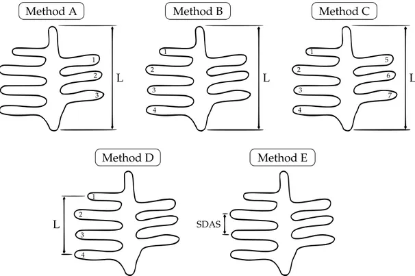
2.4.3 Measurement methods for secondary dendrite arm spacing . . . 26
2.5 Influence of the microstructure on the flow behavior of Al-alloys . . . 27
2.5.1 Dislocation hardening / strain hardening . . . 27
2.5.2 Grain boundary hardening / fine grain hardening . . . 27
2.5.3 Solid solution solidification . . . 28
2.5.4 Particle strengthening . . . 28
2.5.5 Influence of the strain rate . . . 29
2.6 Determination of the static material characteristics . . . 30
2.6.1 Portevin–Le Châtelier (PLC) effect . . . 31
2.7 Fundamentals of fatigue strength . . . 33
2.7.1 Mean stress susceptibility . . . 37
2.7.2 Determination of the experimental S-N curve . . . 37
2.8 Statistical strength theory . . . 41
2.8.1 Statistical interpretation of the finite life strength . . . 42
3 Method and implementation 45
3.1 Manufacturing procedure . . . 45
3.1.1 Melting technology . . . 45
3.1.2 Gradient solidification (Bridgman-method) . . . 47
3.1.3 Further processing . . . 48
3.1.4 Reason for the selection of this alloying elements . . . 48
3.2 Characterization of the material . . . 49
3.2.1 Specimen geometry . . . 50
3.2.2 Preparation for the microstructure analysis . . . 51
3.2.3 Determination of the cooling curve . . . 52
3.3 Investigation of the mechanical properties . . . 53
3.3.1 Tensile testing for the quasistatic properties . . . 53
3.3.2 Fatigue testing procedure . . . 54
4 Findings and analysis 59 4.1 Characterization of the material . . . 59
4.1.1 Microstructure analysis . . . 59
4.1.2 Measuring of the secondary dendrite arm spacing . . . 67
4.1.3 Thermal analysis of Magsimal-59 (+ alloying additives) . . . 69
4.2 Mechanical properties . . . 71
4.2.1 Representation of the tensile tests under static loading . . . 71
4.2.2 Results of the fatigue tests . . . 79
5 Discussion and conclusions 95 5.1 Discussion of method . . . 95 5.2 Discussion of findings . . . 97 5.3 Conclusions . . . 100 5.4 Future work . . . 102 6 Acknowledgment 103 Bibliography 105
List of Figures
1.1 Development of world production of primary aluminum (bar chart) and price in US dollars, according to [1, 72]. . . 1 1.2 Different examples for the application of Magsimal-59, [7]. . . 3 2.1 Categorization into the most important casting processes for aluminium
alloys. . . 6 2.2 Aluminium alloys are essentially based on five main alloying elements
(Mn, Si, Zn, Mg, Cu). Both age-hardenable and non age-hardenable aluminium alloys are produced on this foundation, in accordance with [14]. . . 9 2.3 Ranking aluminium alloys, focussing on the mechanical properties,
ac-coriding to [6, 7]. . . 11 2.4 Thermal analysis of Magsimal-59 from Rheinfelden. . . 12 2.5 Representation of the microstructure of Magsimal-59, from [7]. . . 13 2.6 Mechanical properties of Magsimal-59 as a function of the wall
thick-ness, according to [13]. . . 14 2.7 Crystal structure of Mg2Si (left) with the representatively highlighted
tetrahedron and octahedron (right), from [58]. . . 16 2.8 Schematic growth of primary Mg2Si crystal with ((a)-(d)) and without
((a)-(c)) Sr addition, from [55]. . . 18 2.9 Schematic of primary Mg2Si crystal with and without P addition. (1)
-(2), without P addition and (1) - (3) - (4), with P addition, from [56]. . . . 19 2.10 Schematic representation of the different formations of the Mg2Si
crys-tals by the addition of lithium, from [34]. . . 20 2.11 Schematic illustration of the relationship between a binary phase
dia-gram (right) and a cooling curve (left), according to [21]. . . 23 2.12 Representation of the isothermal plot for the Al-Mg-Si alloy
composi-tion in the triangular plot at T = 1000 K, from [37]. . . 24 2.13 Phase diagram of the Al-Mg2Si system, according to [53]. . . 24
2.14 Formation of dendrites. From initially only small local disturbances of the phase front dendrite-like structures grow, [43]. . . 25 2.15 Representation of the primary, secondary and ternary dendrite arms,
according to [25]. . . 25 2.16 Presentation of the different methods for calculating the SDAS, from [69]. 26 2.17 Characteristic values of the tensile test for Al-alloys. . . 30 2.18 Schematic σ-ǫ-curve with PLC effect and illustration of the waiting time
(tw) and falling time (td), according to [9, 65]. . . 31
2.19 Schematic diagram of a fatigue fracture surface showing the three dif-ferent stages of fatigue fracture under tension and compression stress, according to [60]. . . 33
2.20 Mechanism for extrusion and intrusion formation on the surface of a fatigue-stressed sample under local cyclic plastic deformation, based
on [40]. . . 34
2.21 The stages of fatigue failure, according to [33]. . . 35
2.22 Sinusoidal stress-time curve with characteristic values of a cycle, ac-cording to [26]. . . 36
2.23 Stress range for different load cases, according to [57]. . . 36
2.24 Classification of the S-N curve (double-logarithmic plotted) and math-ematical description, according to [17]. . . 38
2.25 Comparison of S-N curves with pronounced fatigue strength (type I, left) and without pronounced fatigue strength (type II, right), according to [33]. . . 39
2.26 Fatigue strength diagram according to Haigh for unnotched samples based on the FKM guideline. The failure criterion is represented with Rmas break, [17]. . . 40
2.27 Horizon method in a schematic S-N curve with two load levels, accord-ing to [11]. . . 42
3.1 Schematic illustration of the composition from the basic alloy and the alloying elements. . . 46
3.2 A schematic illustration of a Bridgman furnance with a display and an argon bottle. . . 47
3.3 A schematic illustration of a test speciment in mm. . . 50
3.4 A schematic illustration of a crucible and two thermocouples for the investigation of the cooling behaviour. . . 52
3.5 Schematic drawing of a tensile testing machine, according to [39]. . . 53
3.6 Representation of the MTS Landmark fatigue testing machine, from [32]. 54 4.1 Imaging of the microstructure of Magsimal-59 with TiB2by the SEM. . . 60
4.2 Imaging of the microstructure of Magsimal-59 with phosphorus by SEM. 61 4.3 Imaging of the microstructure of Magsimal-59 with strontium by SEM. . 62
4.4 Imaging of the microstructure of Magsimal-59 with cobalt. . . 63
4.5 Imaging of the microstructure of Magsimal-59 with chromium by SEM. . 64
4.6 Imaging of the microstructure of Magsimal-59 with nickel by SEM. . . . 65
4.7 Imaging of the microstructure of Magsimal-59 with zirconium by SEM. . 66
4.8 Illustration of the microstructure at different cooling rates: 6 mm/s (left), 0.3 mm/s (center), 0.03 mm/s (right). Image taken through a optical microscope at 20x magnification. . . 68
4.9 Thermal analysis of Magsimal-59 (with alloying elements). . . 69
4.10 Equilibrium phase diagram of the Al - 5Mg - 2Si - 0.6Mn - 0.2Fe - xNi alloy calculated with Pandat software, from [77]. . . 70
4.11 Stress-strain diagram for the in-house Magsimal-59. . . 72
4.12 Stress-strain diagram for Magsimal-59 from Rheinfelden. . . 72
4.13 Stress-strain diagram for Magsimal-59 with strontium. . . 73
4.14 Stress-strain diagram for Magsimal-59 with phosphorus. . . 73
4.15 Stress-strain diagram for Magsimal-59 with TiB2. . . 74
4.16 Stress-strain diagram for Magsimal-59 with chromium. . . 74
4.17 Stress-strain diagram for Magsimal-59 with cobalt. . . 75
4.18 Stress-strain diagram for Magsimal-59 with nickel. . . 75
4.20 Double logarithmic plot of the S-N curve at R = 0.1 for Magsimal-59
(in-house production). (•= break,◦= run-out) . . . 81
4.21 Double logarithmic plot of the S-N curve at R = 0.1 for Magsimal-59 (Rheinfelden). (•= break,◦= run-out) . . . 83
4.22 Double logarithmic plot of the S-N curve at R = 0.1 for Magsimal-59 (Rheinfelden) + phosphorus. (•= break,◦= run-out) . . . 85
4.23 Double logarithmic plot of the S-N curve for Magsimal-59 (Rheinfelden) at R = 0.5 and under a pure tension load. . . 87
4.24 Double logarithmic plot of the S-N curve for Magsimal-59 (Rheinfelden) at R = –1 and under a tension/compression load. . . 89
4.25 Illustration of the measured points from the experimentally determined S-N curves in a Haigh diagram. . . 90
4.26 Panorama image of the fracture surface. . . 92
4.27 Panorama image of the fracture surface. . . 92
4.28 Panorama image of the fracture surface. . . 92
4.29 Panorama image of the fracture surface. . . 93
4.30 Panorama image of the fracture surface. . . 93
4.31 Panorama image of the fracture surface. . . 93
List of Tables
1.1 Production of primary aluminum by the major countries in 2019 (in 1.000 tons), according to [63]. . . 2 2.1 Alloy groups of the aluminum casting alloys, .x stands for a number in
the designation of the Al alloy, according to [14]. . . 10 2.2 The percentage chemical composition of Magsimal-59 in wt.%, in
accor-dance to [7]. . . 12 2.3 Physical properties of Magsimal-59, according to [7]. . . 13 2.4 Properties of the intermetallic phase Mg2Si, from [68]. . . 16
2.5 Solubility of the elements in aluminum solid solution, at the eutective TE (E) or peritical TP (P) temperature, according to [68]. . . 21
2.6 Empirical formulas for the calculation of mean stress susceptibility un-der normal stress, according to the FKM guideline [33]. . . 37 2.7 Safety range for the Gaussian distribution, according to [26]. . . 41 3.1 Elements for the production of own Magsimal-59 with the required
master alloys. . . 45 3.2 Ingredients of the alloying elements as addition to Magismal-59 using
this master alloys. . . 46 3.3 SDAS in relation to the movement speed of the heat chamber vcand the
time required for complete solidification ts. . . 47
3.4 Composition of all manufactured materials in wt.%.∗Data sheet of Rhe-infelden with the limits of addition of alloying elements. . . 49 3.5 Sample preparation of the material for the further investigations. . . 51 4.1 Components of the examined phases of Magsimal-59 with titanium
di-boride. . . 60 4.2 Components of the examined phases of Magsimal-59 with phosphorus. 61 4.3 Components of the examined phases of Magsimal-59 with strontium. . . 62 4.4 Components of the examined phases of Magsimal-59 with cobalt. . . 63 4.5 Components of the examined phases of Magsimal-59 with chromium. . 64 4.6 Components of the examined phases of Magsimal-59 with nickel. . . 65 4.7 Components of the examined phases of Magsimal-59 with zirconium. . . 66 4.8 Tabular representation of the measurement results and their mean value,
as well as their standard deviation. ∗at a cooling rate of 0.3 mm/s,∗∗at a cooling rate of 0.03 mm/s. All values are given in µm. . . 67 4.9 Tabular representation of the liquidus temperature as well as the
eutec-tic temperature of all alloy compositions. . . 69 4.10 Tabular overview of the mean values and standard deviations of the
static parameters (E, Rm, Rp0,2and ǫ) for all alloy compositions. ∗from
4.11 Tabular overview of the measuring points on the load horizons at R = 0.1 for Magsimal-59 (in-house production). ∗a run-out is evaluated at ND = 2·106. . . 80
4.12 Illustration of the measuring points on the load horizons at R = 0.1 for Magsimal-59 (Rheinfelden).∗a run-out is evaluated from ND = 2·106 . . 82
4.13 Illustration of the measuring points on the load horizons at R = 0.1 for Magsimal-59 (Rheinfelden) + P.∗a run-out is evaluated from ND = 2·106 84
4.14 Illustration of the measuring points on the load horizons at R = 0.5 for Magsimal-59 (Rheinfelden).∗a run-out is evaluated from ND = 2·106 . . 86
4.15 Illustration of the measuring points on the load horizons at R = –1 for Magsimal-59 (Rheinfelden).∗a run-out is evaluated from ND = 2·106 . . 88
4.16 Presentation of the calculated (according to FKM) and experimentally determined (from S-N curve) mean stress sensitivities Mσfor all three
List of Abbreviations
ASF Audi Space-Frame
DSA Dynamic Strain Aging
DSC Differential Scanning Calorimetry
EBSD Electron Backscatter Diffraction
EDX(S) Energy Dispersive X-ray (Spectroscopy)
EN Electronegativity Value
FSD Fatigue Strength Diagram
fcc face-centered cube
HPDC High-Pressure Die (Casting)
LMF London Metal Exchange
OES Optical Emission Spectrometer
PDAS Primary Dendrite Arm Spacing
PSB Persitant Slip Band
PLC Portevin-Le Châtelier
SDAS Secondary Dendrite Arm Spacing
SEM Scanning Electron Microscope
SRS Strain Rate Sensitivity
TDAS Ternary Dendrite Arm Spacing
UTS Utilmate Tensile Strength
List of Symbols
A0 Initial cross section mm
A Cross section mm
cp Specific heat capacity J/K·kg
E Young’s modulus GPa, MPa
E0 Standard potential V
f Frequency Hz,1/s
fs Solid content %,
-H Hardness HV
jext External heat flow W
k Gradient of the S-N curve
-PA Probability of failure %
Mσ Mean stress susceptibility
-m Strain stress sensitivity
-N Number of cycles
-QL Latent heat J
R Stress Ratio
-Rm Ultimate tensile strength MPa
Rp0,2 Yield strength MPa
s Standard deviation
-T Temperature ◦C, K
TN Scattering in cycle direction
-Ts Melting temperature ◦C, K t Time s td Diffusion time µs, s ts Wall thickness mm tw Waiting time µs, s u Safety range -V Volume mm3 vd Diffusion speed m/s
αt Thermal expansion coefficient 1/10−6K
ǫ Elongation %
˙ǫ Strain rate 1/s
λ Thermal conductivity W/K·cm
λ1 Primary dendrite arm spacing µm λ2 Secondary dendrite arm spacing µm
κ Electrical conductivity S/m
ρ Density kg/cm3
σ Strength MPa
σa,i Load level MPa
σAD Fatigue strength MPa
Chapter 1
Introduction
In this chapter, a brief insight into the topic is given, including a short explanation of the task and the research question. Likewise, the tasks are narrowed down to reflect the clear content of this work and conclude with a short structuring of the thesis.
1.1
Background
Since the beginning of the industrial production of aluminum a little more than 100 years ago, this material has become the most important utility metal in our indus-trial society after steel. The demand for lightweight construction materials has been increasing more and more due to various applications (aircraft industry, automotive industry, mechanical engineering, sports, and so on). The production and processing of primary aluminum are increasing more and more, not only because it offers ad-vantages such as durability or aesthetics, but also because recyclability plays a very important role. As a result of these advantages, production has doubled in the past decades [44]. 0 10 20 30 40 50 60 70 Pr oduction of Al in 10 6·tons 0 0.4 0.8 1.2 1.6 2.0 2.4 2.8 Price for Al in $ per kg ’06 ’07 ’08 ’09 ’10 ’11 ’12 ’13 ’14 ’15 ’16 ’17 ’18 ’19 Years between 2006 and 2019
FIGURE1.1: Development of world production of primary aluminum (bar chart) and price in US dollars, according to [1, 72].
.
This graph shows the development of the aluminum price worldwide in the years from 2006 to 2019 inclusive. The price refers to the London Metal Exchange (LME) for unalloyed aluminum of high quality with at least 99.7 % purity. In 2019, the price per tonne of aluminum on the LME averaged $ 1,794.49 per year and the global refinery
production of aluminum in the years from 2006 to 2019. In 2019, around 63.7 million tonnes of aluminum were produced worldwide [1, 72]. One of the most important producers of primary aluminum in 2019 was by far China, followed by India and Russia, and more than half of the total production worldwide was produced in China (in 2019, about 36·106tons). The following table shows the most important producers
of primary aluminum in 2019 [63].
TABLE1.1: Production of primary aluminum by the major countries in 2019 (in 1.000 tons), according to [63].
Rank Country Production in 103tons
1 China 36 000
2 India 3 700
3 Russia 3 600
4 Canada 2 900
5 United Arab Emirates, Dubai 2 700
6 Australia 1 600 7 Bahrain 1 400 8 Norway 1 300 9 USA 1 100 10 Iceland 850 Σ = 55 150
As a result, the ten most important aluminum producers generate about 85 % of the total world consumption of primary aluminum. In the 2000s, production was still around 25 million tons [63]. This rapid increase can be justified by the fast growth of technology and the special properties of aluminum. These include good corrosion resistance, high strength spectrum, low specific weight, high electrical conductivity, high heat capacity and it is non-toxic, which makes it suitable for use in the food indus-try [45]. However, aluminum alone does not provide the best mechanical properties, so investigations were carried out using alloying additions. The basis for the devel-opment of material properties is the control and precise modification of the macro-and microstructure. To obtain a calculable behavior of materials, the structural change caused by certain processes must be known and the initial state must also be calcula-ble. Due to the low heat resistance of aluminum, starting to change the structure at about 250◦C, the thermal influence must be suppressed by suitable alloying elements. Besides the thermal properties, the mechanical properties must also be known [44]. For each material, a (quasi-)static, dynamic, and cyclic investigation must be carried out in order to know the fracture behavior and consequently prevent early failures. The aluminum material also received a great upswing through comparatively easy production, such as casting. During the last few years, the possible manufacturing processes and the associated properties have also grown more and more. Thus, a suit-able manufacturing type could be found for almost every field of application, such as
mold casting or die casting. Through the targeted application of manufacturing pro-cesses for the characteristics at hand, certain advantages can be used, e.g. to achieve certain geometries or to obtain the best possible strength result. In this way, the mate-rials can be matched much more economically to their possible applications, allowing a great deal of time and money to be saved [59].
Early in the history of automobile manufacturing, the issue of alternative materials to steel was discussed. However, it was not until the beginning of the 1990s that aluminum began to play an increasingly important role in the automotive industry as the topic of lightweight construction came to the foreground. This led to the first aluminum body on the market in 1993, which Audi first described as a space-frame construction (ASF). Compared to steel, the new chassis was approx. 40 % lighter and could therefore save a lot of fuel [45]. From this point on at the latest, it became clear that aluminum also plays a very important role in other areas. More and more alloys, depending on the area of application, were produced and manufactured with suit-able production processes. Increasingly more companies were now researching on the material "aluminum" so that in 1996 an unusual alloy for die casting at that time was introduced to the market: the Al-Mg-Si alloy Magsimal®-59. This type of alloy had
previously been used mainly for gravity die casting and was known above all for its excellent corrosion resistance even in seawater. However, it also offers other prop-erties and features for use in die casting that make it superior to many other alloys [7].
Applications of Magsimal®-59
Magsimal®-59 is an excellent material for die-cast parts that have to withstand high static and alternating loads and at the same time have good ductility. Typical appli-cations are structural and suspension parts in passenger cars. With the aim of dis-tributing the weight of the vehicle evenly between the front and rear wheels, the front subframe is made entirely of aluminum. The shock absorber tower is a structural part to which the suspension strut is connected. This part therefore has to withstand the static load of the vehicle weight and the dynamic shocks emanating from the suspen-sion. The part is designed with thin wall thicknesses to achieve the required yield strength while ensuring high elongation for good crash performance. The casting is joined to the surrounding profiles and wrought aluminum parts by gluing, punch riv-eting and MIG welding. Due to its excellent corrosion resistance, the part does not require any color coating [13]. The following figures show two possible applications for the material Magsimal-59.
(a) Rim, Magsimal-59, as-cast condition die casting
(b) Door construction for four-door sports car, Magsimal-59, as-cast condition die as-casting, wall thickness 2 mm
1.2
Purpose and research questions
This work aimed to investigate the material, microstructural and mechanical proper-ties of a given material from Rheinfelden Alloys GmbH. The material, in this case, is the specific material Magsimal-59, or more precisely the chemical compositions AlMg5Si2Mn. To achieve a change in the microstructure and mechanical properties, a
large number of alloying elements were systematically added and investigated. Among these are the thermal analysis of the materials, the static as well as the mechanical stress, and the investigation of the microstructure. By programming a MATLABscript, the evaluation of the fatigue tests should become automated as well, to be able to describe the behavior under fatigue loading mathematically better. The examination under the microscope, whether light microscope or SEM, should then round off the whole work. With the help of suitable technologies, such as EDS, microstructural dif-ferences will then be identified and described.
1.3
Delimitations
To keep the content of this paper from being too extensive, certain points are delib-erately excluded, which are not considered important in the context of this research question. These include, for example, the investigation of hardness, be it micro- or nanohardness, or DSC. Furthermore, no fracture surfaces from the tensile tests were examined, but only from the fatigue specimens, since the fracture surface of a fatigue specimen would provide more information than that of a static specimen. Likewise, the material was not subjected to an EBSD test, as this would not make a significant contribution. Likewise, crack propagation studies were left out, as this study would be beyond the scope. Also, for example, investigations, whether static or dynamic, under elevated temperatures were neglected, as the focus was first on the investiga-tion of mechanical properties under room temperature. Likewise, the alloys were only tested in the as-cast state and therefore not aged.
1.4
Outline
The thesis is structured as such, the theoretical background is followed by the meth-ods and implementation, then the results are presented and analyzed and finally, the findings are discussed and a conclusion is drawn. In the theoretical background, the possible casting methods are listed first, followed by a classification of aluminum al-loys and how their properties change with the addition of alloying elements. Finally, the fundamentals of static strength and fatigue strength and their statistical evalua-tion are described. In the chapter on methods and implementaevalua-tion, the producevalua-tion and processing of the specimens is described first, together with the methods used to characterize the material and describe its mechanical properties. Subsequently, the material is analyzed for microstructure, SDAS, and thermal analysis, and the results are then presented. Furthermore, the static as well as fatigue tests are also presented and analyzed. Finally, a discussion on the application of the methods used and on the results is given, as well as a conclusion.
Chapter 2
Theoretical background
In this chapter, the theoretical principles for aluminum alloys are explained. Starting with the different casting processes and their possible applications for the individual alloys. Then a classification of alloy compositions with aluminum as the main alloy-ing element and the specification of Magsimal-59, which forms the main component of this work. Followed by the addition of alloying additions in aluminum alloys and their effect on the microstructure and the mechanical properties. Furthermore, the solidification of aluminum alloys and the derivation of cooling curves to phase dia-grams. The ternary and binary phase diagrams are also explained and the growth of the dendrites is described in more detail, as this has a significant influence on the me-chanical properties of Magsimal-59. Subsequently, various possibilities for describing the flow behavior of aluminum alloys, e.g. by strain hardening or grain boundary hardening, are discussed. Finally, the fundamentals of the mechanical properties and their evaluation methods are presented. First, the basics of static tests also called ten-sile tests, and their special features are explained. Finally, the fatigue strength is speci-fied and the methods of evaluation are described in detail since this is one of the main components of this work. Mechanical fatigue of metallic materials is the process that leads to the failure of a component or material by cracking, reaching a certain crack length, or fatigue fracture. Fatigue is a progressive process in which damage develops slowly in the early stages and accelerates very rapidly toward the end. In most cases, the initiation process is confined to a small area, usually with high local stress, where damage accumulates during loading. The initiation process usually leads to a series of microcracks that may grow more or less independently until a crack becomes dom-inant by a coalescence process as the microcracks interact. Final failure occurs as an unstable fracture when the remaining area is too small to support the load.
2.1
Casting methods for aluminium alloys
The path from the melt to the casting part is based on fundamentally different casting methods. Aluminum castings can be produced by numerous different casting meth-ods and are partly limited by the process. The casting methmeth-ods also differ in terms of design freedom, minimum wall thickness, microstructure quality, and economy. In the following section, the most important casting processes are explained. The cast-ing processes can be divided into two types: those with "lost" molds (not reusable) and those with permanent molds. For casting with lost molds, the mold must be de-stroyed to remove the finished workpiece. Permanent molds, on the other hand, can be opened to remove the casting. The permanent molds are then available again for a new casting.
Among the lost molds is for example sand casting, which can be divided into many individual procedures. Permanent mold casting and die casting, on the other hand, are regarded as permanent molds, as shown in figure 2.1 [46].
❈❛st✐♥❣ ♠❡t❤♦❞s
✧▲♦st✧ ♠♦✉❧❞s P❡r♠❛♥❡♥t ♠♦✉❧❞s
❙❛♥❞ ❝❛st✐♥❣ P❡r♠❛♥❡♥t ♠♦✉❧❞❝❛st✐♥❣ ❉✐❡ ❝❛st✐♥❣
FIGURE2.1: Categorization into the most important casting processes for aluminium alloys.
In order to obtain the best possible casting, Cambell has created a list of ten rules for improvement.
1. Start with a good quality melt
2. Avoid turbulent entrainment of the surface film on the liquid 3. Avoid laminar entrainment of the surface film on the liquid 4. Avoid bubble entrainment
5. Avoid core blows 6. Avoid shrinkage 7. Avoid convection 8. Reduce segregation 9. Reduce residual stress 10. Provide location points
2.1.1 Sand casting
Sand casting is done in clay or resin-bonded sand molds made of natural or synthetic molding materials. The molding materials are less compacted than in sand casting, ensuring degassing at the lower hydrostatic pressure of the lighter molten aluminum. For the models, larger radii must therefore be provided. On the other hand, the looser densification increases the tendency to hot cracking of sensitive alloys. The process is suitable for small series and especially for prototype production. Due to the slower so-lidification compared to gravity die casting, the strength values are somewhat lower, therefore the wall thicknesses should be above three to four mm. An important advan-tage of the sand casting process is the great freedom of design. Undercuts, drillings, and mold cavities can be produced by inserted sand cores. A further advantage is a relatively simple possibility of changing or adapting the geometry, which is particu-larly important for prototype production. Such changes cause considerable costs for permanent molds [46, 5].
2.1.2 Permanent mould casting
The permanent mold casting process allows the production of accurate castings with a good surface finish. The relatively fast solidification in the permanent mold casting process results in better mechanical properties compared to standard sand casting. Taking into account the tooling costs, a wide range of series sizes can be covered. In the standard permanent mold casting process, the mold is filled by gravity, and usually in rising casting, i.e. the mold is filled from bottom to top. The main advantages compared to the sand casting process are [73]:
• better dimensional accuracy • higher surface quality
• avoidance of sand preparation
• shorter production time due to fast solidification • possibility for an automatized process
• smaller shrinkages and less porosity.
To further optimize the filling process, other variants of permanent mold casting are also used, in which the mold undergoes a rotational movement about the longitudinal axis. By tilting the mold at the start of the filling process, harmful turbulence can be avoided. As a result, the casting quality can also be improved, as there are fewer filling-related inclusions and pores in the casting [73].
2.1.3 Die casting
In die casting, the melt is pressed into permanent molds at high pressure and high speed. This process can be used to produce complex geometries as well as thin-walled castings. A big advantage of this process is that high dimensional accuracy and better surface quality can be achieved. The quality of the casting can be influenced by several parameters, such as the speed of the melt entering the mold, the casting temperature, or the selection of suitable lubricants. To reduce shrinkage porosity during the man-ufacturing process, the mold temperature can be adjusted. The rapid solidification of the melt causes the component to shrink, which can lead to shrinkage-related poros-ity. Porosity is influenced by mold filling conditions, such as melt speed, the pressure within the mold, and filling time. If the filling speed is too high, turbulence can occur in the material and insufficient speed inevitably leads to poor filling and porosity. The fill time must not be too long, as this will promote the cool-shut effect. This effect oc-curs when two currents meet, but can no longer merge properly. This can cause cracks in the material, which inevitably leads to a decrease in mechanical properties. The last parameter influencing the die casting process is the use of suitable lubricants. Gas entrapment in castings may be reduced via the use of appropriate lube and dilution ratio [8].
Kaufmann and Uggowitzer found that die casting specimens possess superior me-chanical properties due to the finer average grain size and lower porosity [24].
Otarawanna et al. documented that the interaction of liquid alloys, which have dif-ferent solid fractions, is dominantly responsible for the formation of segregated mi-crostructures, such as surface layer and shear bands [48, 47].
High-pressure die casting (HPDC)
In the HPDC process, a large compressive force (∼1000 bar) is applied to the melt until it is completely solidified. This high pressure allows all gases in the melt to be compressed and adds more metal to the mold to partially compensate for the shrink-age of the metal during solidification. Over the years, more and more processes have been developed which, depending on their use, bring their advantages. For example, a different method is classified under the following procedures:
• vacuum die casting • semisolid casting • squeeze casting
The HPDC process is divided into two further sub-categories, the cold chamber, and the hot chamber.
The hot chamber system is used with metals such as zinc, magnesium, and lead. The injection system for a hot chamber machine is immersed in molten metal from the blast furnace. When the piston pumps, it forces metal along with the nozzle and into the die [28].
The cold chamber system is used for metals that melt at high temperatures, such as aluminum, copper, and magnesium. Magnesium parts can be produced by using ei-ther system, although generally speaking small parts are made in hot chamber sys-tems, whilst large parts in cold chamber syssys-tems, as hot chamber machines have lim-ited dimensions. In this system higher pressure is used compared to the hot chamber system. The production rate of a hot chamber machine is higher than that of a cold chamber since less time is required for the pouring process [28].
The cold chamber system is divided into two different injection types: • horizontal injection
• vertical injection
Due to the higher production speed, a shorter time in the process steps can be achieved, which leads to an increase in efficiency and cost reduction. The molds are durable, thus reducing unit cost prices and more complex parts can be manufactured, there-fore decreasing the number of components requested each time [28].
2.2
Classification of aluminium alloys
Aluminum is extracted from the aluminum ore bauxite (AlO(OH)), which can be pro-cessed into pure aluminum by two processes. In the first step, the Bayer process is used to convert the ore into Al2O3. In the second step, pure aluminum is obtained
utilizing fused-salt electrolysis, the Hall-Héroult process. The aluminum extracted in this process can be divided into three levels of purity [14]:
1. Primary aluminum (with 99.5 % purity (Al 99.5H)) 2. Pure alumnum (with 99.8 % purity (Al 99.8))
3. Ultra-pure aluminum (with 99.98 % purity (Al 99.98R))
Aluminum, like all metals, has a crystalline structure and has a face-centered cubic (fcc) space lattice, which means that the atoms are arranged in the elementary cell in such a way that they form the corners of a cube with one atom in the center of each cube face. The arrangement of the atoms on the{111}planes in the fcc-space grid fulfill the condition for the densest sphere packing. On the diagonals of the {100} cube faces the atoms have the smallest possible distance. The dislocation motion, which is known as the mechanism of plastic deformation, occurs preferably on the
{111}planes in the direction of the diagonals <110> with the smallest atomic spacing. There are 4 different orientations for{111}planes, each with three different surface diagonals <110>, i.e. a total of twelve different sliding possibilities for dislocations in the fcc-lattice [44].
Pure aluminum is used only very rarely since it doesn’t bring a great benefit from a technical point of view. For this reason, pure aluminum is provided with alloy-ing elements which, dependalloy-ing on their composition and manufacturalloy-ing process, can achieve certain requirements [6]. Aluminum alloys are divided into two different cat-egories, cast and wrought alloys. Casting alloys have in general a high mold filling ca-pacity, good castability, and high contents of alloying elements (approx. ten to twelve percent). Wrought alloys have good formability and have contents of alloying ele-ments in the range of one to two percent, very rarely they can reach up to six percent. This means that the alloys per se are not differentiable based on the elements involved alone, but rather based on their contents, which makes the problem complex [14]. The alloys are then divided into age-hardenable and non-age-hardenable alloys, depend-ing on whether hardendepend-ing can be achieved by a precipitation reaction, as shown in figure 2.2.
Al
Zn Mg Cu Si
Mn
AlMn AlMgMn AlMg AlSi AlSiCu AlZnMgCu AlZnMg AlMgSi AlCuMg
non-hardenable aluminum alloys hardenable aluminum alloys
FIGURE2.2: Aluminium alloys are essentially based on five main al-loying elements (Mn, Si, Zn, Mg, Cu). Both age-hardenable and non age-hardenable aluminium alloys are produced on this foundation, in
A characteristic of all aluminum alloys is coarse intermetallic phases consisting of el-ements that are not or only limitedly soluble in solid aluminum which remain on the grain boundaries at the end of the solidification process. The foreign phrases contain typical impurities which are contained in the aluminum due to the production process (Fe, Si, ...) and are a disadvantage for the material properties. These foreign phases are usually very brittle, which leads to a reduction in toughness. To make the difference between wrought and cast alloys, as well as the main alloying elements, certain des-ignations have been introduced. Wrought alloys have a 4-digit designation and cast alloys a 3+1-digit designation. In both cases, the first number indicates which main al-loying element is involved [14]. Depending on the main alal-loying elements, aluminum casting alloys are divided into different classifications, as shown in table 2.1.
TABLE2.1: Alloy groups of the aluminum casting alloys, .x stands for a number in the designation of the Al alloy, according to [14]. Series Main alloying
elements
Properties and application
1xx.x non-alloyed, Al > 99 %
good corrosion resistance, high conductivity and ductility, low strength; e.g. for electrical cables 2xx.x Cu high strength, heat treatable, medium corrosion
re-sistance; e.g. for cylinder heads 3xx.x Si with Cu and
/or Mg
the most widely used aluminium casting alloy, good castability, higher strength than 4xx.x, heat treatable; e.g. machine parts, aircraft wheels
4xx.x Si highest castability, not heat treatable, good corro-sion resistance, e.g. for housings
5xx.x Mg medium strength, not heat treatable, good corro-sion resistance e.g. for ship components
6xx.x not used
-7xx.x Zn good corrosion resistance, naturally hardenable, not easy to cast
8xx.x Sn special materials; e.g. for bearings and bushings
9xx.x other
-Most components are produced by the die casting process, as this offers far more ad-vantages than wrought alloys. As described above, each alloy system has its own advantages and disadvantages, and depending on the application, different types of alloys are used with regard to their mechanical properties, as shown in figure 2.3. As indicated in the figure below, Magsimal-59 has excellent yield strength and elonga-tion characteristics. Furthermore, it is noticeable that the strength properties can be drastically improved by heat treatment (in the example Silafont-36). Materials of the 5xx.x series, with the alloy composition of Al-Mg, cannot be heat treated. However, Magsimal-59 belongs to the 5xx.x series and can still be heat treated due to the com-position of Al-Mg-Si. Unlike other casting alloys, the 500 series aluminum alloys do not have a near-eutectic composition. Instead, the magnesium content in the alloys is less than twelve wt.%, which is well below the maximum solubility of Mg in Al [14].
Elongation ǫ in % Y ield str ength Rp 0.2 in MPa
Static properties Crash properties Magsimal®-59 AlMg2Si2Mn Silafont®-36 AlSi9MgMn Silafont®-36 T6 AlSi9MgMn Castasil®-37 AlSi9MnMoZr Castaduct®-42 AlMg4Fe2 EN AC 44400 AlSi9 EN AC 44300 AlSi12(Fe) EN AC 47100 AlSi12Cu1(Fe,Zn) EN AC 51200 AlMg9 Alufont®-52 T6 AlCu4Ti Unifont®-90 T1 AlZn10Si8Mg
FIGURE2.3: Ranking aluminium alloys, focussing on the mechanical properties, accoriding to [6, 7].
As can be seen in figure 2.3, Magsimal-59 has the best properties in the as-cast state. It has superior yield strength and elongation, which makes this material so special. Furthermore, each material has its specific properties, depending on the alloy compo-sition and the field of application. Consequently, there is no such thing as the "perfect" material, but each material has to be matched to the area of application. This is the rea-son for the importance of knowing exactly the boundary conditions in the application. For example [7]:
Castasil®-37 = high elongation in the as-cast state, very good corrosion resistance, excellently suited for adhesive joints in automotive applications.
Alufont®-52 T6 = high strength alloy, very good polishing properties, good weldabil-ity, limited corrosion resistance.
Unifont®-90 T1 = very good mechanical polishability and machinability, good weld-ability, hardens again after e.g. heat stress caused by welding.
Magsimal®-59 = excellent mechanical and dynamic properties, very good weldabil-ity, very high corrosion resistance, excellent mechanical polishing properties. In the following thesis the main focus is put on the 5xx.x series, which has magnesium as the main alloying element and silicon/manganese as additional elements. More specifically, it is the alloy composition AlMg5Si2Mn (Magsimal®-59), which exhibits
excellent mechanical properties even in the as-cast state. Due to the high ductility value, this alloy is often used for the production of automobile safety parts.
2.2.1 Magsimal®-59 - A filigree lightness, but extremely resilient
Magsimal-59 is a registered trademark of the company Rheinfelden Alloys GmbH, which was introduced to the market in 1995. Until then, this material had been pro-duced as a mold casting, by only using the die casting process this material could suc-ceed. Magsimal-59 is categorized among the aluminum-magnesium alloys and has about five to six wt.% Mg and about two wt.% Si, which leads to the chemical compo-sition of AlMg5Si2Mn. Due to the surplus of magnesium and the low copper and zinc
content, excellent corrosion resistance can be achieved. To obtain an extremely pure alloy, aluminum is used with a purity of 99.8 % so that impurities and minor elements are minimized to a very low level. Table 2.2 shows the chemical composition and its limits or each element contained [74, 13]. Because of its chemical composition, the alloy has a slightly higher shrinkage than the aluminum-silicon alloys.
TABLE 2.2: The percentage chemical composition of Magsimal-59 in wt.%, in accordance to [7].
Al Si Fe Cu Mn Mg Zn Ti Be Others
Minimum balance 1.8 - - 0.5 5.0 - - -
-Maximum balance 2.6 0.2 0.05 0.8 6.0 0.07 0.2 0.004 0.2 Figure 2.4 shows the thermal analysis recorded with thermocouples in the quick-cup-crucible. Two reactions take place during the cooling process of the melt, the first reaction in the melt is the formation of α-aluminium at a temperature of 618◦C, the so-called liquidus temperature, and the second reaction occurs at a temperature of 594◦C, which is responsible for the formation of Mg2Si + Al6Mn or Al12(Mn, Fe)3Si2.
This is also known as the solidus temperature. The lower solidification range provides better feeding behavior and avoids hot tearing during solidification. Between 592 to 594◦C a holding point is formed where the eutectic Al-Mg2Si phase is formed [7].
0 100 200 300 400 500 600 700 800 540 560 580 600 620 640 Time t in s T e m p e ra tu re T in ◦ C
To describe Magsimal-59 completely, the main physical properties are listed in table 2.3.
TABLE2.3: Physical properties of Magsimal-59, according to [7].
Physical property Symbol Value Unit Validity range
Solidification range ∆T 618 - 580 ◦C
Density ρ 2.65 cmkg3 20◦C
Young’s modulus E 68 - 75 GPa 20◦C
Thermal expansion coefficient αt 24 10
6
K 20 - 200◦C
Thermal conductivity λ 1.1 KW·cm 20 - 200◦C
Electrical conductivity κ 14 - 16 mS 20◦C
Microstructure of Magsimal-59
The microstructure of the aluminum alloy "Magsimal-59" (also AlMg5Si2Mn) is
di-vided into two main parts, the primary α-Al phase (which is forming the dendrite arms) and the binary eutectic phase (α-Al + Mg2Si)E(which are distributed in the
terdendritic areas), as shown in figure 2.5. However, there is a third component, the in-termetallic phases, which depends on the added alloying elements (e.g. Al6Mn, Al6Fe,
...), and the primary Mg2Si crystals with regular polyhedral shape, which are located
in the centers of eutectic colonies. The magnesium/silicon ratio is largely responsi-ble for the eutectic structure, which should be between 35 and 50 % to ensure good castability and adequate feeding behavior. Magnesium goes into solution and gives a high yield strength by forming coherent and semi-coherent phases in the α-Al phase and promotes the formation of Mg2Si compounds. This is important because for good
corrosion behavior it must be ensured that no free silicon is available. Furthermore, the excess magnesium ensures a high yield strength. The eutectic Mg2Si phase forms
a thick lamellar and labyrinth-like structure. Due to the presence of coarse eutectic Mg2Si phases in the base alloy, it is more likely that cracks start in this brittle phase
and expand along with the interface between the eutectic Mg2Si and the primary α-Al
matrix. Since the fineness of the microstructure depends on the solidification rate, the geometry of the casting influences the mechanical properties [4, 70].
(a) Fine Al-Mg2Si-eutectic of Magsimal-59 (b) Coarse Al-Mg2Si-eutectic of Magsimal-59 FIGURE2.5: Representation of the microstructure of Magsimal-59, from
Mechanical properties of Magsimal-59
As already described, the fineness of the microstructure depends on the solidification rate, and the finer the microstructure, the higher the strength values. The higher the cooling rate, the less time is needed for the melt to solidify and the smaller the distance between the dendrites (SDAS = secondary dendrite arm spacing). This means that SDAS is a measure for the strength properties in the AlMg5Si2Mn alloy. Indirectly,
therefore, the wall thickness is also related to SDAS, since the thicker the component, the longer the time required for the melt to solidify. In other words, the thinner the wall thickness, the higher the yield strength, ultimate tensile strength, and elongation, as the microstructure becomes finer, as shown in figure 2.6. For the designer, this behavior of increasing properties with decreasing wall thickness has advantages, since a thin and light construction promotes the performance of the material. However, due to the higher shrinkage of this type of alloy, some recommendations regarding the complexity of the design must be considered, such as larger radii and drafts [13].
0 50 100 150 200 250 300 350 Str ength σ in MPa 0 2 4 6 8 10 12 14 Elongation ǫ in % 0 2 4 6 8 10 12 Wall thickness tsin mm UTS YTS Elongation 5mm
FIGURE2.6: Mechanical properties of Magsimal-59 as a function of the wall thickness, according to [13].
Fatigue strength plays a very important role in characterizing the mechanical proper-ties of material since most components are exposed to dynamic stress during actual use. The strength properties depend on the material, solidification conditions, casting defects, and surface conditions of the casting. Tests carried out by Rheinfelden Alloys GmbH showed a fatigue strength of σAD = 108 MPa in a test with a stress ratio of R
= –1, wall thickness of ts = 4 mm and a test frequency of f = 110 Hz. With a failure
probability of PA= 5 %, this assumes a value of approx. σAD = 100 MPa.
The corrosion resistance of Magsimal-59 is known to be very good, which also leads to its possible use in a saltwater atmosphere. Since this alloy type is also used for safety components, a test to determine the tendency to stress corrosion cracking is essential. In this test, the component was placed in a corrosive environment (35 g/l NaCl solution) and loaded to 75 % of the yield strength. This environment is then kept for 30 days to check whether the prevailing stress has reduced during this period. Up to a number of cycles of N = 106 no decrease in strength could be detected and only after exceeding this number of cycles a slight decrease could be detected [7].
2.2.2 The intermetallic phase Mg2Si
Mg2Si is treated as an intermetallic compound or phase, which consists of at least two
metallic components. These compounds do not adhere to the valence rules but have a stoichiometric ratio according to their chemical formula. The intermetallic compound "Mg2Si" has a stoichiometric ratio of 2:1, as shown in the following chemical reaction.
2Mg+Si−→Mg2Si
Intermetallic compounds usually show a brittle material behavior with a low density, but high strength and very good temperature resistance. This brittleness at room tem-perature results from the complicated structure of the phases. Their structure consists of two interpenetrating sublattices with atoms of different radii. This prevents sliding and plastic deformation and results in brittle material behavior. These compounds are formed during solidification of the melt, i.e. during the phase transition from liquid to solid and solid to solid [58]. The formation of intermetallic phases from the com-ponents leads to a reduction in the free Gibbs-energy of the alloy. The stability of the formed phases and, accordingly, the reduction of the free energy depends on certain factors, such as valence electron concentration (VEC), the crystal structure of the ele-ments, atomic radii of the components, and the difference in electronegativity values (EN) of the atoms involved [31]. The intermetallic phases can be divided into different groups depending on chemical composition, crystal structure, and properties:
Laves phases are the most common intermetallic phases and usually have the stoi-chiometric formula AB2. There are three classes of Laves phases, namely, cubic
MgCu2 (C15), hexagonal MgZn2 (C14), and hexagonal MgNi2 (C36). In these
compounds, the A atoms take up ordered positions as in diamond, hexagonal diamond, or related structure while the B atoms take up tetrahedral positions around A atoms [31, 41].
Hume-Rothery phases are B-metals (transition metals or B-group elements) in com-bination with those of the group T2and these form a new class of intermetallic
compounds in which the valence electron concentration (VEC) is considered the dominant factor. These include brass alloys of the Cu-Zn binary system or alloys of the Cu-Sn system known as bronze [31, 22].
Heusler phases are intermetallic phases of the stoichiometric composition X2YZ or
XYZ (often also called "Half-Heusler"), crystallize in an ordered fcc-based struc-ture and belong to a group of ternary intermetallics. Although the individual metals of the Heusler phases are non-magnetic, these phases exhibit magnetic properties which are used as iron-free ferromagnets [15, 31].
Zintl phases occur between intermetallic compounds with electropositive alkali/ al-kaline earth metals and electronegative elements, which have to show strongly different electronegativities. These compounds are stoichiometric, follow the octet rule and have a high ionic content [62, 31].
It follows that the intermetallic compound Mg2Si comes close to the Zintl concept.
According to the Zintl model, the valence electrons of the cations A are transferred to the anions X in a phase AmXn to fulfill the octet principle. The element X strives to
achieve the electron configuration of the following noble gas. This concept links the total number of valence electrons to the bonding of the metal atoms. According to the
Zintl concept, the phase Mg2Si can be written as Mg22+Si4−, which corresponds exactly
to this (8-N)–rule. The elements Mg and Si have the following standard potentials under standard conditions (ambient pressure and room temperature):
• E0Mg= – 2,362 V • E0Si= + 0,857 V
Due to the large potential difference and the high number of ions it is obvious that this chemical reaction is a Zintl compound.
The following table shows the physical properties of the Mg2Si-compound. TABLE2.4: Properties of the intermetallic phase Mg2Si, from [68].
Physical propteries Crystalline properties Definition Symbol Value and unit Definition Value
Theoretical density ρ 1.88 cmg3 Type of structure C1
Hardness H 460 HV Lattice structure fcc
Melting temperature Ts 1085◦C Glide plane {001}
Young’s modulus E 120 GPa Slide direction <100>
Thermal conductivity λ 8 mKW
Mg2Si crystallizes with an fcc-lattice composed of silicon atoms, in which the
tetra-hedral interstitial sites are occupied by magnesium atoms. Mg2Si crystallizes in the
space group Fm3m (No. 225) in the type of antifluorite (anti-CaF2type) with a lattice
parameter of 6,353 ˚A [68, 58].
Mg
Si
c
b
a
FIGURE2.7: Crystal structure of Mg2Si (left) with the representatively highlighted tetrahedron and octahedron (right), from [58].
In the CaF2-type or also AX2-type, the cations (Ca2+) are surrounded cubically by
eight anions (F−), whereas the anions are surrounded tetrahedrally by four cations. With the antifluorite type or A2X type, the cation and anion positions are swapped
[58, 71]. In the case of Mg2Si, the Si anions (Si4−) are surrounded cubically by eight
2.3
Effect of alloying elements on Magsimal
®-59
The mechanical properties of the AlMg5Si2Mn alloy are mainly determined by the
grain sizes of the primary α-Al phases and their solid solution composition. How-ever, the primary α-Al phase is usually coarse dendrite, which deteriorates the me-chanical properties seriously. Serving as the main strengthening phase, the eutectic Mg2Si phase is always thick acicular and coarse lamellar, leading to stress
concentra-tion and the formaconcentra-tion of crack source, which can greatly reduce the ductility of the alloy. Therefore, to refine the coarse dendritic primary α-Al phases and modifying the eutectic Mg2Si phases will be beneficial for the application of AlMg5Si2Mn alloys in
the industry [70]. The modification of the microstructure formation in different alloys can be realized by two possible mechanisms. The first is to achieve a heterogeneous nucleation, with selected alloying elements acting as nucleating particles. The second possibility offers the influence of modifiers on the solidification front, thereby chang-ing the surface energy of the growchang-ing crystals [53]. In contrast, an element can also have a negative effect on the alloy, which can be recognized by a poisoning effect. This effect is described by the fact that the modifying elements absorb the growth front and therefore limit the crystal growth [55]. Each element has a different effect on the alloy, as shown below:
Magnesium can influence the solubility of Mg2Si in α-Al and the strength of
materi-als after heat treatment. Increasing the Mg content in the alloy can reduce the solubility of Mg2Si in α-Al, increase the strength after heat treatment and move
the eutectic point in the Al-Mg2Si system to a lower Mg2Si concentration.
Simi-larly, an excess or increase in Mg in Al-Mg2Si alloys can promote the formation
of primary Mg2Si, reduce the volume fraction of the α-Al matrix and increase
the volume fraction of the eutectic phase of Al-Mg2Si. An excess of magnesium
had no obvious effect on the mechanical properties of Al-Mg-Si alloys. The ratio of magnesium to silicon is also very important for achieving the desired amount of 40 to 50 % eutectic volume fraction. This, in turn, favors sufficient castability and feeding during solidification [54, 4].
Silicon in excess in the Al-Mg2-Si composites leads to an increase in the
solidifica-tion range, impairs the diffusion of Mg and Si in the aluminum liquid, and pro-motes α-Al dendrite growth. Likewise, an excess of Si can lead to an increase in hardness and microhardness after aging and also positively influence the prop-erties of the alloy after heat treatment. By increasing the Si content, metastable δ-Al4(Mn, Fe)Si2 phases are formed, which are not very stable. However, Si is
mainly used to form Mg2Si and therefore free Si is no longer present, as this
could affect corrosion resistance [54, 4].
Manganese can be used to suppress the bad properties of iron, which are visible by needle-shaped intermetallic inclusions (FeSiAl5) in the microstructure. These
are mainly caused by the poor solubility of iron with silicon and aluminum in Al-Mg-Si alloys. The standard Magsimal-59 contains an Mn content of ap-prox. 0.5 to 0.8 wt.% and depending on the amount of excess silicon, manganese, and iron in the aluminum alloys, different phases (Al6(Mn, Fe), Al8(Mn, Fe),
α-Al15(Mn, Fe)3Si2, β-Al5(Mn, Fe)Si, δ-Al4(Mn, Fe)Si2) can form. Mn helps to make
the α-Al15(Mn, Fe)3Si2-phase grow and absorbs strength-lowering Iron phases
Iron in Al-Mg-Si-Mn alloys has a very strong influence on the mechanical properties, since ductility is strongly reduced the more Fe is present. Two different inter-metallic Fe phases are formed, the fine α-AlFeSi phase and the needle-shaped β-AlFe phase. By adding Mn, an attempt is made to prevent the brittle behavior of these intermetallic phases [27].
α-Al8Fe2Si
+ Mn-Addition
−−−−−−−−→α-Al24(Fe, Mn)6Si2
β-Al13Fe4−−−−−−−−→+ Mn-Addition β-Al13(Fe, Mn)4Si0.25
Titanium is usually added in quantities of up to approx. 0.3 wt.% in Al-Mg-Si-Mn alloys (or alloys based on the Al-Mg2Si intermetallic compound), which leads
to the formation of Al3Ti (more rarely Al2Ti) phases. Titanium influences the
microstructure formation on heterogeneous nucleation, with Ti serving as a nu-cleation particle. These serve as a substrate for the nunu-cleation of α-Al grains and primary Mg2Si crystals and by increasing Ti, the number of crystals is also
increased. This can improve the microstructure and properties of the alloys. However, titanium is usually used in combination with boron as nucleating par-ticles to obtain TiB2. TiB2offers a better nucleation basis for primary Mg2Si, due
to the coherent lattice relationship between them. By adding TiB2, the young’s
modulus, yield strength, and elongation to failure can be improved [66, 12].
Strontium is usually added in amounts of up to 0.1 wt.% to achieve an effect. With the growth of the nucleation the octahedral Mg2Si particles are formed. Under
the effect of Sr the value of V[100] decreases and the tetrakaidecahedral Mg2Si
particles are shaped while the octahedral outline still exists. With the further growth of the Mg2Si particles, the [1 1 1]-plane becomes smaller and thus
disap-pears, and accordingly the cubic Mg2Si particle is formed [55]. Figure 2.8 shows
the growth of the Mg2Si crystal, with Sr and without Sr addition.
(a) (b) (c) (d)
FIGURE2.8: Schematic growth of primary Mg2Si crystal with ((a)-(d)) and without ((a)-(c)) Sr addition, from [55].
With the addition of Sr, the eutectic Mg2Si morphology changes from a coarse
script-like to a fine fibrous form, and the level of modification increases with increasing Sr amounts. Sr shows two possible intermetallic phases during so-lidification, Al3Sr and Al4Sr. Sr in excessive amounts in Al-Si alloys can lead to
undesirable properties caused by the intermetallic SrSi2, SrAl2Si2phases. In
Al-Mg2Si compounds, Sr also has a poisoning effect on the primary Mg2Si phase.
This poisoning effect can be described by the fact that Sr absorbs the growth front and thus crystal growth is restricted. Due to the large difference between Al4Sr and Mg2Si in the lattice parameter, the lattice type and the melting point
of β-Sr (769◦C), it can be concluded that the compound is very minor as a het-erogeneous nucleus [55, 64].
Phosphorus is seen as an impurity in most alloys, such as Al-Si alloys, and must be suppressed. P appears to have a special property on the Mg2Si crystals, they
seem to change their shape from dendritic or equiaxed to polygonal shape. The addition of P also suppresses the growth velocity of <110>, which leads to a transformation of the primary Mg2Si morphology from dendritic to
tetrakaidec-ahedron, as shown in figure 2.9 [28, 56].
(1) (2) (3) (4) < 010 >
FIGURE2.9: Schematic of primary Mg2Si crystal with and without P addition. (1) - (2), without P addition and (1) - (3) - (4), with P addition,
from [56].
This tetrakaidecahedron formation by an addition of P can be explained by the fact that the rising of the nucleus causes the crystal particles to nucleate, which leads to a supersaturation that decreases rapidly during crystal growth. Further-more, the AlP-particles produced in the melt are effective nuclei for the forma-tion of primary Mg2Si phase [56, 64].
Nickel usually forms two intermetallic compounds, which one of them is often in the presence of Fe, Mn and Si, (Al3Ni & Al[100−140](Fe, Mn)[2−7]SiNi[4−9]) depending
on the amount of addition of the element. The intermetallic AlFeMnSiNi phase was found both as the primary phase and as the eutectic phase in the as-cast mi-crostructure. Usually, quantities of up to approx. two wt.% are mentioned. At a Ni content of two wt.% no intermetallic phases of Al3Ni could be found. The
Ni-rich intermetallics exhibit dendritic morphology during the primary solidifi-cation and lamellar morphology during the eutectic solidifisolidifi-cation stage. With an addition of approx. 0.2 wt.% of Ni in the Al-Mg-Si-Mn alloy, a slight increase in yield strength, a significant decrease in elongation, and a slight increase in UTS was observed. However, further addition of Ni leads to a decrease in UTS and the more significant the reduction in ductility. Likewise, an increase in Ni con-tent leads to an increase in the distance between the eutectic α-Al-Mg2Si-phase,
which indicates that the increased levels of Ni contents lower the growth veloc-ity of the eutectic Al–Mg2Si during the solidification [77, 4].