Automation of Composite Manufacturing Using
Off-the-shelf Solutions, Three Cases from the
Aerospace Industry
Andreas Björnsson, Marie Jonsson and Kerstin Johansen
Linköping University Post Print
N.B.: When citing this work, cite the original article.
Original Publication:
Andreas Björnsson, Marie Jonsson and Kerstin Johansen, Automation of Composite
Manufacturing Using Off-the-shelf Solutions, Three Cases from the Aerospace Industry, 2015,
Proceedings of the 20th International Conference on Composite Materials.
Copyright: The Authors.
Preprint ahead of publication available at: Linköping University Electronic Press
http://urn.kb.se/resolve?urn=urn:nbn:se:liu:diva-120300
AUTOMATION OF COMPOSITE MANUFACTURING USING
OFF-THE-SHELF SOLUTIONS; THREE CASES FROM THE
AEROSPACE INDUSTRY
Andreas Björnsson1, Marie Jonsson2, Kerstin Johansen3 1
Division of Manufacturing Engineering, Linköping University
Linköping University, 581 83 Linköping, Sweden
Email: andreas.bjornsson@liu.se, web page: www.liu.se
2
Swerea Sicomp, Compraser Labs
Compraser Labs, Bröderna Ugglas Gata, House 208B, 58188 Linköping
Email: marie.jonsson@swerea.se, web page: http://www.compraserlabs.se
3
Division of Machine Design, Linköping University
Linköping University, 581 83 Linköping, Sweden
Email: kerstin.johansen@liu.se, web page: www.liu.se
Keywords: Composite, manufacturing, automation, off-the-shelf
ABSTRACT
With an increased use of composite materials follows a need for rational, cost-efficient manufacturing processes. This paper explores how off-the-shelf solutions, developed for other purposes than composite manufacturing, can be used to build systems for automated composite manufacturing. Three demonstrators, each of them dealing with a specific type of material and all of them representing different manufacturing technologies for automated composite manufacturing, are presented and analyzed to find aspects that affect the ability to use off-the-shelf solutions. The three demonstrators target low to medium manufacturing volumes of complex products and they have been developed in collaboration with industrial partners within the aerospace industry. The conclusions drawn from the development of the demonstrators are that it is technically feasible to use off-the-shelf solutions in the three cases while adhering to the high quality standards of the industry. Furthermore three groups of aspects, quality aspects, product aspects and system aspects, which affect the ability to use off-the-shelf solutions for automated composite manufacturing, are identified.
1 INTRODUCTION
Composite materials have long been used for advanced, high cost applications within the aerospace sector but have, in recent years, seen a broader use both in this sector as well as in other areas like the automotive sector due to the desirable combination of low weight and high strength properties. With a broader use of CFRP follows a need for rational, cost-efficient manufacturing processes making automated composite manufacturing an important area for further research and development.
CFRP products can be manufactured using a multitude of manufacturing processes and many different material types and compositions. Many manufacturing processes still rely on a high degree of manual operations. The commercially available alternatives for automated manufacturing mainly target high manufacturing volumes and are less cost-efficient for small and complex product shapes. This paper explores an approach using off-the-shelf solutions, in many cases developed for other types of manufacturing, to provide automated alternatives for low manufacturing volumes of CFRP products and for products with complex shapes. Experiences from three demonstrators that have been developed using off-the-shelf solutions are presented together with a presentation of the types of aspects that affect the ability to use off-the-shelf solutions.
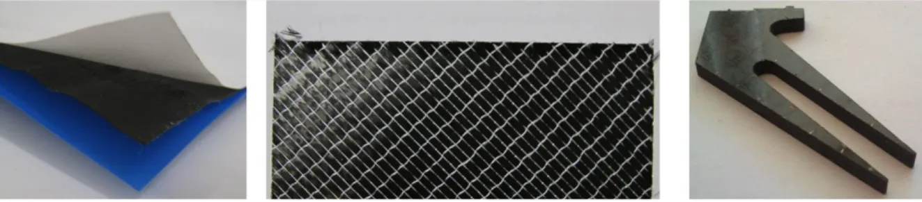
Each demonstrator deals with a unique manufacturing technology and material type. The first demonstrator is an automated pick-and-place system to layup a plies of unidirectional carbon fiber pre-impregnated with an epoxy matrix (i.e. prepreg). The second demonstrator is a system for three-dimensional ultrasonic cutting of dry carbon fiber stacks (preforms) for Resin Transfer Molding (RTM) manufacturing. The third demonstrator is an automated manufacturing cell for adhesive joining of cured CFRP materials. The three different materials used in the demonstrators are illustrated in Figure 1 below. Further technical details can be found in papers [1-3] describing the development of each demonstrator.
Figure 1: The three different types of materials used in the three demonstrators. Left: A prepreg ply protected by a white backing paper and a blue plastic film. Center: A stack of dry carbon fibers
compressed into a rigid preform. Right: A piece of cured CFRP.
The three demonstrators have been developed in collaboration with partners within the aerospace industry. This sector is characterized by high quality requirements and low to medium manufacturing volumes. The manufacturing volumes of the case products, used for the demonstrators, are ranging from around four products per year to around 25 products per week. For manufacturing operations the strict quality requirements impose a need for high process repeatability. Therefore, new manufacturing processes and new manufacturing equipment must pass rigorous validation programs in order to be allowed to be used in serial production [4]. The three demonstrators are developed to comply with the rigorous quality requirements, for example in complying with material specifications of contact materials and to provide adequate dimensional tolerances and repeatability. However, the demonstrators have not been validated for serial production. The demonstrators are targeting low to medium production volumes and are aiming to automate operations that currently are performed manually. The three demonstrators have been developed using a demonstrator centered research approach as described in [5, 6].
2 OFF-THE-SHELF SOLUTIONS, MATERIAL CHARACTERISTICS AND MANUFACTURING
Off-the-shelf solutions is a term commonly used in the IT industry where product developers make use of existing solutions in developing new software and hardware [7-9]. Experiences from the IT industry show that some of the advantages in using off-the-shelf are that development costs can be shared by many and time to market for new products can be shortened [8]. However, development methods need to be adapted to the use of off-the-shelf solutions in order to draw maximal use of the benefits that off-the-shelf solutions offer [8, 9].
In this paper the term off-the-shelf solutions is used for all solutions that are currently available either as commercial products or as well established methods. The off-the-shelf solutions are divided in to two major categories that can be further broken down as illustrated in Figure 2. The technologies category includes hardware from the lowest component level to assemblies of components to the more complex systems level. Off-the-shelf methods are established procedures for carrying out a specific task. Several procedures are, in this context viewed as a process.
Solutions Technologies Systems Assemblies Off‐the‐shelf: Methods Components/parts Processes Procedures
Figure 2: Levels of off-the-shelf solutions as presented by [6].
2.1 Prepreg Material Properties Affecting Automated Handling
A common material type used in composite manufacturing is a material where the fibrous reinforcement has been pre-impregnated with a matrix material. This type is often called a prepreg material. One of the demonstrators described in this paper uses a prepreg material with unidirectional fibers that have been pre-impregnated with epoxy resin. Prepreg materials have two characteristic properties that have a significant effect on automated handling of the material type, namely material rigidity and tack [10]. Unidirectional prepreg is highly anisotropic and sensitive to damages, thus backing paper is often used to protect prepreg materials from contaminations and damages. The backing paper also improves material rigidity making it easier to handle [10]. In composite manufacturing tack is usually defined as the ability of two prepreg plies to adhere to each other [11]. The tack is dependent on the resin type, the fiber-to-resin ratio and the temperature [10]. The tack level´s response to changing temperature is depending on material type and the tack can either increase or decrease with an enhanced temperature [12]. Adhesion between a prepreg material and another surface is, in addition to the tack level, also dependent on the contact pressure and contact time [13]. In automated manufacturing it is important to consider the prepreg adhesion and bond strength to several different types of surfaces and materials, for example adhesion to other prepreg plies and layup tools and the bond strength to the backing paper covering the prepreg material.
Manufacturing of high performance composite products made from unidirectional carbon fiber prepregs are often done by the two main approaches illustrated by the two parallel tracks in Figure 3. One approach is to place the prepreg, layer by layer, into a mold with the final product shape. An alternative to this is to stack several prepreg layers to form a multilayer stack and then form the multistack to the final shape in a separate forming process. This dual stage approach simplifies the layup operation since it generally reduces the layup from a three-dimension to a two-dimensional case.
Prepreg Cutting Layup directly on mold Debulking Cure assembly Curing Demolding Reinforcement Resin Layup of multistack Debulking Forming
Figure 3: Manufacturing approaches for manufacturing products based on prepreg materials. For automated layup of prepreg materials there are two dominating technologies, Automated Tape Laying (ATL) and Automated Fiber Placement (AFP) [14]. However, these technologies require huge investment costs and they have limitations in what types of products they can manufacture considering geometry and cost efficiency. Geometrically complex parts with, for example short lay-down lengths and sharp corners and radii, can be difficult to manufacture using AFP or ATL. For complex product geometries and for low manufacturing volumes manual layup is commonly used. In manual prepreg layup the cutting and layup operations can account for around 40-60% of the manufacturing cost of the part [15]. Pick-and-place concepts for automated handling and layup of prepreg have been developed but so far with little impact in the composite manufacturing industry [16]. Thus there is a need for automation that is suitable for low manufacturing volumes and for complex parts and for these cases pick-and-place systems for layup of multistacks is an interesting area to develop further.
2.2 Preform Manufacturing and Ultrasonic Cutting
In Resin Transfer Molding (RTM) a fibrous reinforcement is in impregnated by a polymer resin in a mold consisting of two rigid mold halves. The fibrous reinforcement can be stacked layer by layer into the injection mold or, to save cycle time, be manufactured in a separate preforming process [17] as illustrated in Figure 4. The latter creates a pre-stage called a preform which is an arrangement of dry fibers that are bound together so that it is rigid enough to be handled in subsequent operations. A common way to manufacture preforms is to cut plies of dry fibers, stack them on top of each other and bond them either by stitching or by adhesive bonding [18]. To reach a good result in the infusion process it is important that the preform fits well in the injection mold [18]. In order to simplify the stacking of dry fibers in the preforming process an over-sized preform can be manufactured and then trimmed (cut) to the correct shape so that it fits well into the injection mold.
Dry reinforcement Cutting Stacking Preform compaction Trimming Place preform in RTM mold Resin infusion Curing Demolding Resin Preforming Molding
Figure 4: Manufacturing process for RTM manufacturing of composite products [6].
Ultrasonic cutting is an established cutting technology that uses a cutting blade that is tuned to a longitudinal resonance with a frequency of 20-40 kHz and amplitude in the µm-range [19, 20]. The cutting technology is used for cutting materials such as wood, bones, composite materials and also food [21].The use of ultrasonic vibrations in cutting has shown to reduce the cutting force and the relative friction between the blade and the material as well as improve the surface quality in the cut [19, 22].
2.3 Adhesive Joining of Composite Material
Adhesive joining can be both a cost and weight efficient method for joining cured composite components [23]. Failures in adhesive joints can generally be attributed to either poor surface preparation or to incorrect preparation of the adhesive [24]. The surface preparation is therefore a very important process especially for composite materials since there is generally a wide range of contaminations on the surfaces from previous manufacturing processes [25]. Adhesives for advanced applications are generally comprised of two constituents that must be accurately mixed before application. Thus for high production volumes it is advisable to use automated mixing systems in order to achieve a stable process [26].
3 DEMONSTRATORS
This chapter presents the three different demonstrators that deal with three different manufacturing processes as well as different material types. However, they are all associated with automated composite manufacturing. Each demonstrator has been realized in collaboration with partners in the aerospace industry and they are therefore designed for an industrial context with low production volumes and high quality requirements. For each demonstrator there is a specific case product selected to provide a relevant test case. By basing the demonstrators on off-the-shelf solutions, if possible, they are developed to provide low cost automation alternatives suitable for low manufacturing volumes.
3.1 Layup of Prepreg Multistacks
This demonstrator is a pick-and-place system for automated layup of prepreg plies on a flat surface, thus creating a multistack. In order to achieve this, the demonstrator has to perform the process steps outlined in Figure 5. The case product for the demonstrator is currently manufactured using manual multistack layup followed by a forming operation. The case product is made from aerospace graded
unidirectional prepreg and the multistack consists of the plies shown in Figure 5. However, the stack showed in the figure is not the multistack that is laid up for the case product. Instead Figure 5 show a representation where all the plies have been stacked on each other to illustrate all the different ply-geometries that the end-effector, described below, need to manage.
Figure 5: Left: A process map of the tasks that the demonstrator must perform. Center and right: Two illustrations of all the ply shapes that must be managed in order to manufacture the case product [27]. To perform the process steps in Figure 5 and to handle all the ply geometries an end-effector for a standard industrial robot has been developed. The end-effector, shown in Figure 6, includes two different functions. First it includes a gripping function for lifting a prepreg ply from one surface and release it on another. Secondly it includes a function for picking up, clamping and removing the backing paper. Keeping one side of the prepreg protected by a stiff backing paper has showed to simplify the design of the gripping function. The backing paper improves the rigidity of the prepreg and provides a surface without tack for contact between the end-effector and the plies. This reduces the amount of contact points needed to support the plies and increases the possible choices of gripping technologies.
Several different off-the-shelf gripping technologies were considered for the gripping of the plies. Some of the technologies were discarded since they introduced potential quality risks, such as contamination of the prepreg material. Vacuum gripping technology was chosen for the gripping function since it offers a wide range of off-the-shelf solutions and is inexpensive. Test showed that after placing of a ply it was not possible to lift the backing paper from the prepreg using only vacuum technology, since the bond between the prepreg and the backing paper was too strong. However, if the prepreg and the backing paper were separated and then reattached the bond between them became much weaker which meant that a vacuum cup could lift the backing paper through a peeling motion. Subsequent test showed that it was enough to create this separation between prepreg and backing paper on a small area, for example a corner of a ply, to be able to remove the backing paper. To solve this, a system for generating initial separation was developed. This system was designed to be standalone, working together with the end-effector but as its own unit. In manual operations the backing paper is removed from the prepreg using a peeling motion and the same type of motion was imitated in the automated solution. However, for holding the backing paper during the pealing motion a vacuum cup was not strong enough to prevent relative motion (sliding) between the vacuum cup and the backing paper. The solution was to combine a vacuum cup with a mechanical clamping device in the end-effector. The removal of the backing paper begins by the vacuum cup lifting a part of the backing paper from the pre-separated corner fixing it using a mechanical clamping device before removing the backing paper using a peeling motion. More details on the development of the end-effector and the system for generating the initial separation can be found in [1].
Figure 6: Digital model of the end-effector. Center: The end-effector assembled on the dual-arm robot used in the demonstrator. Right: A prepreg ply picked up by the end-effector. [27]
To summarize, the decision to handle the prepreg plies with the protective backing paper attached to the plies and facing upwards at the pick-up surface simplified the gripping function of the end-effector and vacuum gripping technology proved to be suitable for the gripping function. However, handling the prepreg with the backing paper introduced the need for a backing paper removal process. The initial separation needed for the removal needed purpose-built equipment but the subsequent peeling could be made using off-the-shelf solutions. The use of off-the-shelf solutions that are commercially available showed to be advantageous since prototypes could quickly be built and tested to verify conceptual ideas. When scaling the demonstrator to handle more products the greatest challenge will be to handle the variety in ply shapes that follow with an increased product range. The number of prepreg plies was, in the demonstrator case, limited to less than 30 plies with basic shapes of roughly the same size which provided little geometrical variations between plies. More complex products than the case product will offer greater variations in prepreg shapes that will be translated to an increased demand for flexibility to handle geometrical variations in the end-effector.
3.2 Three-dimensional Ultrasonic Cutting of Preforms
This demonstrator is a system for trimming preform edges using an industrial robot and an off-the-shelf ultrasonic knife shown to the right in Figure 7. In order to fit in the intended RTM mold the preform edges must be rounded. This can be done by using multiple cuts along the edges with different chamfer angles, as illustrated below. The ultrasonic cutting demonstrator is intended to be integrated in a system for fully automated manufacturing of RTM preforms (left in Figure 7) where the same robot is used for both the trimming operation and for picking the fabric from a conventional ply cutter and stacking them onto the preform tool. Changes between the fabric handling end-effector and the ultrasonic knife are done automatically.
Figure 7: Left: Flowchart describing all the process steps in the preform manufacturing system. Center: The preform is cut to a rounded edge using multiple cuts with different chamfer angles. Right:
Demonstrator setup with industrial robot and ultrasonic knife.
Very little documentation on the topic of ultrasonic cutting, especially about cutting fibrous materials like carbon fiber preforms, could be found in published literature. However a literature review revealed a tradition of empirical testing in order to find process parameters that generated a good cut quality. The supplier of the ultrasonic knife had no previous experiences of cutting carbon
fiber materials and was also recommending an empirical approach to find valid process parameters. Tests were conducted in order to find parameters that resulted in acceptable cutting quality. The tests revealed that preform stiffness, which itself is not directly linked to the cutting process, had a great effect on the ability to produce high quality cuts. Preform stiffness is affected by the pressure and temperature used in the preform compaction process. A stiff preform showed to be easier to cut without the preform deflecting, which if it happens result in uncut layers or poor cut quality. However the stiffness of the preform also affects the permeability of the preform and can therefore not be altered without affecting subsequent RTM processes. Another process parameter that had great effect on cut quality is the level of support of the preform during the cutting operation. A well supported preform is easier to cut and seems to be less sensitive to changes in other process parameters. This means that the fixture holding the preform during cutting must be designed to provide maximal support but at the same time it must not reduce the accessibility of the knife. More detailed information about the demonstrator and the tests can be found in [2].
The use of off-the-shelf ultrasonic cutting equipment made it possible to quickly start testing and finding the proper parameter settings. Using the robot for both stacking of fabric to the preform and for the trimming operation will lower the investment costs for the entire manufacturing cell. The use of a robot mounted ultrasonic knife for the demonstrator provided a simple setup and high flexibility in parameter settings like cutting paths, angles and cutting speed.
3.3 Adhesive Joining of Cured Composite Materials
This demonstrator is a manufacturing cell for manufacturing a ring shaped product by adhesive joining of cured carbon fiber composite building blocks, illustrated in Figure 8. The demonstrator includes picking up a block from a storage area, dispensing adhesive on the block and placing it in a ring-shaped fixture. The physical demonstrator does not include automated cleaning of the surface prior to adhesive application. However, various systems for the cleaning and surface preparation have been theoretically evaluated based on their ability to be integrated in the demonstrator.
Figure 8: Left: Flowchart describing the sequence of operations. Center: The demonstrator. Right: The building blocks that are adhesively joined to form a ring shaped structure.
Tests showed that it is possible to handle the blocks using vacuum gripping technology with small vacuum cups and that the adhesive dispensing could be made using an off-the-shelf dispenser system shown in Figure 9. However the dispensing of adhesive proved to be a complicated process. Although it was possible to use an off-the-shelf dispensing system, the process had to be adapted to the current adhesive, environment conditions and to the surface the adhesive was applied on. For example, the angle between the adhesive dispensing nozzle and the surface where adhesive was applied showed to affect the risk for strings forming between the nozzle and the application point (center and left in Figure 9). These strings must either be eliminated or controlled in order to develop an automated process that is repeatable. The application pattern must also be carefully developed to the specific case and tested to avoid air pockets when adherend surfaces are pressed together and to make sure that the entire interface is coated with adhesive. More details about the demonstrator and the tests can be found in [3].
Figure 9: Left: The off-the-shelf vacuum cup and adhesive application system used for the demonstrator. Center and right: Application angle, as well as nozzle shape and adhesive type affect the
tendency of a string forming between the nozzle and the application point.
4 OFF-THE-SHELF SOLUTIONS FOR AUTOMATED COMPOSITE MANUFACTURING
The three demonstrators have shown that it is possible to use off-the-shelf solutions to automate different composite manufacturing technologies dealing with distinctly different materials. Experiences from the demonstrators show that there are several different aspects that affect the ability to use off-the-shelf solutions that are communal for the demonstrators. Some of these aspects can be grouped into the three groups: quality aspects, product aspects and system aspects.
The quality aspects are much dependent on the fact that all the three demonstrators target the
aerospace industry. The high quality standards within this particular sector impact the requirements for process validation for new or modified manufacturing processes. The validation requirements may demand procedures that range from theoretically showing similarities with already validated processes to extensive and tailored test programs. As off-the-shelf solutions generally provide a knowledgebase from previous use, these can be used to simplify the validation procedures. However the validation procedures are still determined on a case-by-case basis. The general quality requirements prevailing in the aerospace industry also have a great effect on the ability to implement off-the-shelf solutions for automated composite manufacturing. For example some silicone materials commonly used in vacuum cups must be avoided in many joining and prepreg gripping applications, due to the risk of contamination. Several off-the-shelf gripping technologies that were considered for prepreg layup could not be used as they were associated with such quality risks.
The product aspects can for example be product geometries and properties of the used materials,
which have shown to greatly affect the ability to use off-the-shelf solutions, in the cases described above. In the first demonstrator the shape and size variations of the prepreg plies was limited which made it possible to design an end-effector that could handle all the existing plies for the demonstrator using off-the-shelf vacuum gripping technologies. Increased variety in both geometrical shapes and sizes for the plies will lead to more complex end-effector designs. As for material properties one example is the prepreg adhesion to the backing paper in the first demonstrator. Since the bond is strong, extra equipment for initial separation had to be developed. For prepreg materials with a weaker bond to the backing paper this extra equipment might not have been necessary and off-the-shelf solutions might alone have solved the problem. Changes in material properties such as preform stiffness greatly affected the ability to achieve good cutting results in the ultrasonic cutting demonstrator. These two examples also illustrate the third group, the system aspects as they demonstrate that it is important to consider all the steps in the manufacturing process when designing automated manufacturing systems. A decision to simplify one process in the system can have negative effects on following process steps. For example, the decision to keep the backing paper on one side of the prepreg material in the first demonstrator simplified the gripping of the prepreg plies but required a process for automated removal of the backing paper. In the second demonstrator the a stiff, highly compressed, preform provided a simpler case for cutting but the level of compaction must also be adapted to fit with the requirements in the resin injection stage. The forecasted manufacturing volume can also be considered a system aspect that affects the possibility for automation in general. However, it can be noted that in the case of the third demonstrator the manufacturing volume of the case product
is very limited. The reason why automation is considered a viable solution for this demonstrator is because the manufacturing process is containing a large amount of highly repetitive tasks in the sequence of picking the blocks applying adhesive and placing them in a fixture. The high volume of repeatable tasks is the reason for automation, not the manufacturing volume of the final product. This observation also applies to the pick-and-place operation of prepreg plies in the first demonstrator.
5 DISCUSSION
The extensive validation and quality requirements in the aerospace industry hamper the introduction of new processes. Off-the-shelf solutions are readily available and generally low cost providing an opportunity to test new concepts in small scale experiments in order to prepare for validation. Therefore the use of off-the-shelf solutions might contribute to lowering the threshold for automating composite manufacturing.
The product aspects, such as product geometry and material type, are generally specified in the design of the final product. As changes to product properties require extensive validation they are often difficult to change in order simplify manufacturing processes or to facilitate the implementation of off-the-shelf solutions. The demonstrators have shown that automated solutions designed to manufacture only one product must handle varieties in product shapes and material properties. When developing the demonstrators further to be able to handle more products this variety will increase. Since it is difficult to change the product properties the variety in product shapes and material properties must be managed by designing automated solutions with high flexibility.
When developing the three demonstrators it has shown to be advantageous to break down the manufacturing processes in to basic, rather simple, tasks and try to find off-the-shelf solutions for each of these. With this approach it is very important to maintain a systems perspective in order to avoid sub-optimized solutions.
ACKNOWLEDGEMENTS
The research presented in this paper has been part of the NFFP-program, funded by med Swedish Armed Forces, Swedish Defense Materiel Administration and Swedish Governmental Agency for Innovation Systems, the NRFP-program, funded by the Swedish National Space Board, and the Triple Use project funded by Swedish Governmental Agency for Innovation Systems. The work of master´s students Martin Johansson, Johan Sundqvist, Andreas Haglund, Ricard Johansson, Maria Olsson and Klara Renholm is greatly acknowledged.
REFERENCES
[1] A. Björnsson, J.E. Lindbäck and K. Johansen, Automated Removal of Prepreg Backing Paper - A Sticky Problem, Proceedings of the SAE 2013 Aerotech Congress and Exhibition, Montreal,
Canada 24th-26th September, 2013, paper 2013-01-2289. (doi: 10.4271/2013-01-2289)
[2] A. Björnsson, K. Johansen and D. Alexandersson, Three-Dimensional Ultrasonic Cutting of RTM Preforms – A Part of a High Volume Production System, Proceedings of the 19th
International Conference on Composite Materials (Eds. S.V. Hoa and P. Hubert), Montreal, Canada, 28th July - 2nd August, 2013, Electronic Publishing Bytepress.com, 2013, pp.
8960-8969.
[3] A. Björnsson, M. Thuswaldner and K. Johansen, Automated Composite Manufacturing Using Off-The-Shelf Automation Equipment – A Case from the Space Industry, Proceedings of the
16th European Conference on Composite Materials, Seville, Spain, 22nd-26th June, 2014,
Paper 23.4.1-R2.
[4] A. Björnsson and K. Johansen, Composite Manufacturing: How Improvement Work Might Lead to Renewed Product Validation, Proceedings of the Swedish Production Symposium 2012
(SPS12), Linköping, Sweden, 6th-8th November 2012 (Eds. M. Björkman),The Swedish
[5] M. Jonsson, On manufacturing technology as an enabler of flexibility : Affordable
reconfigurable tooling and force-controlled robotics, Dissertation No.1501,Department of
Manufacturing Engineering, Linköping University, Sweden, 2013.
[6] A. Björnsson, Enabling Automation of Composite Manufacturing through the Use of
Off-the-shelf Solutions, Licentiate Thesis No.1692, Department of Manufacturing Engineering,
Linköping University, Sweden, 2014.
[7] D. Costa, J. Carreira and J.G. Silva, WinFT: Using off-the-shelf computers on industrial environments, Proceedings of the IEEE 6th International Conference on Emerging
Technologies & Factory Automation, EFTA '97, Los Angeles, CA, USA, September 9-12, 1997,
pp. 39-44. (doi: 10.1109/ETFA.1997.616240)
[8] D. McKinney, Impact of commercial off-the-shelf (COTS) software on the interface between
systems and software engineering, Proceedings of the 21st international conference on Software
engineering ICSE '99, Los Angeles, CA, USA, May 16-22, 1999, ACM, New York, NY, USA,
1999 pp. 627-628 (doi: 10.1145/302405.302721).
[9] C. Potts, Software-engineering research revisited, IEEE Software, 10(5), 1993, pp. 19-28 (doi: 10.1109/52.232392).
[10] R. Buckingham and G. Newell, Automating the manufacture of composite broadgoods,
Composites Part A: Applied Science and Manufacturing, 27(3), 1996, pp. 191-200
(doi:10.1016/1359-835X(96)80001-9).
[11] J. W. Putnam, J. C. Seferis, T. Pelton and M. Wilhelm, Perceptions of prepreg tack for
manufacturability in relation to experimental measures, Science and Engineering of Composite
Materials, 4(3), 1995, pp. 143-154 (doi: 10.1515/SECM.1995.4.3.143).
[12] R. Crossley, P.J. Schubel and N. Warrior, The experimental determination of prepreg tack and dynamic stiffness, Composites Part A: Applied Science and Manufacturing, 43(3), 2012, pp. 423-434 (doi: 10.1016/j.compositesa.2011.10.014).
[13] O. Dubois, J-B. Le Cam and A. Béakou, Experimental analysis of prepreg tack, Experimental
Mechanics, 50(5), 2010, pp. 599-606 (doi: 10.1007/s11340-009-9236-7).
[14] D.H.-J.A. Lukaszewicz, C. Ward and K. Potter, The engineering aspects of automated prepreg layup: History, present and future, Composites Part B: Engineering, 43(3), 2012, pp. 997-1009 (doi:10.1016/j.compositesb.2011.12.003).
[15] F. C. Campbell, Manufacturing processes for advanced composites, Elsevier Advanced Technology, Oxford, United Kingdom, 2004.
[16] C. Ward, V. Bhatnagar and K. Potter, Developing an Automated System for the Removal of Protective Films from Pre-Preg Material, to Remove a Manufacturing Bottleneck in Terms of Pick and Place Automation, Presented at SAMPE SETEC 13, Wuppental, Germany, 11-12
September 2013.
[17] K. F. Karlsson and B. T. Åström, Manufacturing and applications of structural sandwich components, Composites Part A: Applied Science and Manufacturing, 28(2), 1997, pp. 97-111 (doi:10.1016/S1359-835X(96)00098-X).
[18] S. V. Hoa, Principles of the manufacturing of composite materials, DEStech Publications Inc., Lancaster, PA, USA, 2009.
[19] G. Arnold, S. Zahn, A. Legler and H. Rohm, Ultrasonic cutting of foods with inclined moving blades, Journal of Food Engineering, 103(4), 2011, pp. 394-400
(doi:10.1016/j.jfoodeng.2010.11.009).
[20] T. Thoe, D. Aspinwall and M. Wise, Review on ultrasonic machining, International Journal of
Machine Tools and Manufacture, 38(4), 1998, pp. 239-255
(doi:10.1016/S0890-6955(97)00036-9).
[21] M. Lucas, A. MacBeath, E. McCulloch and A. Cardoni, A finite element model for ultrasonic cutting. Ultrasonics, 44, 2006, pp. e503-e509 (doi:10.1016/j.ultras.2006.05.115).
[22] Y. Schneider, S. Zahn, C. Schindler and H. Rohm, Ultrasonic excitation affects friction interactions between food materials and cutting tools, Ultrasonics, 49, 2009, pp. 588-593 (doi:10.1016/j.ultras.2009.03.001).
[23] B. T. Åström, Manufacturing of polymer composites (New ed.), Cheltenham: Nelson Thornes, Cheltenham, U.K., 2002.
[24] R. J. Crossley, S. Ratchev and A. Smith, Emerging technologies for use in aerospace bonded assemblies, SAE International Journal of Aerospace, 6(2), 2013, pp. 383-391 (doi:
10.4271/2013-01-2134).
[25] J. Wingfield, Treatment of composite surfaces for adhesive bonding, International Journal of
Adhesion and Adhesives, 13(3), 1993, pp. 151-156 (doi:10.1016/0143-7496(93)90036-9).
[26] R. Adams and J. Comyn, Joining using adhesives, Assembly Automation, 20(2), 2000, pp. 109-117 (doi: dx.doi.org/10.1108/01445150010321724).
[27] M. Johansson and J. Sundqvist, Utveckling och design av gripdon för komposithantering, Report No. LIU-IEI-TEK-A--13/01635—SE, Department of Machine Design, Linköping University, Sweden, 2013.
![Figure 2: Levels of off-the-shelf solutions as presented by [6].](https://thumb-eu.123doks.com/thumbv2/5dokorg/4582135.117456/4.892.344.550.131.365/figure-levels-shelf-solutions-presented.webp)

![Figure 4: Manufacturing process for RTM manufacturing of composite products [6].](https://thumb-eu.123doks.com/thumbv2/5dokorg/4582135.117456/6.892.287.613.125.472/figure-manufacturing-process-rtm-manufacturing-composite-products.webp)
![Figure 5: Left: A process map of the tasks that the demonstrator must perform. Center and right: Two illustrations of all the ply shapes that must be managed in order to manufacture the case product [27]](https://thumb-eu.123doks.com/thumbv2/5dokorg/4582135.117456/7.892.120.786.239.417/figure-demonstrator-perform-center-illustrations-managed-manufacture-product.webp)


