Master Thesis Project 15p, Spring 2016
Driver Safety Alert System
An Alternative to Vehicle-to-Vehicle
Communication-based Systems
Authors
Leigh Weston
Javier Marrero Reyes
Supervisor
Romina Spalazzese
Co-supervisor
Brian Katumba
Examiner
Johan Holmgren
2
Contact information
Authors:
Leigh Weston
E-mail: westonla@hotmail.com
Javier Marrero Reyes
E-mail: javier881214@gmail.com
Supervisors:
Romina Spalazzese
E-mail: romina.spalazzese@mah.se
Malmö University, Department of Computer Science.
Brian Katumba
E-mail: brian.katumba@mah.se
Malmö University, Department of Computer Science.
Examiner:
Johan Holmgren
E-mail: johan.holmgren@mah.se
3
Abstract
Automotive transport unavoidably raises safety concerns for drivers, passengers, and indeed, all road users alike. Advancements in vehicle safety technologies have come a long way, and have had a major impact on the reduction of road-related accidents and fatalities. However, as the push towards autonomous vehicle systems gains momentum, assumptions must be avoided about the global application of such technologies.
This paper proposes an idea for a road safety alert system, which is realized in the form of small-scale prototype, subsequently tested and evaluated to study its theoretical application to real world scenarios. The system is geared towards developing regions of the world where a reduction in road-related accidents and death is needed most. Reviews of various existing and proposed safety systems within the realm of Intelligent Transportation Systems (ITS) are conducted, with a focus on Vehicle-to-Vehicle (V2V) and non-V2V applications, which are compared to and contrasted with our proposal. We hope to foster further discussion and research into suitable technologies and their application, in regions of the world that require a different approach when trying to realistically reduce the consistent destructive trend of accidents and fatalities when humans are still behind the wheel.
Keywords: Intelligent Transportation Systems (ITS), Internet of Things (IoT),
4
Popular science summary
Car safety technologies have developed considerably, from passive and reactive solutions to predictive and autonomous systems. Connected cars that have joined the ever-expanding scope of the Internet of Things (IoT) allow car manufacturers, technology companies and automotive component suppliers to custom design their own take on safety features and systems, all of which aim to provide drivers with safer cars that either mitigate accidents altogether, or reduce the severity of impacts when accidents do occur. However, the vast majority of existing vehicles on the road do not even meet the basic safety requirements, and the transition to a fully autonomous driving reality is years away for many regions of the world, and at best, decades away for the rest.
The research conducted for this thesis revolves around the modelling a small scale prototype, which is studied to determine its effectiveness and accuracy in simulated real world scenarios. This allows for insight into possible limitations and overall performance considerations that must be taken into account if a full-scale model were to be built and used in a real world environment.
Two types of situations that drivers face on a daily basis will be targeted by the prototype. Designed and built as a combination of devices to be fitted to a host vehicle, it will be positioned as a system that can potentially help a large number of drivers regardless of the vehicle type they are currently driving
.
5
Acknowledgement
First and foremost I would like to thank my supervisors, Romina Spalazzese and Brian Katumba, firstly for listening to the idea, and secondly for ensuring that I stayed the course, when moments of clarity seemed elusive. Suggestions, comments and constructive criticism all helped refine the proposal and resulted in this thesis paper. Secondly, while my initial plan was to write this paper by myself, I am indebted to my colleague Javier who joined me in researching, developing, and bringing this idea to life. Finally, my heartfelt gratitude to my wife Catarina, who has always encouraged, supported and believed in everything I have done. To my parents, sister and brother who have been in my corner, always. Leigh
First of all, I would like express my sincerest gratitude to my thesis partner Leigh Weston for allowing me to join him in this venture and being such a great partner and friend. I would also like to thank my family, both from Cuba and Sweden. To those from Cuba, for encouraging me to pursue my dreams and supporting me throughout this long journey called education. To my family here in Sweden, my eternal thankfulness for taking me in and supporting me in the most unimaginable way. After many years, life gave me the opportunity to reunite with my sister and also to realize that having a second father is possible.
My gratitude to my supervisors Romina Spalazzese and Brian Katumba for their valuable support and feedback throughout this thesis.
Finally, I would also like to thank my examiner Johan Holmgren for his important comments and suggestions for improvements. Javier
6 Table of contents 1 Introduction ... 12 1.1 Motivation ... 13 1.2 Project idea... 13 1.3 Project scope ... 19 1.3.1 Developing countries ... 19
1.3.2 System vehicle and road environment ... 22
1.4 Research questions ... 24
1.5 Goals ... 24
1.6 Expected results ... 24
2 Research methodology ... 25
3 Literature review ... 29
3.1 Accident types in focus ... 29
3.1.1 Overtaking... 29
3.1.2 Rear-end Collisions ... 29
3.2 Accident prediction and prevention ... 30
3.2.1 The V2V Approach ... 30
3.2.2 The Non-V2V Approach... 36
3.3 Summary and discussion... 44
4 Results ... 46
7
4.2 Requirements for the proposed solution ... 48
4.2.1 Functional requirements (FR) ... 49
4.2.2 Non-functional requirements ... 58
4.3 Prototype ... 59
4.3.1 The software architecture ... 59
4.3.2 The hardware architecture ... 62
5 Evaluation plan ... 66
5.1 Main scenarios ... 66
5.2 Functional tests ... 67
5.3 Non-functional tests ... 74
5.4 Evaluation results ... 76
5.4.1 Limitations and challenges ... 78
6 Ethical concerns ... 81
7 Conclusions ... 82
8 Future work ... 83
8
List of figures
FIGURE 1.OVERHEAD VIEW OF COMPLETE SAFETY ALERT SYSTEM MOUNTED ON A TRUCK (HOST VEHICLE), FEATURING A ROOF
-MOUNTED CAMERA,2 RADARS (FRONT/REAR MOUNTED), AND A REAR-MOUNTED LCD DISPLAY PANEL (NOT SHOWN) . 14
FIGURE 2.COMPLETE SYSTEM OVERHEAD VIEW WITH FUNCTIONAL DESCRIPTION OF COMPONENTS. ... 15
FIGURE 3.FRONT VIEW OF TRUCK WITH HIGHLIGHTED FRONT RADAR RANGE AND THE ROOF CAMERA’S AREA OF DETECTION. .. 16
FIGURE 4.REAR-MOUNTED LCD PANEL USED TO DISPLAY WARNING MESSAGES FOR BOTH ... 17
FIGURE 5.OVERHEAD VIEW OF TYPICAL OVERTAKING COLLISION. ... 18
FIGURE 6.TOP: MESSAGES DISPLAYED FOR MEDIUM RISK AND HIGH RISK ZONE INFRINGEMENT.BOTTOM: THE RECOMMENDED MINIMUM 2-SECOND SAFE FOLLOWING RULE (THE LARGER THE NUMBER THE SAFER THE DISTANCE). ... 19
FIGURE 7.TOP TEN CAUSES OF DEATH AMONG PEOPLE AGED 15–29 YEARS,2012–WHO ... 21
FIGURE 8.ROAD TRAFFIC DEATHS BY TYPE OF ROAD USER,WHO. ... 21
FIGURE 9.THE VOLVO FH.EXAMPLE OF A LARGE TRUCK USED FOR HAULING GOODS, ALSO KNOWN IN DIFFERENT COUNTRIES AS A SEMI, TRANSPORT TRUCK TRACTOR-TRAILER, BIG RIG, AND EIGHTEEN-WHEELER, ARTICULATED LORRY. ... 22
FIGURE 10.THE VOLVO 9900.EXAMPLE OF LARGE BUSES (ALSO KNOWN AS COACHES) USED FOR INTERCITY OR INTER-COUNTRY EXCURSIONS. ... 23
FIGURE 11.A TWO-LANE ROADWAY, ALSO COMMONLY REFERRED TO AS A RURAL ROAD. ... 23
FIGURE 12.SEE THROUGH SYSTEM (STS) UTILIZES LIVE VIDEO STREAMING FROM VEHICLE TO VEHICLE. ... 31
FIGURE 13.CONCEPTUAL CONNECTIVITY OF THE PROPOSED V2V MOBILE ROUTER. ... 34
FIGURE 14.OLSR-ENABLED MULTI-HOP V2VCOMMUNICATIONS THROUGH MOBILE ROUTERS. ... 34
FIGURE 15.BMWHEAD UP DISPLAY. ... 37
FIGURE 16.VOLVO’S INTERSECTION BRAKING TECHNOLOGY;ADAPTIVE CRUISE CONTROL;DRIVER ALERT CONTROL SYSTEM. 37 FIGURE 17.TESLA'S DRIVER-FOCUSED INSTRUMENT DISPLAY SHOWS ALL THE INFORMATION THAT THE CAR HARNESSES IN ORDER TO DETERMINE ITS BEHAVIOUR IN REAL-TIME. ... 39
9
FIGURE 18.TESLA’S AUTOPILOT CONVENIENCE FEATURES PACKAGE. ... 39
FIGURE 19.AUDI’S DRIVER ASSISTANCE SYSTEMS. ... 40
FIGURE 20.SAMSUNG’S PROTOTYPE SAFETY TRUCK. ... 41
FIGURE 21.ANOTHER SAMSUNG SAFETY TRUCK PROTOTYPE. ... 41
FIGURE 22.ART LEBEDEV’S ‘TRANSPARENTIUS’... 42
FIGURE 23.AUTOMATED SUB-SYSTEM (SPEAKER REFERRED TO AS A ‘TWEETER’). ... 43
FIGURE 24.FIRST PHASE OF THE OVERTAKING (S1). ... 51
FIGURE 25.THE OVERTAKING VEHICLE IS NOW ON THE LEFT LANE (S2). ... 52
FIGURE 26.OV TRAVELS FROM S2 TO S3. ... 53
FIGURE 27.PASSING VEHICLE RETURNS TO ITS ORIGINAL LANE (S4). ... 54
FIGURE 28.MESSAGES DISPLAYED IN THE REAR-MOUNTED LCD PANEL. ... 57
FIGURE 29.PROTOTYPE SOFTWARE ARCHITECTURE ... 60
FIGURE 30.INTERCONNECTION BETWEEN THE HARDWARE COMPONENTS UTILIZED IN THE PROTOTYPE. ... 64
10
List of tables
TABLE 1:CARS WITH ADVANCED SAFETY SYSTEMS (STANDARD, OPTIONAL AND NOT APPLICABLE).INTERACTIVE TABLE WITH
VEHICLE MODEL SELECTION. ... 38
TABLE 2.TIME OF OVERTAKING MANOEUVER FOR DIFFERENT LENGTHS OF HV. ... 55
TABLE 3.HARDWARE AND SOFTWARE UTILIZED IN THE PROTOTYPE. ... 62
TABLE 4. SUMMARY OF FUNCTIONAL REQUIREMENTS AND RESULTS ... 68
TABLE 5.SUMMARY OF LIMITATIONS AND CHALLENGES FOR BOTH PROTOTYPE AND THEORETICAL FULL-SCALE / REAL WORLD SYSTEMS ... 80
11 List of acronyms ACC DGPS IEEE ITS GPS STS MANET VANET
Adaptive Cruise Control
Differential Global Positioning System
Institute of Electrical and Electronics Engineers Intelligent Transportation Systems
Global Positioning System See Through Systems Mobile Ad Hoc Networks Vehicular Ad Hoc Networks
V2V Vehicle to Vehicle
V2I Vehicle to Infrastructure V2X
WAVE
Vehicle to Everything
12
1 Introduction
In our increasingly connected world where the collection, analysis and understanding of data is used to improve upon existing technologies and create new ones, our cars, purposed with getting us from point A to point B, are being redefined. Intelligent Transportation Systems (ITS) [1] encapsulate a range of communication possibilities, of which Vehicle-to-Vehicle (V2V) communication is but one of many ITS applications. With the introduction of the connected car to the Internet of Things (IoT) [2], the automotive industry is transforming the way in which we interact with our vehicles and is also increasing our expectations of what our vehicles can and should do, as new features and services become more mainstream. As an IoT device, every vehicle has a unique identifier and the capability to connect and share data over a network [2]. And with the ability to communicate without the need for human intervention, it will evolve into a transformative technology, set to change decades old automotive business models and introduce new forms of competition, not just among car manufacturers, but between technology companies as well [3].
However, in the developing regions of the world where traffic-related accident and fatality rates are highest [4], this potentially disruptive technology [5] is either non-existent or available and accessible only to those in economically stable urban areas [6]. These economies sometimes face tremendous odds, such as socio-economic, regulatory and legal obstacles, that inhibit implementation of these technologies [7] [8]. Their automotive markets may not be deemed profitable, and money for development is earmarked for road expansion and bridge building to ease the ever increasing flow of traffic.
This thesis proposes an idea: a safety alert system that addresses two types of hazardous scenarios faced by drivers on a daily basis. The system functions independently of the ITS technology models, namely Vehicle-to-Vehicle (V2V), Vehicle-to-Infrastructure
13 (V2I) and Vehicle-to-Everything (V2X) that are coming to market, albeit, unevenly so. By designing and creating a small-scale prototype, investigation of this proposed system may prove insightful and warrant continuous research into the real world challenges and limitations of implementing such a system if it were to be built to scale.
1.1 Motivation
The driving force behind this project is to develop an idea of a technology-based safety system that reduces the number of traffic-related accidents and fatalities worldwide, without the reliance on V2V technologies. Both natives of developing Caribbean islands ourselves, Cuba and Trinidad & Tobago, we are intimately familiar with the road infrastructure, driving culture and lower standards of traffic law enforcement in these regions, and believe that other methods are required if reductions in accidents and fatalities are to be realized.
Ironically, developing countries are the regions that would benefit the most from the latest automotive safety technologies. However, taking into consideration that cars embedded with the latest safety systems are becoming increasingly more expensive [9], and that future V2V deployment in global markets will be uneven, we decided to investigate and find available components that might be combined to make a small-scale prototype version of the system idea. Using this prototype and simulated real world scenarios, we wanted to show how such a system would work and prove potentially beneficial to any driver, regardless of the make, model or year of the vehicle they are driving.
1.2 Project idea
Focusing on two specific types of traffic-related accidents, we chose to design and create a small-scale prototype safety alert system that can be used to demonstrate our proposed solution to reducing these types of accidents. Being an initial study, we are hoping that the developed prototype, demonstrated in a simulated real world environment, could be
14 seen as a simplified version of a potential solution, and justify the need for continuing research. Due to its small-scale nature, its real world feasibility cannot be proven, but the idea itself could be a real contribution to the study of solutions applicable to these real world situations.
The complete system can be seen as two subsystems (Subsystem 1, Subsystem 2) that utilize the same components to address the two different, but related, types of accidents that occur on roads everyday (Figure 1 and Figure 2
).
Figure 1. Overhead view of complete safety alert system mounted on a truck (host vehicle), featuring a roof-mounted camera, 2 radars (front/rear mounted), and a rear-mounted LCD display
15 RADAR-F - detects oncoming vehicles/obstacles and issues a “NO PASS” message alert to the rear-mounted LCD panel (LCD-R) if an oncoming vehicle has been detected
CAM-R - this roof-mounted camera has recording capabilities and is activated when an overtaking vehicle has ignored the “NO PASS” message alert and has proceeded with an overtaking manoeuvre
RADAR-R - a rear-mounted radar calculates the safe following distance, updates the distance using a weather web service, and issues warning alerts to the LCD-R.
LCD-R - rear-mounted LCD panel that displays message alerts which are triggered by radar (RADAR-F and RADAR-R)
16 The system itself is mounted to large vehicles (e.g. trucks, buses) and works as follows:
Overtaking: targeting those accidents that occur when vehicles are overtaking large
trucks or buses, Subsystem 1 uses forward-facing radar to detect oncoming traffic (Figure 3).
Figure 3. Front view of truck with highlighted front radar range and the roof camera’s area of detection.
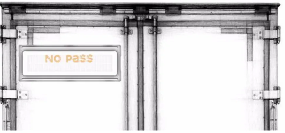
If an oncoming vehicle is detected, a warning message is displayed on a rear-mounted LCD panel (Figure 4), advising drivers against initiating an overtaking manoeuvre.
17 Figure 4. Rear-mounted LCD panel used to display warning messages for both
Subsystem 1 and Subsystem 2.
If the trailing vehicle ignores the warning message and proceeds with the overtaking manoeuvre, the roof mounted camera begins recording. In the event of an accident (Figure 5), similar to GM’s OnStar system [10], the driver of the host vehicle (truck/bus) presses an ‘emergency button’. The button performs two functions: 1) notifies emergency services and 2) uploads the recorded video footage to cloud storage. The video data allows emergency services to see the extent of the accident and the parties involved, and be therefore better prepared in their response. Law enforcement and insurance companies would also be able to have a clearer and better understanding of what transpired.
18 Figure 5. Overhead view of typical overtaking collision.
Rear-end Collisions: Subsystem 2 seeks to reduce or prevent the occurrence of rear-end
collisions, caused when trailing vehicles make contact with the rear end of a truck or bus. By utilizing a rear-mounted radar, a minimum following distance (MFD) is set (Figure 1 and Figure 2), and the driver is notified by way of messages displayed on the rear mounted LCD panel to reduce speed or increase distance depending on the proximity to the host vehicle.
Extending the system further, network connectivity allows Information to be retrieved from a weather web service. When combined with GPS positioning, conditions on the route being travelled are known and the MFD is automatically adjusted. In adverse weather conditions, and at higher speeds, the MFD should be increased. The Highway Code [11] has guidelines stating that stopping distances may be twice as long in wet conditions as opposed to dry, and up to ten times as long on icy roads [11]. The typical stopping distance is an accumulation of several factors which include: driver perception time, driver reaction time, vehicle reaction time, and vehicle braking capability [12]. However, the study in [13] has identified that for most member countries of the Conference of European Director of Roads (CEDR) [13], the 2 second rule applies (Figure 6).
19 Figure 6. Top: messages displayed for medium risk and high risk zone infringement. Bottom: the recommended minimum 2-second safe following rule (the larger the number the safer the distance).
1.3 Project scope
1.3.1 Developing countries
Safety is of paramount concern no matter where and which roadways are being used, but trying to cater to all potentially threatening scenarios that drivers face every day is not something we believe is possible right now. While various programs have been created to battle the epidemic of road-related accident and fatalities, such as the Decade of Action for Road Safety [4] [14], and new targets set to combat these high rates, such as the Sustainable Development Goals (SDG) [14], thousands of lives are being lost on a daily basis.
In developing countries, several factors influence the demand for cars. One study undertaken to address the misconceptions about private versus public transportation in developing countries [15] proposed a sociological approach to answer questions
20 regarding the demand for cars in developing regions. Income and economic status could not possibly be the sole enabler for purchase, as context would still have to be considered. In many cases, lack of transportation alternatives, value of convenience and utility as compared to the cost of car ownership, and social status [15], all potentially drive the desire to have private means of transport. In this light, the volume of cars on roads in developing countries will continue to rise, and as these countries expand their motorways and infrastructure, failure to address the need for safer practice will cost lives. Within the sustainable development goals (SDG), road safety has been targeted, with the aim of reducing deaths and accidents from road traffic accidents by half [4][16]. The Decade of Action for Road Safety that was launched in 2011 by the UN aimed to reduce the number of road fatalities worldwide to 1 million by 2020. Currently the number is 1.2 million deaths per year, and while the SDG target is higher than the one proposed by the UN, changes in road safety policies alone can have tremendous effect.
According to the Global Status Report on Road Safety 2015 by the World Health Organization [4], developing countries and regions have the highest rates of road fatalities, ranking first in the top ten leading cause of death among people aged 15-29 years (Figure 7) [4].
21 Figure 7. Top ten causes of death among people aged 15–29 years, 2012 – WHO
22 In some regions, while accidents involving 2-3 wheeled motorized vehicles and pedestrians account for the highest volume of fatalities (Figure 8), the underlying causes are the same worldwide and need to be targeted: driver distraction, lack of traffic law enforcement, varying speeds of emergency response times, and a highly disproportionate distribution of cars that do not even meet the most rudimentary international standard of vehicle safety; nearly 75% [4].
1.3.2 System vehicle and road environment
Until the world-wide deployment of affordable car and infrastructure models embedded with V2V, V2I and V2X technologies, we thought to focus our efforts on the two types of accidents previously identified - overtaking and rear-end collisions involving large vehicles.
The large vehicles we have chosen as host vehicles for the system are trucks used for long hauling (Figure 9), and buses used for intercity/inter-country travel (Figure 10). However, the prototype system that we have built is designed for use on a small-scale model truck.
Figure 9. The Volvo FH. Example of a large truck used for hauling goods, also known in different countries as a semi, transport truck tractor-trailer, big rig, and eighteen-wheeler, articulated lorry.
23 Figure 10. The Volvo 9900. Example of large buses (also known as coaches) used for intercity or
inter-country excursions.
These types of vehicles are often encountered outside of urban areas, travelling on two-lane roadways. By our definition, roadways refer to any road with one two-lane used for traffic in either direction, and with no median divider (Figure 11).
24
1.4 Research questions
RQ: What type of solution can be designed, as an alternative to V2V-based systems, to
reduce traffic-related accidents and fatalities in developing countries?
SRQ: How can the idea for the proposed system be tested and evaluated to provide
insight on how a full-scale system would work in a real world environment?
1.5 Goals
The main goal of this thesis is to propose a solution that is an alternative to existing and proposed V2V and non-V2V-based systems that aims to reduce the occurrence of overtaking and rear-end collision type accidents. Maximum system effectiveness is geared towards developing countries where V2V and current non-V2V technologies may not be implemented for some time to come, but the system may also prove useful in rural areas worldwide, where connectivity between vehicles may be less common. To achieve this, the following tasks need to be performed:
Define the requirements that are necessary to design and construct a system that will satisfy the functionality of the proposed idea.
Identify and source the components needed to build a small-scale prototype safety alert system that meets the defined requirements.
Showcase the working prototype in a simulated real world scenario, and visually demonstrate how the system works.
1.6 Expected results
On completion of this thesis, we will present a small-scale prototype which represents an interpretation of our safety alert system idea. The idea will be demonstrated by the working integration of our selected components, visually demonstrating how the system works using simulated real world scenarios. The components will all be mounted to a
25 host vehicle (small-scale truck model) with a connected laptop aiding in the visualization of the system’s functions.
Subsystem 1 (overtaking alert warning system) will detect the approach of an oncoming vehicle, display a warning message on the rear mounted LCD panel, and start recording if the trailing vehicle begins to overtake the host vehicle. The video footage will be displayed on the attached laptop that is being used to power the system and run the software.
Subsystem 2 (anti-rear-end collision alert system) will demonstrate the workings of the rear proximity sensor and the messages that are sent to the LCD panel when a trailing vehicle crosses into both of its defined hazard zones. Changing the longitude and latitude values, we will also demonstrate the minimum following distance (MFD) adjustment that occurs when weather conditions have changed in a selected region of the world.
Building a full-scale system requires resources that are not within the scope of this project. However, we expect that demonstration of the proposed system would entertain thoughts and research regarding technological solutions that could have a positive impact in regions where V2V and V2I technologies are still a long way from being economically feasible.
2 Research methodology
Based on our research questions our thesis will be driven by the Design and Creation method. The selection of this method has been clearly motivated by [17], who argues that the design and creation research strategy focuses on developing new IT products, which are also known as artefacts. Inspired by March and Smith, Oates classifies these artefacts as constructs, models, methods and instantiations. Vaishnavi and Kuechler stress that the
26 design and creation approach uses an iterative process that involves five steps (as cited in [17]).
In order to address the problem we have identified, and to meet the objectives we have set for ourselves, we will be following those 5 key steps:
Awareness: through preliminary research we have become aware of what we believe to
be a problem faced by many drivers on our roadways every year. While following large vehicles on two lane roads (one lane of traffic in either direction), drivers are often positioned too closely behind, and attempt high-risk overtaking manoeuvres when forward visibility is obstructed. When conducting our literature review at this stage, we will look at the factors that are present in these circumstances, and safety systems that try to mitigate or completely avoid accidents of this nature.
Suggestion: we have started to formulate a system to address this problem and have
decided to proceed with extensive research within the area, starting with an idea for a small-scale prototype system. This system will address two types of scenarios faced by drivers every day, and will provide warning messages when high risk conditions are detected. In specific scenarios, autonomous behaviour will lead the system to begin recording events that will provide useful when accessed and assessed by the appropriate authorities.
Development: an artefact will be designed and developed to suggest a feasible real world
system; one that is both applicable to the situations described, and has the functionality to help with the reduction of the targeted accident types. The components that are selected for the prototype will be used to demonstrate the functionality of the proposed system, and serve as suggestions for the required functionality of their real world counterparts that may have similar or more advanced functionality.
Evaluation: the performance of the prototype in a test environment will be evaluated to
27 improvements can be made. The choice of roadway plays an important role as we know that certain conditions must be in place to achieve our intended results. Those results will serve as an indicator for real world applications.
The timing and presentation of information is of critical importance, and test results will clearly reveal if these conditions are met. We are aware that a real world prototype (outside the scope of this project) will face additional obstacles, possibly in the form of national road-related protocols and government approval. However, the system idea and thoughts on its possible effectiveness if built to scale, and not its actual real world implementation, is the focus of this thesis.
Conclusion: in this final step, based on the outcome of the evaluation, we will reason
why the prototype is successful or not, and discuss the reasons for the outcome. The knowledge obtained throughout the project cycle will be used to further investigate if such a system could actually be feasible if realized full-scale and used in a real world environment. Since we cannot prove its real world feasibility even if the prototype successfully meets all its requirements, we can only discuss our results and address the limitations of the prototype system. Those very limitations could be mirrored in the theoretical real world implementation of the system, and further study to overcome them may be aided by continuous study of the prototype.
As mentioned previously in the awareness step, it was necessary to gain a deeper understanding of the problem area so that all relevant factors were identified. Furthermore, analysis of existing solutions that try to cope with these driving scenarios was of vital importance, as the knowledge gained provided a better foundation for the development process; mainly centered on the requirements and design phase. Hence, a literature review was required at an early stage of this project, and it allowed us to conclude that there is a need for a different solution, one with the intention of helping as many drivers as possible regardless of their car’s technological capabilities. We believe a system such as the one we propose is preferable to having to mount or install
28 systems/applications on every vehicle, since we can install a system on one (host) vehicle that could provide assistance to many.
The system development methodology we are utilizing is prototyping. As proposed by [17], a first prototype version is analyzed, designed and implemented. The evaluation of this version is used to improve the analysis and design models, and create a revised prototype. This process is reiterated until the prototype meets the defined requirements with consideration being given to the available resources.
The reasons for selecting design and creation as the research strategy and rejecting others are based on the main goal of this thesis and our research questions. Intending to design a system that combines existing technologies to create a safety alert prototype system for drivers, design and creation stands out as the most suitable research strategy. The above-mentioned steps composing this methodology are needed to carry out our research process.
Other strategies such as survey, experiment and case study were dismissed due to the fact that their objectives are not aligned with our purposes. By conducting surveys, researchers look for patterns that can be generalized to a larger population than the target group. On the other hand, experiments deal with investigating cause and effect relationships, whereas case studies intend to explain how and why certain outcomes might occur in certain situations [17].
At this time, we will not be conducting surveys, since we believe that asking participants what they would do in the driving situations we have identified, with the system in place, would result in biased responses. For example, it would seem unlikely that someone would say that even with a "NO PASS" warning, with prior knowledge of video recording being present, they would still engage in a high risk overtaking manoeuvre. In any event, with only an idea and a small-scale prototype to visually demonstrate this idea, the design and creation method seemed most appropriate.
29
3 Literature review
This literature review initially discusses some of the factors that lead up to, and cause, two common types of accidents that occur on roadways on a daily basis. The first are collisions which occur when drivers attempt an overtaking manoeuvre to pass a large truck or bus, and come into contact with oncoming traffic. The second, those of rear-end collisions, when a vehicle makes contact with a large truck or bus directly ahead.
To address both of these events, various systems will be identified and presented, highlighting the technologies and methods of implementing those technologies, and any obstacles that hinder their application and effectiveness in reducing or avoiding these types of accidents.
3.1 Accident types in focus
3.1.1 Overtaking
In many developed, developing, and less developed regions of the world, outside urbanized zones, rural, two-lane roadways are a common feature of the road infrastructure. These roads, with one lane of passage for traffic in either direction (Figure 11), often have no median divider - a central area dividing the opposing lanes of traffic. Overtaking, unless otherwise indicated, is permitted, with drivers having to make educated decisions, and sometimes the calculated risk, of passing a vehicle in front, based on what they see and believe to be a possible opportunity. Correlations have been suggested between driver age, attitude, frustration, vehicle type and speed [18] [19], but regardless of the cause, when collisions do occur, the results are catastrophic.
3.1.2 Rear-end Collisions
When drivers are positioned directly behind any vehicle while travelling at highway speeds, a safe distance behind the vehicle in front should be maintained at all times. This
30 distance is to allow for an adequate measure of time and space for the following driver to be able to brake and avoid contact with the rear end of the lead vehicle, if and when events occur that make sudden braking necessary. As is often the case, rear-end collisions could be avoided in some instances if this safe distance is observed; a recommended two or three-second rule [20].
The National Highway Traffic Safety Administration (NHTSA) reports that out of the 6 million car accidents that occur every year on US roads, approximately 40% are rear-end collisions [20]. In most cases, vehicle speed is at, or less than, 16 km/h (10 mph), so the vehicles themselves incur little damage. However, reports have shown that severe whiplash can still occur [21]. At highway speeds however, severe damage is incurred depending on the speed and angle that impact occurs, often resulting in death, or physically life-altering injuries. Impact with larger vehicles often results in consequential damage by several degrees.
3.2 Accident prediction and prevention
3.2.1 The V2V Approach
Looking ahead to a not too distant future, the autonomous vehicle will usher in a new era of automotive transport, with vehicles having the ability to take over the task of driving, by default (driverless taxis) or at the request of the driver when he or she chooses (autonomous). In order to achieve this, the vehicles will be fitted with all manner of technologies, including, and not limited to, ultrasonic sensors, odometry sensors, Lidar (Google), video cameras and radar sensors. All of these technologies are available today, and over time they will become more advanced, more reliable and cheaper to produce. Connecting these systems to a network means that car manufacturers and technology companies can harness the information gathered by the onboard systems and process it in real-time. Immediate action can be taken in the event of an accident, as demonstrated
31 with GM’s OnStar systems [10], or data can be stored and analyzed to improve offerings in the next software update, as in the case with Tesla’s over-the-air updates [22].
We have chosen to study select V2V systems because we strongly believe that this technology is the solution to the prevention of road-related accidents and fatalities. However, at present, specifically addressing the issues regarding safe overtaking, the use of V2V communication by its very nature requires that all vehicles in the vicinity be connected, so drivers can be made aware of all potentially hazardous conditions and situations.
One example of this idea extends the communication further by streaming live video from car to car (Figure 12). This See Through System (STS) presented by [23] relies on Vehicular Ad-Hoc Networks (VANETs), using IEEE 802.11p/WAVE (Wireless Access in Vehicular Environments) standards.
32 A drawback identified by the researchers themselves revealed that the data load of the channel increased rapidly when groups of vehicles were about to meet. They addressed this problem by proposing a power control approach which allowed them to alternately increase and decrease the transmission power from one vehicle in their test scenario. By increasing the power, they hoped to minimize packet data loss due to interference on the wireless signal. Decreasing the power after the initial data packet was received reduced collisions between packet data being broadcasted from other vehicles.
The application of V2V technology in this manner certainly provides a possible solution to high risk overtaking situations where large vehicles on rural roads obscure forward visibility of drivers behind. Using a visual display unit also means that on winding, twisty roads, guessing about what may lie ahead around the next bend is no longer necessary, as drivers will literally be able to see around corners. However, if the vehicles in this scenario are not equipped with the necessary hardware, or network connectivity is lost for any amount of time, the system would be rendered ineffective. Our proposed solution, while enhanced when connected to an available network, does not rely on that network to achieve its fundamental task, still capable of detecting oncoming traffic and presenting notification of that information to drivers following behind. However, further research is necessary to solve the issue of oncoming vehicle detection when winding roads or hills are encountered.
Authors in [24] propose an overtaking assistant that notifies drivers of trailing vehicles when it is safe to overtake, based on the calculated available time until oncoming vehicles arrive. This time frame is predicted by taking into account several variables, such as speed of the vehicle, speed of the preceding vehicle (host vehicle), and the acceleration capabilities of the subject (following) vehicle. The system comprises a simple light that is placed next to the rear mirror of the subject vehicle, which will turn green when an overtaking opportunity has been detected. Conversely, the light turns red if the identified gap until the next opposing vehicle is less than a predefined time frame.
33 This idea is assessed through a driving simulator that creates the environment with the required information provided by the system (road, preceding vehicles and speed of preceding and oncoming traffic), since the generation of such data in a real word system involves V2V communication between all vehicles and the use of GPS [25].
While this solution provides the same functionality as our proposed system, in that drivers are given a signal when passing is inadvisable, flashing a green light to indicate a possible passing opportunity assumes that the system is not only correct in its assessment of the environment, but is also encouraging the manoeuvre. We feel that an overtaking manoeuvre should only be performed when it is either necessary and/or safe to do so, and not performed just because it can be done. In this light, we have chosen not to indicate a “PASS” or “ALL CLEAR” message and instead leave that option entirely up to the following driver’s discretion.
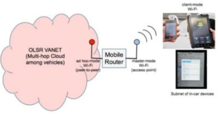
Researchers in [26] recognized that one of the major hurdles to the implementation of V2V technology was not the technology itself, but rather the legislation and time required to get it approved. A perfect example of this is the allocation of the frequency spectrum that the proposed systems could use. In the U.S. and Europe, the 5.9 GHz frequency band has been dedicated to V2V communication, and in Japan, the 5.8 GHz [26]. For this reason, the researchers in the project set about implementing a system consisting of low-cost routers that could be installed on vehicles and create a network of connected cars without any need for expensive overhead or lengthy legislative requirements (Figure 13).
34 Figure 13. Conceptual connectivity of the proposed V2V mobile router.
Prior research was conducted in 2006, which revolved around Mobile Ad hoc Networks (MANET), and then two years later research on Vehicular Ad hoc Networks (VANET) [26] began. By using readily available hardware and the IEEE 802.11 Wi-Fi standard for over-the-air communication, focus on software development and testing could be more readily achieved. Their test results showed that it was indeed possible to create an ‘Internet of Cars’ environment (Figure 14) using relatively low-cost equipment that works in an urban environment. Limitations of the technology and testing of the system were acknowledged, but the potential was proven by a working system.
35 This type of system would be ideal in regions where V2V technology implementation is not expected soon, and cost-effective alternatives need to be used. However, the success of such a system would rely on the amount of vehicles having the system installed and the range of network transmission. As stated in their paper, the system was successfully tested in an urban environment, whereas our system is geared more towards rural and highway areas.
A more ambitious approach to the safe overtaking scenario is the automation of this manoeuvre, as described in [27]. The authors of this paper propose a stereo vision system that can be incorporated to autonomous driving vehicles and control the overtaking process. The system is equipped with a vision system, comprising a forward looking camera and a rear looking camera, a positioning-based system consisting of a differential global positioning system (DGPS), and an inertial measurement unit (IMU). Using the inputs of the aforementioned components, the system outputs different actions on the autonomous vehicle's actuators, i.e., the steering wheel, throttle and brake pedals.
This system was tested in a real environment using a commercial car, showing encouraging results while overtaking different types of vehicles. Nevertheless, this solution is limited to satisfy constraints on overtaking time and safety in the lateral displacement, and does not factor for detection of oncoming traffic via stereo vision at the current stage [27].
V2V communication would seem to be the best way to possibly assist drivers in overtaking scenarios, and another solution with its use is presented by Vieira et al. [28]. In this study authors develop a coordinated positioning message broadcast protocol among vehicles utilizing VANET as communication platform. Since messages are broadcasted throughout a transmission range it is possible to know the position of adjacent vehicles in advance even if they are a relatively long distance away. The message exchange enables knowledge of information about other vehicles in the VANET vicinity transmission range, which, when combined with kinematics, allows the
36 prediction of safe overtaking manoeuvres with minimum near-collision or no accident risk [28]. The proposed solution is also evaluated at an experimental level, with controlled scenarios generated by simulation tools.
A cooperative overtaking assistance system is offered in [29]. The proposed on-board architecture is composed of four main subsystems. First, a required communication subsystem is needed for the exchange of messages containing data about the emitting vehicle’s position, speed and time, with surrounding vehicles. To gather such information a navigation system is needed, which provides inputs for the collision detection logic executed by the on-board system. Data exchange between vehicles is executed using the cellular network.
The sequence of events begins when a lane change is detected; this information derived from the navigation unit. The communication system then alerts neighboring vehicles about the lane change. If no vehicles are detected the system keeps looking for lane changes. On the contrary, if a message is received from another vehicle (or vehicles), the collision prediction algorithm is used to analyze a potential collision, and if one is identified, the system alerts the driver of the subject vehicle and sends another message to the oncoming vehicle [29].
3.2.2 The Non-V2V Approach
With advancements in automotive safety technology, drivers today are presented with a wide range of standard and optional safety features. Mercedes Benz offers a range of systems such as: Collision Prevention Assist, Active Blind Spot Assist, Attention Assist, Steering Assist, Active Headlights, and Active Lane Keeping Assist [30]. BMW, on their flagship 7 series sedan [31] [32] offers Night Vision with Person Recognition, Driving Assistant Including Steering and Lane Control Assistant, and the BMW Head-Up Display (Figure 15).
37 Figure 15. BMW Head up display.
Volvo, a company known for safety, has improved on their stellar reputation by offering several systems (Figure 16) such as: Adaptive Cruise Control with Pilot Assist, Park Assist Pilot/Front Park Assist and Blind Spot Information System & Cross Traffic Alert [33] on their new XC90 SUV.
Figure 16. Volvo’s Intersection Braking Technology; Adaptive Cruise Control; Driver Alert Control System.
Tesla [34], a company that produces fully electric sports cars, is the only company that offers the latest safety systems as standard features on their models (Table 1) [35]. Their cars feature highly graphical information clusters that allow the vehicle to determine its future actions relative to its current surroundings (Figure 17).
38 Table 1: Cars with advanced safety systems (standard, optional and not applicable). Interactive
39 Figure 17. Tesla's driver-focused instrument display shows all the information that the car
harnesses in order to determine its behaviour in real-time.
However, the Tesla Model S and Model X retail for $71,000 US and $81,000 USD respectively [34].
Tesla’s Autopilot feature is their take on an overtaking system which combines a camera, a radar and 12 sensors [36]. When the vehicle is put in cruise control mode, if the driver turns on the indicator signal, the car will automatically increase its speed and pass slower moving traffic ahead (Figure 18).
40 Concerns have been raised about the incurred liability if an auto-overtaking manoeuvre is the cause of a subsequent accident. Tesla has responded with the argument that when a driver activates a turn signal, the driver should in fact be aware that road conditions are appropriate for a lane change, even if the car itself then executes the overtaking manoeuvre [36]. The driver would then in fact be liable; not the car (company).
Audi’s active safety systems [37] incorporate a variety of devices responsible for obtaining data about the car’s environment, and then uses that data to inform drivers of potential risks (Figure 19). To have access to all these features though, potential buyers would have to check everything on the options list.
Figure 19. Audi’s driver assistance systems.
Outside the realm of the car, Samsung introduced their Safety Truck [38] in 2015 at the Cannes Lions advertising festival and won numerous awards. Their truck was also selected as one of the best 25 inventions for 2015 by Time Magazine [39]. Aimed at reducing accidents involving vehicles overtaking other large or larger vehicles that
41 obstruct forward vision, the truck features two wireless cameras at the front which stream a live video feed to large Samsung OHD screens mounted at the rear (Figure 20 and Figure 21).
Figure 20. Samsung’s prototype Safety Truck.
42 This idea was first proposed in 2009 by the Russian design house, Art Lebedev [40], but never moved past the concept stage (Figure 22). Even now, 7 years later, practical and commercial considerations are in question, especially with the impending rise of V2V and V2I technologies. The Samsung truck is actually a reintroduction of this concept.
Figure 22. Art Lebedev’s ‘Transparentius’.
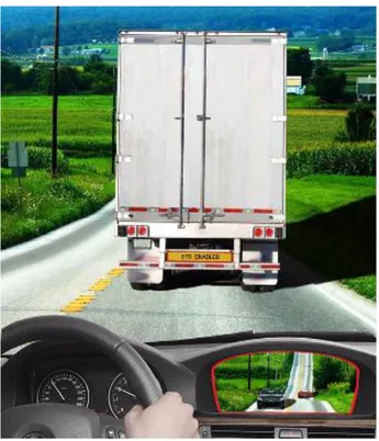
Lastly, a road safety mechanism proposed by researchers [41] aimed specifically to prevent overtaking accidents involving large trucks, is presented in this review. This proposal is the most closely related system to our own that was found, in that it utilized, amongst other components, proximity sensors and a camera in a non-V2V configuration. When activated, the rear-mounted proximity sensors are used to detect a trailing vehicle,
43 which then triggers the camera, allowing it to record and stream its output to the right side mirror of the truck that was refitted with a video monitor (Figure 23).
The driver of the truck would then be notified by way of an audible alert, and would have the responsibility to check for oncoming traffic. If the driver determines that the roadway ahead is clear, he or she can press one of two dashboard mounted buttons, lighting a green indicator light at the rear of the truck to signal to the trailing driver that it was safe to pass, or the other, to turn on a red light, indicating that the road ahead is not clear.
Figure 23. Automated sub-system (speaker referred to as a ‘tweeter’).
While it is commendable that this system was built to scale and fitted to a real truck, we believe it to be ultimately flawed for the overwhelming reason that the driver of the truck has the responsibility to notify the driver (or drivers) behind that overtaking is both possible and safe. The fact that the paper went on further to also describe an in-dash camera system used to monitor the truck driver’s face to detect closed or ‘drooping eyes’, suggests that our almost fully autonomous system, if realized, would reduce human miscalculation, distraction and unawareness for both the driver of the host vehicle (truck) and the drivers behind it.
44
3.3 Summary and discussion
Grouping the articles into V2V and non-V2V solutions, the distinction was made between the different approaches that car manufactures use to increase car safety. The V2V solutions are dependent on all vehicles in the scenario having network connectivity, and a stable network on which to connect. For developed countries, and those financially committed to V2V and V2I implementation, it may just be a matter of time before car manufactures are able to offer these technologies as standard equipment on their more affordable models. If not, then V2V projects such as the ones reviewed here might have the possibility to become commercialized once testing is complete and regulations are met.
In less developed regions where connectivity may be unavailable, or at the very most, unstable, consumer automotive purchasing power may be lower and 3rd party solutions would still have to be purchased by a vast majority of drivers to experience the intended benefits. In some developing countries, a lot of time and money is spent on the construction of new roads and bridges to alleviate the increase of cars [8], while safety (educational and technological) is a secondary concern.
In the non-V2V context, where the use of radar, sensors and software to run the algorithms that are essential to the delivery speed and accuracy of the measurements that these components take, challenges arise with the cost of implementation. Those car manufactures who have managed to bring the vast array of safety technologies to the market have done a brilliant job of packaging, marketing, promoting and educating the public about these systems, but there is still a void. The vehicles in which these systems are found are in some cases well above the average cost of a new car [9] [21], or the systems themselves drive the cost of the vehicle upwards, as they are now found on vehicles that have a higher build quality, better warranties and more efficient engines [9].
45 In the case of overtaking systems, the research projects identified in this review either rely on V2V communication in order to function safely, or in the case of Tesla, require a $61,900 USD investment (base model Tesla S) [42]. Adaptive Cruise Control (ACC) systems while certainly an improvement on standard Cruise Control systems that remain engaged at a fixed driver-selected speed, do not adjust to changes in weather/road conditions. Drivers are advised to not engage the system when conditions are not ideal, or the system itself cannot be engaged, or is disabled in less than ideal conditions [43]. Additionally, drivers have the option to select a following distance themselves, which in effect defeats the purpose of decidedly maintaining a fixed safe minimum following distance at which one should follow.
The inspiration for our idea, the Samsung Safety Truck, is a prime example of a system that is catered for certain types of roadways in countries with different driving cultures and a need for a different approach to increasing safety. While we initially thought the idea, and the execution of the prototype, to be impressive, our main areas of concern revolved around the cost to implement the system (cost of the four high definition weatherproof rear mounted screens), system performance in all weather conditions (image visibility and contrast), and ultimately the still to be documented impact on the final decision of the driver, who is now presented with more visual information than ever before.
What truly differentiates our proposed solution from the others identified here is that we accept the inevitability of human error when behind the wheel. Knowing and accepting that we cannot control the decisions that will be made, we chose to focus on presenting clear, unambiguous and timely information to drivers who find themselves in these situations on a daily basis, and thereby hope to influence the decision making process, thus reducing the potential for risky behaviour. With autonomous activation and operation, the driver of the host vehicle only has the responsibility of pressing a single button to notify the appropriate authorities.
46 The Samsung model does present another level of visibility to the driver behind, but that driver is still faced with making a calculated decision based on what is being visually perceived. Our proposed system goes a step further by calculating the time to impact of an approaching vehicle and explicitly notifying the following driver not to perform an action if the calculated time is too short. There is no need for the driver to possibly miscalculate the time or distance needed.
With respect to any IoT system, if connectivity is lost, it is no longer an IoT system, and likewise, V2V and V2I technologies would be rendered useless if connection failure or compromise occurs. Our system, particularly that of the rear anti-collision subsystem (Subsystem 2) will retain its basic functionality in the event of network failure or intermittent connectivity, and so is suitable for a wide range of global regions where this may often be the case.
4 Results
In this chapter the main results of previous research work are discussed. The factors relevant to scenarios where the system is applicable are described, together with the requirements that need to be achieved. Additionally, the developed prototype is presented, with description of the hardware and software elements utilized to make it functional.
4.1 Research results
In order to answer RQ1 (What type of solution can be designed, as an alternative to V2V systems, to reduce traffic-related accidents and fatalities in developing countries?), we conducted the literature review with a focus on current and proposed V2V and non-V2V solutions that aim squarely on the two types of accidents we have chosen to focus on.
47 We also found that previously conducted research has shown that a significant number of traffic-related accidents occur due to ill-timed overtaking manoeuvres and avoidable rear-end collisions [20]. Accidents resulting from overtaking manoeuvres are more likely when drivers find themselves on two-lane roads (one direction of traffic in each direction), where the probability of collisions with oncoming traffic rises when drivers behind other vehicles miscalculate the needed time and distance to perform a pass. The situation is more critical when drivers are behind large vehicles which obstruct the view ahead. Several factors need to be taken into consideration in these scenarios, including the speed of the vehicle being overtaken, the speed of oncoming traffic, distance to impact1, time to impact2, distance covered during the manoeuvre, and the necessary time required to complete the pass. The estimation accuracy of such variables differs between drivers (experience level), vehicle capability (engine torque, acceleration, performance) and road conditions (available traction, road surface condition).
Some of the solutions detailed in the literature review present drivers of trailing vehicles with a view of the road ahead using See Through Systems (STS) [23]. These solutions have been implemented using both V2V [22] and non-V2V configurations [33] [37]. The STS approach, although providing more visual information, still leaves room for miscalculation, especially due to differences between what is being perceived on-screen via the live stream, and what is actually occurring in the real world. Another variant intending to assist drivers during overtaking manoeuvres use V2V communication to exchange information between vehicles [23] [26]. This information includes speed and position information (the variables used to perform the corresponding calculations) and issue warning messages between vehicles to notify drivers when it is unsafe to overtake. The notification processes themselves vary in design.
1 Distance from the passing vehicle (when it starts the overtaking manoeuvre) to the oncoming vehicle
48 Adaptive Cruise Control systems (ACC) as noted before, excel at addressing rear end collisions scenarios. Nevertheless, these systems do not modify the safe following distance according to weather conditions, and in some cases the system is disabled when conditions are not ideal [43]. Another downside is that drivers can set the desired following distance, possibly rendering the system less effective if the recommended safe following distance can be decreased.
In the following section the overall requirements of the proposed solution and the needed components to accomplish them are explained. The prototype is described, and its hardware and software components are listed and detailed.
4.2 Requirements for the proposed solution
The two types of accidents mentioned above share similar variables that determine the final outcome. Special attention must be paid to the speed of the vehicles involved, and the distance and time variables as well, since they are interdependent when various calculations are made. Based on the problems of the previously presented solutions detailed in section 3.3, Summary and Discussion, we propose an alternative solution. It is to be mounted on large vehicles (trucks and busses) and can provide drivers behind with important information regarding safe overtaking opportunities and recommended following distances.
This information can be helpful to all trailing drivers regardless of the make, model or year of vehicle they are currently driving. The system should also be able to record the sequence of events leading up to accidents that occur when overtaking manoeuvres are initiated despite a “NO PASS” display indicated by the system. In the following section we list and explain the functional and nonfunctional requirements of our proposed solution.
49
4.2.1 Functional requirements (FR) FR 1- Activate/deactivate system
The system will be activated when a minimum speed of 70 km/h is reached. Since rural roadways with two lanes, one for each direction of traffic, are the main focus, the system will be automatically disabled when entering urban areas where the speed is lower.
FR2 - Measure speed of oncoming traffic, calculate time to impact3 and determine whether it is safe or not for drivers behind the host vehicle4 to overtake.
Based on the readings from the front-facing radar, which provides the distance to an oncoming vehicle, the system will calculate its relative speed. This is achieved by measuring the oncoming vehicle’s distance at one second intervals, subtracting that value from the previous reading, and then subtracting the speed of the host vehicle.
𝑽𝒐𝒗 = (
𝑫𝒐𝒗(𝒕)−𝑫𝒐𝒗(𝒕+𝟏)𝟏𝒔
) − 𝑽𝒉𝒗
(1)Where,
Vov is the speed of the oncoming vehicle,
Dov(t) is the distance to the oncoming vehicle at certain point in time (t),
Dov(t+1) is the distance to the oncoming vehicle one second after the previous measurement (t) and
Vhv represents the speed of the host vehicle.
To illustrate, we use the following values in an example:
3 Time it takes for the host vehicle to come into contact an oncoming vehicle (head on)
50 The distance measured at time t from the host vehicle (Hv) to an oncoming vehicle (Ov) is 800 m Dov(t). One second later, Dov(t+1), the distance has been reduced to 750 m. This indicates that both the Hv and the Ov have covered a total of 50 meters in the one second that has elapsed since Ov was detected. Assuming that Hv is travelling at 90 km/h (25 m/s) the calculated speed of the oncoming vehicle, Vov, will be 25 m/s (50 – 25) or 90 km/h.
𝑉𝑜𝑣 = (800(𝑡) − 750(𝑡 + 1)
1𝑠 ) − 25 𝑚/𝑠
Once the speed of an oncoming vehicle is calculated it is possible to determine the time to impact (tti) between the host vehicle and the oncoming vehicle using the formula in (2),
𝒕
𝒕𝒊=
𝑫𝒐𝒗𝑽𝒉𝒗+𝑽𝒐𝒗
(2)
This time to impact value is essential in determining when an overtaking manoeuver is considered to be high risk, and must therefore be avoided. In order to make our calculations it was necessary to make some assumptions regarding the overtaking process as it would be impossible to factor for every variant of such a manoeuvre.
Firstly, we assume that the overtaking vehicle (Ov) maintains a distance of approximately 10 meters behind the host vehicle (Hv), and both vehicles are travelling at the same speed when the overtaking manoeuver is in its initial phase (S1) (Figure 24).
51 Figure 24. First phase of the overtaking (S1).
Secondly, when the passing manoeuvre is initiated, a constant acceleration of 2.5 m/s2 is maintained only during the first two seconds, at the moment when the overtaking vehicle is changing lanes.
This specified constant acceleration during those two seconds results in an increase of speed of the overtaking vehicle of 5 m/s (18 km/h). After these two seconds of acceleration the passing vehicle will now be completely in the left lane, following a uniform linear motion, five meters behind the host vehicle and travelling 18 km/h faster (S2) (Figure 25). This can be corroborated through the formula in (3)
𝑽(𝒕) = 𝑽
𝒐+ 𝒂𝒕
(3)
Where,
V(t) is the velocity at a certain point in time, V0 is the initial velocity,
a is the uniform rate of acceleration and t is the elapsed time.
52 Figure 25. The overtaking vehicle is now on the left lane (S2).
To exemplify, if 72 km/h (20 m/s) is taken as the initial speed of Ov (assumed as equal to the speed of Hv), the acceleration is a constant 2.5 m/s2 for a period of 2 seconds. Substituting these values in (3) results in a velocity of 25 m/s (90 km/h).
In order to calculate the distance covered during those two seconds we can use the formula in (4)
𝑫(𝒕) = 𝑺
𝟎+ 𝑽
𝒐𝒕 +
𝟏 𝟐𝒂𝒕
𝟐 (4) Where,D(t) is the distance traveled from the point of origin at time t and S0 is the initial displacement from the origin.
Since we are assuming that the start of the overtaking manoeuver as at the point of origin, S0 will be equal to 0. After substituting the previous values in (4), Ov would now have
53 covered 45 meters relative to Hv’s 40 meters, that follows a uniform linear motion where the distance travelled can be calculated using (5),
𝑫(𝒕) = 𝒗𝒕
(5)As mentioned before, at this point Ov is in the left lane, 5 meters behind the host vehicle and following a uniform linear motion at 25 m/s (90 km/h).
The second stage of the overtaking manoeuver covers the 5 meters that separate Ov from Hv, the length of the overtaken vehicle and the length of Ov. For example, if 20 meters and 5 meters are taken as reference for the lengths of Hv and Ov respectively, the distance to be travelled from S2 to S3 is 30 m, where S3 is the moment when the rear of Ov is parallel to the front of Hv (Figure 26). Since both Ov and Hv are travelling at constant velocities, the time it takes for Ov to reach S3 can be calculated using (6),