© 2019 Authors. This is an Open Access article distributed under the terms of the Creative Commons Attribution-Non Commercial 4.0 International License (http://creativecommons.org/licenses/by-nc/4.0), permitting all non-commercial use, distribution, and reproduction in any medium, provided the original work is properly cited.
ISBN: 978-91-88898-41-8
NON-RESILIENT BEHAVIOR OF OFFSHORE
WIND FARMS DUE TO CYBER-PHYSICAL
ATTACKS
Nikolai Kulev
1Albrecht Reuter
2Oliver Eichhorn
2Evelin Engler
3Carl Wrede
11)
German Aerospace Centre, Institute for the Protection of Maritime
Infrastructures, Germany
2)
FICHTNER GmbH & Co. KG, Germany
3)German Aerospace Centre, Institute for Communications and Navigation,
Germany
Abstract
The share of wind power generation is steadily increasing and it reached 20.4% of Germany’s power supply in 2018. Thus wind power is becoming a critical infrastructure with major contributions to power supply and power system grid stability. Consequently a resilient operation of offshore wind farms (OWFs) is required under normal and disturbed conditions. Resilience stands for the ability of a complex system to proactively and reactively maintain its functionality and performance despite failures or manipulations.
A functional model describes the technical behavior of engineered, cyber-physical systems in relation to the intended task or results of the system. It is a representation of the operation, functionality and performance of the system, e.g. in the form of a block diagram. The block diagram consists of components performing, according to their technical characteristics, specified functions on the inputs. Applied to the OWF the components can be grouped into several layers representing the main functional processes.
Within this paper we consider the threat of system failures triggered through cyber-physical attacks, based on the vulnerability of the OWFs to such attacks as documented in the literature. Most of the main functional processes can be manipulated maliciously.
The functional model is used to discuss the impacts of different scenarios of cyber-physical attacks and their resulting cascade effects, which may cause a non-resilient behavior of the OFW. Crucial parameters and signals can be manipulated maliciously. Limit thresholds can be exceeded by far even under normal environmental and power grid conditions. Excessive mechanical stresses, electrical and thermal loads can be realized, leading to extreme damage or even destruction of components/subsystems without the possibility of reactive intervention or timely recovery.
We propose measures on component and functional level for closing the mentioned security gaps to ensure the resilience of the OWF.
1. INTRODUCTION
The share of wind power generation is steadily increasing and it reached 20.4% of Germany’s power supply in 2018 [1]. Thus wind power is becoming a critical infrastructure with major contributions to power supply and power system grid stability [2, 3].
In consequence, the demand for resilient operation of the offshore wind farms (OWFs) under normal and disturbed conditions such as disturbances, faults, terroristic and cyber-criminal attacks, and extreme weather conditions exists. According the Grid Transmission Codes the Fault Ride-Through (FRT) capability of the wind turbines (WTs) and the wind farms [2, 3] is now generally demanded. This capability is expressed by a curve, with a shape corresponding to a conceptual resilience curve, by which the tolerance of voltage disturbance is predefined in quantitative terms.
The United Nations Office for Disaster Risk Reduction (UNISDR) defines resilience as the “ability of a system, community or society to resist, absorb, accommodate to and recover from the effects of a hazard in a timely and efficient manner” [4]. By comparison, the International Maritime Organization follows more a technical view and defines resilience as “the ability of a system to detect and compensate external and internal disturbances, malfunction and breakdowns in parts of the system” without loss of functionalities and preferably without degradation of their performance [5]. All definitions have in common that resilience has to be considered as impermanent system property, which is assessed by comparing the aimed level of functionality and performance with the level achieved under normal as well as disturbed conditions. For this purpose the system has to be furnished with means establishing a certain robustness and resistance against all relevant dangers.
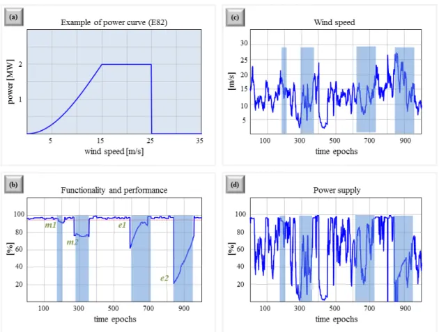
The main task of an OWF as a component of the transnational power supply system is the reliable provision of wind energy in compliance to its specification. Due to the variation of wind strength it can be expected that the power provided by a single windmill will vary between zero and the nominal power (design criteria). Like seen, wind speeds between 15 and 25 m/s are needed to meet the nominal power supply of 2 MW (Fig. 1a). The number of deployed windmills (e.g. 150) determines the nominal power of the OFW (e.g. 300 MW). If a margin would be foreseen in OFW design (more than 150 windmills) two things are enabled: On the one hand, the nominal power of OWF can be supported at lower wind speeds, if all windmills are in operation. On the other hand planned maintenance activities (m1) as well as small-scale failures (e1) cannot significantly disrupt the energy delivery by the OWF. However, additional repair and restoration measures are needed for the recovery of original OWF functionality and performance, if non-compensable failures (e2) have been occurred. Our example shown in Figure 1 also illustrates that the measurement of power supply is inadequate to indicate the
current resilience level of OWF.
If resilience is related explicitly to OWF functionality and performance, Figure 1b depicts the resilience behavior of the exemplarily OWF over time. The aim of resilience-enhancing measures is the retaining of functionality and performance as close as possible at 100%. Proactive measures are intended to avoid destructive events, to reduce their frequency, or to limit demolitions. A representative example is the use of condition monitoring to achieve an efficient and effective scheduling of maintenance and repair to ensure a reliable OWF operation within its system boundaries.
Figure 1 Illustrated example of influences on OWF power supply
Proactive measures may also ensure a kind of “preparedness” in relation to unpredictable and unavoidable destructive events. Measures in this context are the provision of means needed for fire protection as well as the holding of resources for a quick repair in emergency cases. The actual realization of measures for damage containment, recovery and restoration are reactive by nature. They are induced in response to occurred destructions and done decisions. Enhanced resilience concepts consider, besides robust operation and capability for rebounding, also approaches to ensure a reliable operation nearby system boundaries (avoidance of cascade effects) and to maintain a sustained adaptability especially in relation to emerging threat situations (maintain flexibility to changes) [6]. A challenge in this context is the protection of the cyberspace for critical infrastructures such as OWF.
There have already been examples of resilient as well non-resilient wind farm operation from experience. On 22.09.2009 there was a fault at the onshore substation of West Wind OWF near Wellington, New Zealand. A transformer had a circuit-breaker failure that resulted in a serious fire and fire service callout. A dip to 80% voltage, beneath the operational thresholds (under voltage), was seen on all three phases on the 110 kV connections for 2.5s. In Wellington it was reported that fluorescent lights went out briefly though the produced power did dip zero. The fault was cleared by the circuit breaker failure protection system within approximately 2.5 s. Immediately on fault clearance, the 110 kV voltage spiked up to 119 kV (over voltage), which triggered a fault ride-through reaction by the OWF control system by increasing the reactive power so that the voltage restored its normal operational value of 110 kV. The quick recovery of power supply and the behavior West Wind OWF in general on this occasion can be regarded as resilient [4] and this behavior corresponds to event (e1) in Figure 1.
In contrast to that the big blackout on 04.11.2006 interrupted the power supply of more than 15 million households across Europe [7, 8]. Wind power generation was named as the main influence factor and this can be classified as a non-resilient behavior of OWF. At the time wind generation units were automatically disconnected by their protection systems from the power grid if the frequency of the grid dropped below the threshold of 49.5 Hz. In the Western area of the grid the frequency was 49 Hz immediately after the disturbance. As a consequence 60 % of the wind power was disconnected in an uncontrolled way which exacerbated the frequency drop in the Western area. Therefore this behavior can be related to the event (e2) in Figure 1. Scope of this paper is the investigation of disturbances due to possible cyber-physical attacks on an OWF and the resulting response to them in relation to OWF resilience.
For this purpose in chapter 2 a functional model of a generic OWF is introduced to represent the OWF operation, functionality and performance. It is an interconnected and multi-layered model demonstrating the main functional processes and the dependences/interactions between them, covering safety and security aspects, too. The model is the basis for the analysis in Chapter 4 since the model components are presented explicitly with their functions and the corresponding I/O parameters, signals and data.
Chapter 3 discusses the IT infrastructure within the OWF, its control system networks and the design of the implemented controllers. Documented in the literature vulnerabilities of the OWF to cyber-physical attacks are reviewed and the resulting from them possibility for malicious manipulation of main functional processes.
In Chapter 4 an analysis of the disturbances arising from specific cyber-physical attacks is given based on the functional model from Chapter 2. This includes the identification of the corresponding risk elements, the manipulated parameters, signals and thresholds as well as the resulting chains of effect. Alongside with this an evaluation of the impact of these disturbances is performed in relation to the resilience OWF, besides with risk assessment. In Chapter 5 a proposal is made for resilience-enhancing measures against these attacks. The measures are on component and functional level regarding both the proactive and the reactive aspect.
In the final Chapter 6 we present initial conclusions and give an outlook for our future work.
2. FUNCTIONAL SYSTEM MODEL AND RESILIENCE DEGREES OF A GENERIC OWF
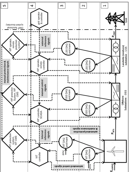
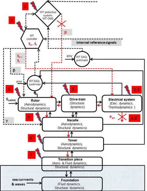
A functional model describes the technical behavior of engineered, cyber-physical systems in relation to the intended task or results of the system. It is a representation of the operation, functionality and performance of the system, e.g. in the form of a block diagram. The model represents the interaction of energy, matter and information needed for the system functionality, too. The block diagram consists of components performing, according to their technical characteristics, specified functions on the inputs. The inputs are parameters corresponding to flows of energy, matter, signals and data. The respective outputs are functions of the inputs under consideration of the internal/environmental conditions and other influencing factors. Applied to the OWF the components can be grouped into several layers representing the main functional processes as pictured and numbered, in Figure 2.
The first layer corresponds to the conversion of energy. Within this layer the kinetic energy of
voltage of this energy is increased by the offshore and the landside substations so that the overall
electrical energy POWF is fed into the grid as an output from the OWF. In the second layer data
is acquired which is needed for the control and monitoring within the OWF. The measurements of the internal operational and the environmental conditions are done here and then transferred to the fourth layer. In third layer the corresponding data needed for the protection and maintenance is acquired and passed to the fifth layer in an analogous way.
Figure 2. Functional model of a generic OWF. Solid arrows are flows of energy/matter, dashed lines flows of signals/data. DAQ: data acquisition; contr/mon: control and monitoring; prot/maint: protection and maintenance; Ek, WIND: kinetic energy of the wind;
PWTs: electrical energy from the wind turbines; POWF: electrical energy from the wind farm;
env: influence of the environmental conditions; SCADA: supervisory control and data acquisition system; CMS: condition monitoring system; CC: control center
In the fourth layer the control and monitoring of the operation and performance is executed within the OWF. The layer controls the conversion of energy and the feed of this energy into
the grid through automated control signals. This layer also monitors the thresholds in the related data. The normal operation mode of the OWF is a fully automated operation mode executed by the control systems within this layer based on the data from the data acquisition systems, its analysis and the internal/external reference signals. Manual operation through manual control signals is restricted to switching on and off of the WTs/OWF from the remote control center of the WF operator.
The normal operational mode is present when all operational parameters and external conditions are within their thresholds, and when there is no interruption of signal or data flow. A disturbed operation occurs when the operational parameters are driven beyond the thresholds due to some component malfunction, failures, breakdowns, interruption of the data/signal flow or when the external conditions become outside of the specifications.
The last fifth layer refers to the protection (safety/security) and maintenance. The layer protects the functionality and the structural integrity within the OWF by disturbed conditions. Respective safety/security measures are initiated through automated or manual protection signals. Concerning the wind turbines these measures are a shut-down or a fast shut-down procedure by an increase of the rotor blade angle by the protection system. According to the assessment of the system condition by the condition monitoring system (CMS) automatic maintenance signals are generated for execution of maintenance. Maintenance can be initiated through manual signals from the remote control center of the WF operator, too.
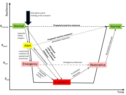
The general relation between the resilience and the resilience-enhancing measures was discussed in Chapter 1. There is also a relation between the resilience of a power generating system, its system states and the implemented measures (actions) for prevention, emergency and restoration [9, 10]. Adapted from [10] to the generic OWF the conceptual curve describing this relation is shown in Figure 3.
Figure 3. Conceptual resilience curve relating resilience, system states and measures of a generic OWF
The expected impacts from cyber-physical attacks discussed in this paper are added to the original curve in [10] as triggers for the transitions between system states next to these from the disturbances. The measures proposed by us are added to the curve, too.
Principally there are 5 possible operating states of the power generating system - based on the safety/security margins – normal, alert, emergency, in extremis (collapse) and restorative. A different degree of resilience is assigned to these states so that they can be regarded as states of resilience [9, 10]. So the resilience curve in Figure 3 maps the system states to the concept of resilience. The transitions between these states are initiated by disruptive events or by actions of the control/protection systems. So the transitions depend on the severity (impact) of the disturbance and on the effectiveness of the preventive and corrective control actions.
The normal operation state corresponds to the highest degree of resilience Rnormal. Within this
system state all operational thresholds are fulfilled and the safety (security) margins are adequate. A disruptive event leads initially to a violation of the margins, causing a transition to
the alert state with a reduced degree of resilience Ralert. If preventive measures, restoring the
normal state, are not undertaken a violation of the operational thresholds, i.e. disturbance, follows bringing the system to an emergency state with a further decreased resilience degree
Rem. Emergency actions could bring the system to the restorative state, preserving the degree of
resilience and preventing the system from transitioning to the in extremis state with the lowest
possible resilience level Rext. However, a highly severe disturbance with a significant violation
of the thresholds would lead the system directly to the in extremis state. The expected impacts from the cyber-physical attacks discussed in this paper correspond exactly to such disturbances However, the recovery time from these impacts would be much longer than the impacts of the usual disturbances (with no recovery from compared to the usual disturbances). Such a behavior and the corresponding resilience curve are termed as non-resilient [11]. Therefore we propose proactive and reactive measure to avoid such events. Our reactive measures correspond to the preventive actions depicted in Figure 3. Our proactive measures would preserve the normal operation state with no decrease of the resilience degree.
3. VULNERABILITY OF THE OWF TO CYBER-PHYSICAL ATTACKS
Cyber-physical attack (CPA) on physical systems aims at causing physical damages to the system through the IT environment. It differs from known viruses and malicious software, because it does not only affect the IT-system itself but also tries to cause physical damages. A major power outage due to a cyber attack on the control systems affecting about 220 000 customers occurred on 23.12.2015 in the Ukraine [12]. By the CPA the starting point is exploiting some physical security weaknesses within the infrastructure (e.g. by a single WT, OSS, LSS, WF operator remote center) or the supply chain. The relatively light physical access to the infrastructures in hardly accessible sea regions in the case of OWF, which per se are difficult to control, makes the CPA possible. Through a physical security weakness malicious software is infiltrated within the communication systems of the infrastructure. This is made easier since cyber security requirements are usually not fulfilled within the OWF.
The vulnerability of the wind farms to cyber-physical attacks has been demonstrated in the literature [13]. Several specific reasons were given for this vulnerability besides the above
mentioned. Traditionally the control networks (SCADA) are unrestricted and use rather
insecure SCADA protocols, such as OPC. The OPC protocol is used for the exchange of the real-time data, monitoring of alarms and events, and the setting and update of control parameter values. The protocol does not include any authentication or encryption.
The controllers used within the wind farm are PLC (programmable logic controllers) and PAC (programmable automation controllers). The PACs run legacy operating systems. They are logged within the control networks in root mode – gaining access by a CPA to one (WT) controller gives an access to whole network. They are IP-addressable and so online reprogrammable. There is no authentication or encryption of the control/protection signals as well. Critical control and protection parameters or thresholds can be modified by accessing the controller Object Dictionaries and injecting corresponding Shared Data Object messages. For the purpose the layout of the Object Dictionary must be known, which is defined in the vendor Electronic Data Sheet.
Thus the main functional processes are principally accessible to malicious manipulation as a consequence by manipulation of the corresponding operational parameters and thresholds, signals and data.
4. IMPACTS OF CYBER-PHYSICAL ATTACKS ON THE OWF
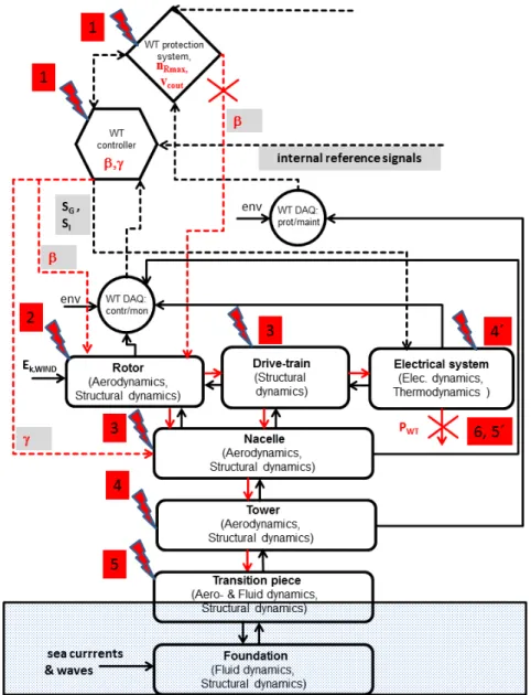
Based on the functional model in Chapter 2 we identify risk components with their functions and the corresponding chains of effect (propagation of the disturbance initiated by the manipulation) within the OWF regarding the scenarios of cyber-physical attacks discussed in the previous chapter. For the purpose we have developed a full functional model of the WT and the corresponding structures in a way analogous to mechatronics, consisting of the relevant cyber-physical systems. The cyber systems concern the WT operation (data acquisition, control and protection) as already discussed in Chapter 2. The structures are modelled as physical systems characterized by the dynamics from the respective domains. The model shows the couplings between all the systems explicitly. Therefore it is a detailed WT section in the block diagram in Figure. 2.
We present two main scenarios. The first scenario concerns the manipulation of the control signals and thresholds of operational parameters in the mechanical control system of a single wind turbine. The chains of effect are pictured in Figure 4. By the first step (1) the WT controller
is affected so that a value of the rotor blade angle β = β MIN is prescribed and the nacelle angle
γ is kept fixed along the wind direction. The control signals of the electrical control system to
generator (SG) and the invertor (SI) are not affected by this scenario.
Alongside with this the thresholds of the rotor speed nRmax and the cut-out wind speed vcout must
be manipulated in the protection system, either removed or excessively increased. Due to the levering out of the protection system the WT cannot be secured by a (fast) shut-down procedure
since the rotor blade angle is kept at β = β MIN and no protective signal is sent for its increase.
The consequence would be an excessive rotor speeds under normal wind conditions, step (2). These would cause excessive mechanical overloads result at step (3), affecting the drive-train and the nacelle. These excessive overloads would propagate to the tower and the transition piece at step (4) and (5), respectively. Excessive damage and even destruction of the main components is imminent and the destruction of the structures (nacelle, tower, transition piece)
is possible, accompanied by loss of performance PWT of the WT (6). Another branch of the
chain of effect is the propagation of the excessive overloads to the electrical system, step (4´).
This would disrupt its functionality leading to the loss of performance PWT of the WT (5´), too.
Applied to all wind turbines this scenario would affect the whole wind farm corresponding to a system collapse (in extremis state) with downtimes by at least a magnitude greater than the recovery times from the usual disturbances due to usual component failures. The usual WT
component failures result in approx. 400-450 hours downtime. In contrast the above scenario would cause either a damage of a single main component with approx. 1500-2700 hours downtime or the destruction of the structures demanding even bigger downtimes.
Figure 4. Chains of effect by scenario 1
The second scenario concerns the manipulation of the control signals in electrical WT control system. The corresponding chain of effect is depicted in Figure 5. Initially the controller is
affected (1) by manipulation of the control signals SG and SI, e.g. by repetitive step changes
leading to voltage sags. Alongside with this the protection system can be levered out, e.g just by fixing the value of β so that no protection signal is sent for securing the WT by shut-down procedure when thermal or vibration thresholds are exceeded. The effect would be electrical disturbances at the converter and the invertor at normal grid conditions (2). These disturbances are characterized by large excursions of the resulting transient currents associated with overvoltage, very dangerous to the power electronics [3]. Thus excessive thermal overloads (3) can be realized at the converter and the invertor. Extreme damages of the power electronics
alongside with a fire threat are so possible, accompanied by loss of performance PWT of the WT
(4). Due to the fire threat the destruction of these components or of the WT is possible, too. Another branch of the chain of effect is realized due the coupling of the electrical system to the drive-train. Thus the disturbances in the electrical system would excite abnormal additional vibrations in the drive-train (3´), propagating to the rotor (4´), nacelle (5´), the tower (6´) and the transition piece (7´).
Figure 5. Chains of effect by scenario 2
Normal vibrations within the operational specifications are excited by the wind though the aerodynamics of the rotor blades, the nacelle and the nacelle. However the additional vibrations due to the electrical disturbances may superimpose the normal ones so that severe overall vibrations can arise with abnormal amplitudes and frequencies [14, 15] disrupting the
performance PWT of the WT (8´). Again, applied to all WT within the wind farm this scenario
would cause a system collapse (in extremis state) by magnitudes greater downtimes compared to the usual electrical disturbances.
5. MEASURES AGAINST CYBER-PHYSICAL ATTACKS
Measures to prevent the cyber-physical attacks described in the previous chapter must take all aspects of the development and impact of the attacks into account. Therefore both proactive
and reactive measures have to be considered,on component level as well as on functional level.
Since most modern WTs are pitch-controlled and pitch-secured through the rotor blade angle a special attention must be payed to the related signals. Both the control and protection signals must be inaccessible to modification simply with Shared Data Object messages. This demands software changes in the layout of the controller Object Dictionaries and in the OPC protocols (read-only). The same should apply to other crucial control/protection signals (e.g. nacelle angle, generator and invertor control signal) with the corresponding thresholds (e.g. rotor speed and the cut-out wind speed) as proactive measures. Besides the physical and the cyber security within the OWF must be generally increased proactively, e.g. through motion sensors/CCTV and through authentication/encryption of the OPC protocols. Physical access to all terminals, SCADA computers, maintenance interfaces must be strictly controlled through access restriction, too (e.g. digitally controlled doors, locks, access permissions, etc.). All these measures are illustrated by the proposed proactive measures in Figure. 3.
Various reactive measures must be employed based on real-time techniques within the OWF. The reactive measures refer both to the detection of as well as to the response the OWF to an ongoing attack. Real-time monitoring and analysis is demanded for the detection of the attack. Plausibility (consistency) tests of the current parameter values and their thresholds through analysis of the real time would data allow the detection of deviation from the normal operation state caused by attacks as described in Chapter 4. Monitoring and analysis of the network traffic between and within the layers of the functional model would allow the detection of suspicious communication structures and traffic rates. Reference Technology Systems (RTS) simulate with a physical functional model the real system state in real time. Deviations between real behavior and model indicate abnormal activities. After detecting an attack response measures must be undertaken. These include, for example strategies for setting normal operation values of parameters/thresholds. Other measures would include the fast and safe shutdown of the OWP, the definition of recovery points and a strategy to reset to these recovery points with quick resumption of plant operation.
6. CONCLUSIONS AND OUTLOOK
We have developed a functional system model of the OWF. Through the model we have investigated the impacts of specific cyber-physical attacks on the OWF. The impacts can affect the OWF functionality and performance extremely and its behavior is clearly non-resilient thereby. The power grid can be severely affected, too. So major security gaps definitely exist concerning the OWF vulnerability to cyber-physical attacks. We have proposed therefore proactive and reactive measures for closing the above gaps which we can evaluate as plausible in qualitative terms based on the proposed functional model.
The outlook for our future work includes the test of the described measures in hardware-in-the-loop constellations. This would enable a numerical instead of a qualitative evaluation of the proposed measures. Besides this we want to develop a numerical model of the OWF based on the functional model presented here. This model would allow us to study the disturbances discussed here in quantitative terms.
REFERENCES
[1] https://www.wind-energie.de/themen/zahlen-und-fakten/
[2] Thomas Ackermann, ed., Wind power in power systems, 2012, John Wiley & Sons Ltd, ISBN 978-0-470-97416-2
[3] Schaffarczyk, Alois, Understanding wind power technology : theory, deployment and optimisation, 2014, John Wiley & Sons, Ltd
[4] United Nations Office for Disaster Risk Reduction (UNISDR): UNISDR terminology on
disaster risk reduction, 2009, Genueva, available from
http://www.unisdr.org/files/7817_UNISDRTerminologyEnglish.pdf
[5] International Maritime Organization (IMO): GUIDELINES FOR SHIPBORNE
POSITION, NAVIGATION AND TIMING (PNT)DATA PROCESSING, MSC.1/Circ.1575, 16 June 2017
[6] Woods DD. Four concepts for resilience and the implications for the future of resilience engineering. Reliability Engineering and System Safety (2015), 141, 5-9.
http://doi.org/10.1016/j.ress.2015.03.018
[7] Federal Network Agency for Electricity, Gas, Telecommunications, Post and Railways,
Report on the disturbance in the German and European power system on the 4th of November 2006,
https://www.bundesnetzagentur.de/SharedDocs/Downloads/EN/Areas/ElectricityGas/Special %20Topics/Blackout2005/BerichtEnglischeVersionId9347pdf.pdf?__blob=publicationFile&v =4
[8] UCTE, Final Report - System Disturbance on 4 November 2006,
https://www.entsoe.eu/fileadmin/user_upload/_library/publications/ce/otherreports/Final-Report-20070130.pdf
[9] Erik Hollnagel, David D. Woods and Nancy Leveson, Resilience engineering : concepts
and precepts, Ashgate, ISBN 0-7546-4641-6
[10] Mathaios Panteli and Pierluigi Mancarella, Modeling and Evaluating the Resilience of Critical Electrical Power Infrastructure to Extreme Weather Events, IEEE SYSTEMS JOURNAL, VOL. 11, NO. 3, SEPTEMBER 2017
[11] Häring, I., Ebenhöch, S. & Stolz, A., Quantifying Resilience for Resilience Engineering
of Socio Technical Systems, Eur J Secur Res (2016) 1: 21.
https://doi.org/10.1007/s41125-015-0001-x
[12] National Cybersecurity and Communications Integration Center, Cyber-Attack Against
Ukrainian Critical Infrastructure, https://ics-cert.us-cert.gov/alerts/IR-ALERT-H-16-056-01
[13] J. Staggs, D. Ferlemann, S. Shenoi, Wind farm security: attack surface, targets,
scenarios and mitigation, International Journal of Critical Infrastructure Protection, 17, 2017,
3-14, ISSN 1874-5482, https://doi.org/10.1016/j.ijcip.2017.03.001
[14] Fadaeinedjad R, Moschopoulos G, Moallem M., Investigation of voltage sag impact on
wind turbine tower vibrations. Wind Energy 2008; 11: 351–375. DOI: 10.1002/we.266.
[15] Link, M., Weiland, M., Monitoring der Monopile-Gründung einer Offshore
Windkraftanlage im EnBW Windpark Baltic 1, 5. Fachtagung Baudynamik 2015,