2012:42
Technical Note
Initial review of physical properties and
processes of the buffer and backfi ll
– Installation and initial state
SSM perspektiv
BakgrundStrålsäkerhetsmyndigheten (SSM) granskar Svensk Kärnbränslehantering
AB:s (SKB) ansökningar enligt lagen (1984:3) om kärnteknisk verksamhet om
uppförande, innehav och drift av ett slutförvar för använt kärnbränsle och
av en inkapslingsanläggning. Som en del i granskningen ger SSM konsulter
uppdrag för att inhämta information i avgränsade frågor. I SSM:s Technical
note-serie rapporteras resultaten från dessa konsultuppdrag.
Projektets syfte
Denna rapport består av en ”Technical Note” inom SSM:s inledande
gransk-ning av SKB:s säkerhetsredovisgransk-ning SR-Site. Syftet med denna inledande
granskning av frågorna kring installation och initialtillstånd av buffert och
återfyllnad i slutförvarsanläggningen är att få en bred granskning och
belys-ning av SR-Site med underreferenser samt att identifiera eventuella behov
av kompletterande information eller förtydliganden som SKB bör tillfoga
ansökansunderlaget.
Författarens sammanfattning
Denna rapport ger en sammanfattning av de konstruktionsförutsättningar
och funktioner av bufferten och återfyllnaden som SKB föreslagit, samt
utvärderar SKB:s arbete med tillverkning, installation och prövning av de
föreslagna metoderna.
Sammanfattningsvis har denna granskning identifierat flera procedurer och
praktiska tekniska aspekter (t.ex. kvalitetssäkringsprocedurer,
återfyllnings-hastighet) samt några fysikaliska processer i bufferten och återfyllnaden,
som behöver ytterligare forsknings- och utvecklingsinsatser – mer detaljerad
granskning av dessa områden har föreslagits. SSM bör också tänka på mer
detaljerad granskning av huruvida egenskaperna och utvecklingen av
buffer-ten och återfyllnaden representeras på ett rätt sätt i säkerhetsanalysen.
ProjektinformationKontaktperson på SSM:
Diarienummer ramavtal: SSM2010-4230
Diarienummer avrop: SSM2011-4206
Aktivitetsnummer: 3030007-4007
SSM perspective
BackgroundThe Swedish Radiation Safety Authority (SSM) reviews the Swedish
Nu-clear Fuel Company’s (SKB) applications under the Act on NuNu-clear
Acti-vities (SFS 1984:3) for the construction and operation of a repository for
spent nuclear fuel and for an encapsulation facility. As part of the review,
SSM commissions consultants to carry out work in order to obtain
in-formation on specific issues. The results from the consultants’ tasks are
reported in SSM’s Technical Note series.
Objectives of the project
This report consists of a Technical Note in SSM’s initial review phase of
SKB’s safety analysis SR-Site. The aim of the initial review of issues
concer-ning installation and initial state of buffer and backfill in a final
reposi-tory is to make a broad illustration and review of SR-Site together with its
subordinate references, as well as to identify potential needs for
comple-mentary information or clarification which SKB should supplement to its
license applications.
Summary by the author
The technical note briefly summarises the proposed designs and
fun-ctions of the buffer and backfill, and examines SKB’s progress in
manufac-turing, installing and testing its proposed solutions.
In brief, the review suggests that there are some procedural and practical
engineering aspects (e.g., quality assurance procedures, backfilling rates)
and several physical processes to do with the buffer and backfill materials
on which further research and development will be needed – more
de-tailed review of these areas is suggested. SSM should also consider more
detailed review of whether the properties and behaviour of the buffer and
backfill are properly represented in the safety assessment.
Project information
2012:42
Author:
Initial review of physical properties and
processes of the buffer and backfill
– Installation and initial state
David G. Bennett
TerraSalus Ltd., Oakham, U. K.
This report was commissioned by the Swedish Radiation Safety Authority
(SSM). The conclusions and viewpoints presented in the report are those
of the author(s) and do not necessarily coincide with those of SSM.
Summary
The Swedish Radiation Safety Authority (SSM) is reviewing a license application, which has been submitted by Svensk Kärnbränslehantering AB (SKB), for a spent nuclear fuel repository.
This technical note records the findings from a project that forms part of SSM’s initial phase of the license application review. The project was undertaken on behalf of SSM by TerraSalus Limited.
The project involved review of SKB’s reports on issues related to the installation and initial state of the bentonite clay buffer and backfill materials that SKB proposes to use to fill the spaces in the repository around the spent fuel canisters.
The technical note briefly summarises the proposed designs and functions of the buffer and backfill, and examines SKB’s progress in manufacturing, installing and testing its proposed solutions.
In brief, the review suggests that there are some procedural and practical engineering aspects (e.g., quality assurance procedures, backfilling rates) and several physical processes to do with the buffer and backfill materials on which further research and development will be needed – more detailed review of these areas is suggested. SSM should also consider more detailed review of whether the properties and behaviour of the buffer and backfill are properly represented in the safety assessment.
On the basis of the information reviewed, the note identifies various questions that might be asked of SKB as part of the next phase of the license application review. The note also identifies areas in which SSM may conduct more detailed review.
Content
1. Introduction ... 5
2. Main review findings ... 7
2.1. Definition of Initial State ... 7
2.2. Buffer ... 7
2.2.1. Design ... 7
2.2.2. Safety Functions ... 8
2.2.3. Materials ... 9
2.2.4. Manufacture, Handling & Installation ... 9
2.2.5. Properties ... 12
2.3. Backfill ... 13
2.3.1. Design ... 13
2.3.2. Safety Functions ... 14
2.3.3. Materials ... 14
2.3.4. Manufacture, Handling & Installation ... 15
2.3.5. Properties ... 16
2.4. Key Processes and Issues ... 17
2.4.1. Re-saturation and the thermal phase ... 17
2.4.2. Hydro-mechanical effects ... 18
2.4.3. Quantifying erosion and buffer and backfill mass loss ... 21
2.4.4. Backfill emplacement rate... 23
2.5. Safety Assessment ... 24
2.6. Conclusions ... 25
3. Recommendations to SSM ... 27
1. Introduction
The Swedish Radiation Safety Authority (SSM) is undertaking a formal review of a License Application, which has been submitted by Svensk Kärnbränslehantering AB (SKB) for construction, possession and operation of a spent nuclear fuel repository in Forsmark. SKB’s Application includes a safety assessment known as SR-Site.
This technical note records the findings from a project that has been undertaken by TerraSalus Limited on behalf of SSM as part of its initial phase of review of the License Application.
The overall goal of SSM’s Initial Review Phase is to conduct a broad-ranging examination of SR-Site and its supporting references and, in particular, to identify the need for complementary information and clarifications to be provided by SKB and possible focuses for more in-depth review by SSM.
The project described in this technical note involved review of SKB’s reports on issues related to installation and achievement of the initial state of the bentonite buffer in deposition holes and the backfill material in deposition tunnels.
The installation and initial state issues considered included the following: material property characterization, fabrication, transportation and storage, emplacement, and other installation and initial state issues described in SKB’s reporting. In addition, the review considered the initial physical erosion of the buffer and backfill
materials, the so-called “piping and erosion” processes. However, chemical erosion processes that may affect the buffer and backfill when they come into contact with dilute groundwater were not included in this review project.
After the Initial Review Phase has been completed, SSM will determine if the quality and comprehensiveness of SR-Site is sufficiently good to warrant a further phase of in-depth review of the Licence Application - the ‘Main Review Phase’. It is envisaged that the Main Review Phase will focus on uncertain and/or safety critical issues that require more comprehensive review.
The remainder of this technical note is structured as follows:
Section 2 presents the main review findings.
Section 3 presents recommendations to SSM.
Appendix 1 identifies SKB reports that were reviewed or examined.
Appendix 2 provides a list of suggested questions to SKB for clarifications, complementary information, complementary data, etc.
Appendix 3 provides a list of suggested topics requiring substantial additional work on the part of SSM and SSM’s external experts during the Main Review Phase.
2. Main review findings
2.1. Definition of Initial State
In SR-Site, SKB defines the initial state as being the state at the time of deposition / installation for the engineered barrier system and the natural, undisturbed state at the time of beginning of excavation of the repository for the geosphere and biosphere (TR-11-01, page 19). This definition is clear and comprehensible, but precedes the time at which the repository and its components will be providing their safety functions. For example, the initial state is not defined as the time when the buffer becomes fully saturated with water and is therefore able to provide its main safety function of preventing water flow around the canister (TR-11-01, page 21).
As the scope of this review task includes consideration of the initial physical erosion of the buffer and backfill by piping and erosion processes, it necessarily extends beyond SKB’s definition of the initial state into the subsequent period during which buffer and backfill saturation may occur.
The point in time at which the barriers begin to fulfil their safety functions might have provided a logical alternative definition of the initial state. In any case, it is important for SKB’s analysis and for SSM’s review to cover the entire period including repository construction, operation, closure and long-term safety.
2.2. Buffer
2.2.1. Design
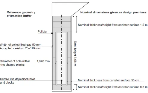
A vertical cross-section through the reference design for the buffer is illustrated in Figure 2.1. The buffer comprises a set of discs and rings of compressed bentonite that will surround the spent fuel canister. At the time of installation there would be a narrow gap between the canister and the inner surface of the buffer rings. The gap between the rock and the outer surface of the buffer rings would be filled with pellets made of compressed bentonite. The gaps should be closed by swelling of the bentonite as it becomes saturated with water.
A so called ‘bottom plate’ of copper on a thin concrete base would be used to provide a flat and level base at the bottom of the deposition hole on which to place the bentonite rings (Figure 2.2). At the top of the deposition hole is a bevel (the sloping area at the top of Figure 2.1), and the buffer interfaces with the overlying backfill. A so called ‘gamma gate’ would also be used at the top of the deposition hole to provide radiological shielding during repository operations.
Figure 2.1 Reference geometry of the buffer (from TR-10-15)
Figure 2.2 Illustration of the bottom of the deposition hole showing the concrete base and copper bottom plate (from TR-10-15).
2.2.2. Safety Functions
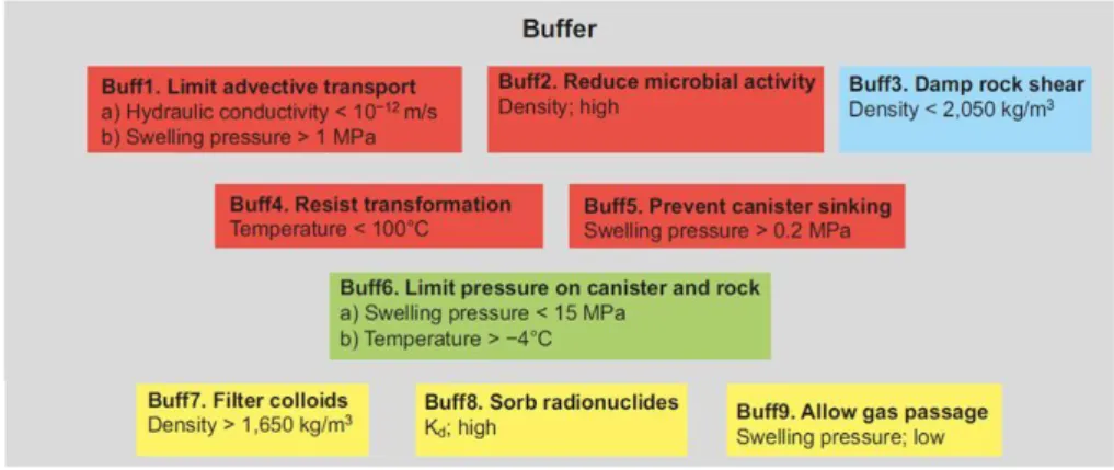
The safety functions defined by SKB for the buffer are shown in Figure 2.3. The defined safety functions of the buffer are to:
Limit advective transport of radionuclides in the region around the canister.
Reduce microbial activity near the canister.
Protect the canister in a mechanical sense by damping rock shear (e.g. associated with movement on rock fractures during earthquakes).
Resist mineral transformation (e.g., smectite to illite conversion).
Prevent canister sinking.
Limit the pressure on the canister and surrounding rock.
Filter colloids.
Allow the passage of gas.
Figure 2.3 indicates further details of the properties that the buffer material should, according to SKB, possess (e.g., densities, hydraulic conductivities, swelling pressures) once it has reached full saturation in order to fulfil these safety functions.
Figure 2.3 SKB’s buffer safety functions (from TR-11-01)
2.2.3. Materials
SKB indicates that the various buffer safety functions could be fulfilled by using commercially available bentonite clay-based buffer materials containing between 75% and 90 % montmorillonite and containing less than certain levels of impurities (organic carbon, sulphide). SKB has not specified in SR-Site which particular buffer materials would be used, preferring instead to retain flexibility in terms of materials suppliers.
Two example buffer materials are considered in SR-Site, a sodium-rich MX-80 bentonite and a calcium-rich bentonite called Ibeco RWC (this was called Deponit CA-N in SKB’s previous SR-Can safety report – TR-06-09). More details on potential buffer materials are given in TR-10-60.
2.2.4. Manufacture, Handling & Installation
Buffer block manufacture involves various drying and wetting processes to control the water content of the bentonite materials followed by the use of large uni-axial hydraulic presses (Figure 2.4) to compact the bentonite into ring and disc-shaped moulds. The blocks removed from the moulds are then machined to specified dimensions within specified tolerances. Details are provided in TR-10-15.
Figure 2.4 Pressing of a large buffer block (from TR-10-15)
SKB has successfully tested the manufacture of buffer rings with thicknesses of up to 500 mm, but is yet to test manufacturing of the thickest blocks and rings in the reference design, which are 800 mm thick (TR-10-15, page 64).
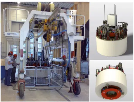
SKB has developed and tested special equipment for handling and installing the buffer blocks and rings in the deposition hole. This equipment involves a gantry crane system with vacuum block lifting equipment and additional physical support for the buffer blocks during hoisting operations after the blocks have initially been lifted (Figure 2.5). The installation system has been tested, but further testing at full scale will be required, including with arrangements in place for radiological
shielding.
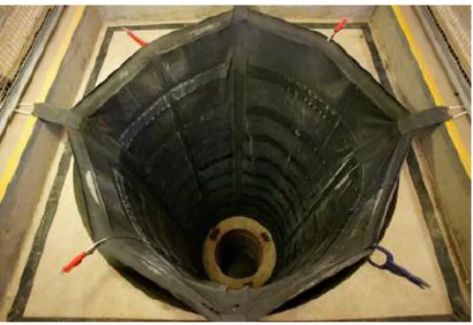
Recognising the potential for water to flow into the waste deposition holes during repository operation, SKB has designed and tested a system to protect installed buffer rings and blocks from water in the period prior to canister deposition. This system includes a rubber water protection sheet (Figure 2.6) that would be attached to the bottom plate as a temporary measure and a system of drainage tubes outside the rubber sheet that would be used to pump out any water entering the deposition hole before canister emplacement and completion of buffer installation.
Figure 2.6 Buffer water protection sheet (from TR-10-15)
In the past SSM’s external expert group BRITE (2010) has expressed concern concerning the design of the buffer water protection system and further testing should be considered to confirm the reliability of the procedures for the use and removal of the system.
Following removal of the buffer water protection system, bentonite pellets would be poured into the gap between the rock and the buffer blocks and rings. The
manufacture of the bentonite pellets involves a fairly standard and well-tested process of roller compaction of small briquettes.
In summary, the Production Report for the Buffer (TR-10-15) suggests that it should be feasible to manufacture and install the buffer components, but that more testing may be needed on:
Pressing 800 mm-high buffer rings.
Testing the buffer transport system at full scale.
Working with the design for the bottom plate, which is relatively new.
Working with the bevel and the gamma gate at the top of the deposition hole.
In addition, more detail than is presented in the Production Reports would be needed on the procedures and quality assurance measures to be used.
SKB has identified various opportunities for inspection of the buffer and backfill production, handling and installation processes (TR-10-15; TR-10-16), but an inspection plan is not yet developed in detail. It would be sensible for SSM to consider the strategy for monitoring and inspection of SKB’s programme and of facility implementation, including buffer and backfill manufacture and installation.
2.2.5. Properties
Key properties that relate to the buffer safety functions include the densities of the buffer materials that develop in the deposition hole, the swelling pressures developed and the hydraulic conductivities of the materials.
The buffer blocks and rings would be installed with an initial water content of 17%. The required buffer swelling pressure and hydraulic conductivity, however, will only be achieved after the buffer has fully re-saturated
Given the specified geometries and tolerances, the Buffer, Backfill and Closure Process Report (TR-10-47) suggests that it should in theory be possible to install the buffer and achieve the required buffer densities, based on consideration of the density - swelling pressure - hydraulic conductivity relationships which are well known (e.g. Figure 2.7). SKB has also undertaken various modelling studies to consider the effects on buffer density of the upwards swelling of the buffer into the region occupied by the backfill (see below).
Figure 2.7 Experimental data for MX-80 bentonite showing the relationships between buffer density, swelling pressure and hydraulic conductivity (from TR-10-15)
2.3. Backfill
2.3.1. Design
The reference design for the backfill is illustrated in Figure 2.8, and comprises a range of blocks, discs (for the top of the deposition hole) and pellets of compressed bentonite (but see Section 2.3.3 below) that would fill the tunnel space above the buffer in the deposition holes.
2.3.2. Safety Functions
The safety functions defined by SKB for the backfill are shown in Figure 2.9. The defined safety functions of the buffer are to:
Counteract buffer expansion.
Limit advective transport of radionuclides.
Sorb radionuclides.
Figure 2.9 SKB’s backfill safety functions (from TR-11-01)
Figure 2.9 indicates further details of the properties that the backfill material should possess (e.g., densities, hydraulic conductivities, swelling pressures) once it has reached full saturation in order to fulfil these safety functions.
2.3.3. Materials
The reference material for the backfill is also based on bentonite clay, but its composition is less tightly specified than for the buffer. SKB suggests that the reference composition should contain between 50 and 60 % montmorillonite, but that this range might in future be widened (relaxed) (TR-10-16).
The example backfill material considered in SR-Site is the calcium and magnesium-rich Milos BF 04 bentonite.
TR-10-16 (page 33) suggests that smectite-rich mixed layer clays or mixtures of bentonite and ballast might be used. This latter point should be checked with SKB because it seems not to take account of previous statements and experiments on such materials (e.g., see R-09-52, page 118: “All of the backfill block materials studied,
excluding the mixture of bentonite and ballast (30:70), are suitable candidates for backfilling using the block-pellet concept. The 30/70 mixture was excluded mainly due to its apparently limited self-sealing capacity but also due to low safety margin compared to other material alternatives”).
2.3.4. Manufacture, Handling & Installation
The reference method for manufacturing of backfill blocks is uniaxial compression of individual blocks; the pellets would be made with roller compaction. These are conventional methods which SKB has customised and tested to produce backfill components that conform to the reference design (TR-10-16).
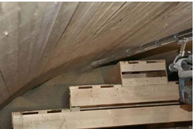
The backfill blocks would be transported to repository level on specially designed pallets. The pellets would be transported in containers. To achieve the prescribed installation rate, approximately 40 pallets of blocks and 15 containers of pellets would need to be transported underground daily.
The pallets with blocks and containers with pellets would initially be stored below ground in a central storage area. Results from R-08-59 suggest that it will be necessary to protect the backfill materials from water whilst they are in storage - details of the actual procedures to be followed are not provided in the Production Reports, however.
The blocks would subsequently be reloaded on to a transport vehicle that would deliver the blocks to the backfilling machine in the deposition tunnel. The pellets would be transported in their special containers to the deposition tunnel for subsequent installation.
Following installation of the buffer, the bevel at the top of the deposition hole would be backfilled apparently using a combination of discs, pellets and compacting machines (Figure 2.10) although this is not described in much detail in the text of TR-10-16.
Figure 2.10 Trials of backfilling the top of a deposition hole (from TR-10-16).
The reference method for installation of the bottom bed onto which the tunnel backfill blocks would be placed is to use a screw feeder and compaction equipment to compact the material. This is a relatively new method and may need further testing and development.
The reference method for installation of the backfill blocks is the “block method”, which would involve individual placement of each block with a block installer (Figure 2.11; TR-10-16).
Figure 2.11 Illustration of backfill block placement (from TR-10-16).
The reference method for installation of the pellets around the blocks is to inject the pellets with dry spraying equipment (Figure 2.12; TR-10-16).
Figure 2.12 Trial installation of backfill pellets (from TR-10-16).
In addition to more testing, more detail than is presented in the Production Reports would be needed on the procedures and quality assurance measures to be used.
2.3.5. Properties
The installed density of the backfill would depend on the volume of the tunnel (which would depend on the results of the blasting and the amount of overbreak or underbreak), and the mass of backfill emplaced (which would depend on the proportions of backfill blocks and pellets placed in the tunnel). All of these parameters will need to be measured during backfill emplacement to verify that the installed density conforms to the design requirements. These aspects are recognised in some of SKB’s reports (e.g. R-08-59), but again details of the actual procedures to be followed are not provided in the Production Reports.
At this stage, measurements that would allow the installed density of the backfill to be calculated are not available – instead scoping calculations are presented in TR-10-16. For a range of tunnel sizes, the scoping calculations give installed backfill densities between 1,458 and 1,535 kg/m3. These results suggest that the installed density of the backfill will be high enough to prevent too much upwards movement of the buffer and to provide the required swelling pressure and low hydraulic conductivity.
2.4. Key Processes and Issues
This section highlights several key process and issues that are potentially important for buffer and backfill installation and performance. The processes have been identified and studied during several experimental and modelling programmes that SKB has sponsored or contributed to, and these are referenced and discussed in the buffer and backfill process reports.
The key processes include: heat transfer, water inflow, buffer and backfill re-saturation and associated effects such as heave, piping, erosion, mass loss and material homogenisation.
2.4.1. Re-saturation and the thermal phase
The rate of water inflow to the deposition holes and tunnels will be a key factor affecting re-saturation and the thermal evolution of the buffer and backfill.
At Forsmark re-saturation processes may occur relatively slowly and may be spatially variable because the site hydrology is rather dry and there are few flowing fractures at repository depth (TR-11-01, pages 329 and 341).
Slow water inflows may lead to relatively long re-saturation times. SKB suggests that it may take from a few tens of years to a few thousand years for different parts of the repository to reach full saturation (TR-11-01, Section 10.3.8). The disposal system is designed so that peak temperatures in the buffer will be less than 100° C and the thermal peak is estimated to occur just ~5 to 15 years after canister
deposition (TR-11-01, page 325). According to these estimates, the “thermal phase” – the period with significantly elevated temperatures – may largely occur before re-saturation is complete. Near the canister where conditions are hottest and driest, the buffer may shrink and crack (TR-47-10, page 89).
If the thermal phase occurs before the hydraulic gradients associated with repository excavation have lessened, then there is the possibility of piping and erosion of buffer and backfill materials both during the thermal phase and afterwards. SKB has begun to investigate the re-saturation, piping, erosion and re-sealing (homogenisation) behaviour of certain bentonite materials in laboratory studies at room temperature (see SSM 2010:38), but there may be a gap in knowledge relating to these processes
in backfill and particularly buffer materials that have previously experienced heating and drying.
It may be sensible, therefore, to consider in more detail the potential implications of the spatial variability in repository temperatures and in buffer and backfill re-saturation times.
2.4.2. Hydro-mechanical effects
Recent experiments on buffer installation and the effects of water inflow (R-09-29, R-10-70) have highlighted various processes that may affect the properties of the bentonite based buffer materials.
Water inflow from the rocks at Forsmark is likely to be localised because flow occurs mainly through fractures or channels on fracture surfaces rather than through the pores of the rock. Localised water inflows may cause various effects, including:
Heterogeneous wetting and displacement of bentonite blocks and pellets.
Bentonite piping and erosion.
Heave and cracking of buffer blocks.
These processes have the potential to decrease the density of the buffer and, if they are not subsequently sealed during swelling and homogenisation, any gaps and cracks that form might serve as pathways for gas and water flow, and colloid and radionuclide transport.
R-09-29 reports on an experimental study of water inflow to the buffer using a full-scale model of the top of the buffer and deposition hole. After installation of the buffer rings and pellets, the effect of localised water inflow at different rates was studied. During the tests the pressure was monitored and it was possible to observe the wetting of the bentonite pellets through the transparent sides of the experimental apparatus. It was also possible to observe the behaviour of the uppermost bentonite ring and pellets. At the end of the experiments, the tests were dismantled and the conditions of the lower bentonite rings and pellets were observed.
The results showed that piping occurred in all of the tests and that the bentonite pellets had no ability to seal water pathways while there was a continuous inflow of water (Figure 2.13, R-09-29).
Figure 2.13 A channel formed by piping in the pellet-filled outer part of the buffer (from R-09-29).
Wetting of the pellets was spatially heterogeneous (Figure 2.14). Water tended to flow initially downwards, under the influence of gravity, but, following this initial effect, more of the flow was directed upwards through the pellet-filled region comprising the outer portion of the buffer, suggesting that in a repository, water entering a deposition hole from a fracture might move upwards through the pellet filled region and affect the overlying backfill.
Figure 2.14 Heterogeneous wetting of the pellet-filled outer part of the buffer. Almost intact pellets can be seen after 7 days of water inflow (from R-09-29).
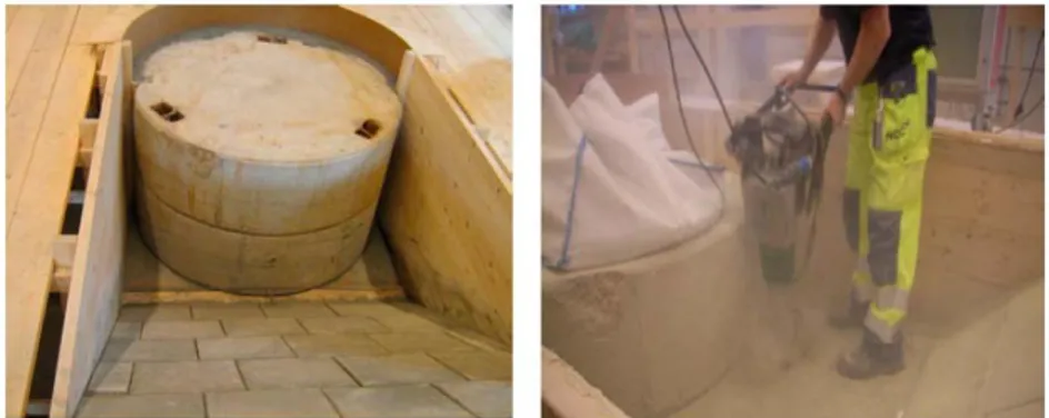
In another set of experiments, R-10-70 shows that under certain circumstances instead of absorbing water, hydrating and swelling, bentonite pellets can (like backfill blocks – see SSM 2010:38) be physically displaced by water pressure that builds up between them, leaving water-filled voids or gaps (Figure 2.15).
Figure 2.15 Photograph of bentonite pellets in a tube that have been displaced by water pressure (from R-10-70).
Significant heaving of the buffer rings was observed on a timescale of hours to days, particularly at the top of the experiment where there was an absence of overburden pressure (R-09-29). This aspect of the experiments very clearly demonstrates the need to install the backfill rapidly over the top of the buffer. Heave was also associated with significant cracking of the bentonite blocks.
Similar processes and effects were seen in a subsequent set of smaller-scale experiments reported in R-10-70 (Figures 2.16 and 2.17).
Figure 2.16 Heaving and cracking of MX-80 buffer rings, and partial wetting of MX-80 bentonite pellets after 3 months of inflow at 0.0001 litres/minute, equivalent to ~0.5 litres/year1
(from R-10-70).
Figure 2.17 Cracked MX-80 bentonite rings (from R-10-70). The figure on the right shows the result from a test involving hydration of MX-80 bentonite blocks and pellets at a low water inflow rate of 0.00001 litres/minute, equivalent to ~5 litres/year1. The buffer is seen to have
cracked in a radial fashion and the pellets have not hydrated uniformly (from R-10-70).
Backfilling tests and trials have shown that (see R-08-59 and SSM 2010:38):
The blocks need to be protected from water during storage, transport and installation.
Once installed, re-saturation can be localised and patchy.
Water often tends to flow through channels near the tunnel walls and can cause erosion and loss of backfill mass.
2.4.3. Quantifying erosion and buffer and backfill mass loss
Pages 83 and 84 of TR-10-47 present what SKB describes as a preliminary model for the mass of bentonite that may be eroded as a function of the mass (or total volume) of eroding water. The model was derived from short-term experimental data collected during the Baclo Project (R-08-135) and is defined by the following equation:
ms = β × (mw)α (2.1)
where:
ms = accumulated mass of eroded bentonite (g)
mw = accumulated mass of eroding water (g)
β = 0.02–2.0 α = 0.65
Figure 2.18 Empirical relationships between the total mass of eroded bentonite (grams) and total amount of eroding water (litres) in various short term erosion experiments. Also shown are model fits to the bounds of the data based on Equation 2.1 (from TR-10-47 and R-08-135).
TR-10-47 indicates that the model may be used for estimating the total amount of eroded buffer material in various situations, but that the model needs to be checked with additional tests, especially long term tests. TR-10-70 suggests a revision or update to the model to incorporate experimental data collected more recently and suggests that the range of β might be narrowed to between 0.02 and 0.2.
It seems that SKB is collecting data on bentonite erosion under various experimental circumstances and is still developing its empirical model to quantify the amounts of erosion that may occur. SKB describes the model as ‘preliminary’ and
acknowledges that the amounts of mass loss that may occur remain poorly quantified.
The piping-erosion model lacks an intuitively obvious theoretical
(phenomenological) basis; for example, as pointed out by SKB in TR-10-70, the calculated erosion rate does not depend on the rate of water flow. Figure 2.18 could be taken to imply that there is no lower value of flow rate below which piping and erosion would not occur. This, however, would not be consistent with SKB’s arguments that piping and erosion will probably stop once the hydraulic gradients associated with repository excavation have reduced, the deposition holes and tunnels have filled with water and swelling pressures have sealed the pipes (e.g. TR-10-47, page 81). The effectiveness of the hydraulic seal provided by the tunnel plug is a central aspect of SKB’s argument that piping and erosion will stop, and this should considered as a subject for further detailed review.
but this initial review has been unable to trace in detail how this has been done. Further detailed review is suggested to trace the basis for the quantities of tolerable mass loss.
2.4.4. Backfill emplacement rate
The experiments described in R-09-29 and R-10-70 clearly demonstrate the importance of installing the backfill rapidly after buffer installation to prevent significant upwards heave and cracking of buffer blocks (Figure 2.16).
SKB’s Production Report (TR-10-16) suggests that more work will be needed to demonstrate that the backfill can be emplaced in the repository satisfactorily, particularly at the rates that would be needed if SKB’s plan is to dispose of one spent fuel canister per day, as may be implied on page 70 of TR-10-16, which states,
‘The assessment after tests and studies is that the method [for backfill emplacement] is feasible but that it is dependent on advanced technology. The vacuum technique for lifting blocks needs to be tested more as well as the quality of the blocks in handling. In order to conform to the design premise to backfill a length corresponding to the average distance between deposition holes per day and considering the time consumption for other activities, the blocks have to be stacked within 60 seconds. In the tests this has been proven possible, but it presupposes that installation checking is frequently approved and that the water inflows do not affect the blocks until the pellets have been installed. In order to support the conclusions and verify the performance of the technology, further full scale tests with pressed bentonite blocks will be performed.’ 2
Backfill block placement needs to be accurate enough to avoid gaps of more than a few millimetres between the blocks; otherwise the possibility of water pressure forcing the blocks apart increases.
TR-11-01, page 43 states that ‘There possibly could be improvements in the backfill
design from an installation point of view but there does not seem to be a need to change the design to further improve its safety functions.’ This statement seems
rather weak in suggesting that there possibly could be improvements in the backfill design from an installation point of view – review of other SKB reports and experiments on backfilling (e.g. TR-10-16, R-08-59) make it clear that further development and review in this area is needed.
2 It is noted that TR-10-13 (pages 75-76) indicates total canister encapsulation rates
of no more than 150 canisters per year for the period 2023 to 2070, which may suggest that realistic disposal rates might be lower than one canister per day.
2.5. Safety Assessment
This section presents some preliminary observations regarding the relevance of the foregoing discussions to safety assessment. Thorough consideration of the
representation of the buffer and backfill in safety assessment was, however, beyond the scope of this initial review project.
The SR-Site safety assessment is predicated on the assumed initial state of the system. For example, SKB states ‘The initial state of the system is a fundamental
input to the assessment and needs thorough substantiation’ (TR-11-01, page 23). It
is important, therefore, to determine how sensitive the assessment is to the
assumptions made regarding the initial state, and to consider what tolerance there is for deviations from the conditions assumed at the initial state. For example, the statement on page 30 of TR-11-01 that the density of the backfill is sufficient in all the cases analysed in the reference evolution scenario leaves open the question of what would happen if the desired backfill density was not achieved.
TR-11-01, Section 10.2.4 describes buffer and backfill evolution, and recognises the key processes and the uncertainties noted above. TR-11-01, Section 10.3.8
summarises various Thermo-Hydro-Mechanical (THM) modelling studies (by Åkesson et al., 2010; TR-10-11), which include looking at re-saturation times and some aspects of buffer homogenisation. Some of these modelling studies confirm that spatial variations will remain in final buffer and backfill densities and swelling pressures, and that homogenisation will not be complete or perfect, even without considering the effects of cracks, piping and erosion and gap or void formation. These modelling studies probably should be the subject of more detailed review once SKB has subjected them to thorough quality assurance (TR-10-47, page 65, indicates that TR-10-11 is yet to undergo a documented factual- and quality review).
Finally, it is noted that Section 12 of TR-11-01 argues that early phase piping and erosion and upwards swelling of the buffer will be less important buffer density reduction mechanisms than chemical erosion and colloid release processes. This, however, depends on the magnitude of chemical erosion which is also uncertain.
Section 12 of TR-11-01 also argues that the effects of buffer erosion would be no worse than assessed in the buffer advection scenario. At this stage, however, insufficient review has been done to confirm this view.
The points raised in this section are instances where the results from more than one of SSM’s initial review projects need to be brought together in an integrated fashion in order to allow a more thorough, detailed evaluation of SR-Site during the Main Review Phase.
2.6. Conclusions
SKB has described reference designs for the buffer and backfill, and has identified their functions and required properties, but has not specified which particular buffer and backfill materials would be used, preferring instead to retain flexibility for the future in terms of the selection of materials and materials suppliers.
In SR-Site, SKB discusses one example backfill materials (Milos BF 04) and two examples buffer materials (MX-80 and Ibeco RWC) as ‘relevant illustrations’ of possible materials that could be used in the repository.
SKB’s Production Reports (TR-10-15 and TR-10-16) indicate that manufacture of the buffer and backfill blocks is feasible, but that more work will be needed to demonstrate that they can be emplaced in the repository satisfactorily. This is most relevant to the backfill because of the need to ensure accurate emplacement in the short time available.
In addition to more testing, more detail than is presented in the Production Reports would be needed on the procedures and quality assurance measures to be used.
In reality bentonite can be difficult to work with, particularly underground where it will come into contact with water. Various measures will be needed to protect the buffer and backfill materials from water during transport, storage and installation in the repository.
Buffer and backfill re-saturation is complex and hard to model in detail. Data on flow in partially-saturated bentonite are mainly for MX-80 (TR-10-47, page 66).
SKB recognise that, ‘Knowledge of when piping and erosion might occur and the
consequences are not fully understood at present. Further tests are ongoing and planned’ (TR-10-47, page 85).
SKB has presented various modelling calculations that consider some aspects of buffer homogenisation (e.g. TR-10-11), but there is relatively little experimental evidence on bentonite homogenisation. If the buffer and backfill materials do not homogenise sufficiently as they re-saturate, then assumptions made in the safety assessment regarding the initial state of these materials may not be valid.
3. Recommendations to SSM
In SR-Site, SKB discusses one example backfill materials (Milos BF 04) and two examples buffer materials (MX-80 and Ibeco RWC) as ‘relevant illustrations’ of possible materials to be used in the repository. SSM will need to consider whether the provision of data on example materials is appropriate at this stage of the disposal programme, and how particular materials might be characterised and determined as being suitable for use as the disposal programme progresses.
It is suggested that SSM considers further if the processes highlighted in this note and the likely actual behaviour of the bentonite materials could be significant to the assessment of repository safety. For example:
How sensitive is the safety assessment to the assumed initial state?
Does the conceptual model of the buffer properly represent the expected processes?
Do the near field transport calculations take account of initial buffer inhomogeneity (e.g., poorly sealed voids or pathways)?
Further suggestions regarding questions to SKB and topics that SSM should consider reviewing in more detail are provided in Appendices 2 and 3.
4. References
BRITE (2010) Barrier Review Integration Tracking and Evaluation Tracking Issues List – Version 3.
SKB (2006) Long-term Safety for KBS-3 Repositories at Forsmark and Laxemar – a First Evaluation. Main Report of the SR-Can Project, SKB Report TR-06-09.
SKB (2008) Backfilling of KBS-3V Deposition Tunnels - Possibilities and Limitations, SKB Report R-08-59.
SKB (2008) Deep Repository – Engineered Barrier System. Erosion and Sealing Processes in Tunnel Backfill Materials Investigated in Laboratory, SKB Report R-08-135.
SKB (2009) Effects of Water Inflow on the Buffer – An Experimental Study, SKB Report R-09-29.
SKB (2009) Assessment of Backfill Design for KBS-3V Repository, SKB Report R-09-52.
SKB (2010) THM Modelling of Buffer, Backfill and other System Components. Critical Processes and Scenarios, SKB Report TR-10-11.
SKB (2010) Spent Nuclear Fuel for Disposal in the KBS-3 Repository, SKB Report TR-10-13.
SKB (2010) Design Production and Initial State of the Buffer, SKB Report TR-10-15.
SKB (2010) Design Production and Initial State of the Backfill and Plug in Deposition Tunnels, SKB Report TR-10-16.
SKB (2010) Buffer, Backfill and Closure Process Report for the Safety Assessment SR-Site, SKB Report TR-10-47.
SKB (2010) Chemical and Mineralogical Characterization of the Bentonite Buffer for the Acceptance Control Procedure in a KBS-3 Repository, SKB Report TR-10-60.
SKB (2010) Early Effects of Water Inflow into a Deposition Hole – Laboratory Test Results, SKB Report R-10-70.
SKB (2010) Long-term Safety for the Final Repository for Spent Nuclear Fuel at Forsmark. Main Report of the SR-Site Project, SKB Report TR-11-01.
SSM (2010) The Feasibility of Backfilling a Repository for Spent Fuel: An Assessment of Recent Developments by SKB, SSM Report 2010:38.
APPENDIX 1
Coverage of SKB reports
Table 3:
Reviewed report Reviewed sections Comments TR-11-01, Long-term Safety
for the Final Repository for Spent Nuclear Fuel at Forsmark. Main Report of the SR-Site Project.
Sections 5.5, 5.6, 10.2.4, 10.3.8, 12
Review effort was mainly focussed on Sections 5.5 and 5.6
TR-10-15, Design Production and Initial State of the Buffer.
All sections - TR-10-16, Design Production
and Initial State of the Backfill and Plug in Deposition Tunnels
All sections Review effort was focussed on the discussions of the backfill in Sections 1-6 TR-10-47, Buffer, Backfill and
Closure Process Report for the Safety Assessment SR-Site
Section 3 (excluding Section 3.5) and Section 4 (excluding Section 4.4)
-
TR-10-60, Chemical and Mineralogical
Characterization of the Bentonite Buffer for the Acceptance Control Procedure in a KBS-3 Repository
All sections A brief review only
R-10-70, Early Effects of Water Inflow into a
Deposition Hole – Laboratory Test Results
All sections -
R-09-29, Effects of Water Inflow on the Buffer – An Experimental Study
All sections -
R-09-52, Assessment of Backfill Design for KBS-3V Repository.
All sections -
R-08-59, Backfilling of KBS-3V Deposition Tunnels - Possibilities and Limitations
APPENDIX 2
Suggested needs for
complementary information
from SKB
The following is a list of suggested questions to SKB requiring clarifications, complementary information, complementary data, etc.
1. Can SKB provide documents detailing the procedures and quality assurance measures that would be used to control and verify buffer and backfill manufacture, transport, storage, installation and repository operations that might involve or affect the buffer and backfill? The existence of well-developed, comprehensive and considered procedures is important to confidence in the feasibility of constructing and operating the proposed repository.
2. In detail, what would be the procedures for selecting and verifying the suitability of a particular buffer or backfill material? The existence of well-developed and considered procedures is important to confidence in the feasibility of constructing and operating the proposed repository.
3. Are backfills comprising mixtures of bentonite and ballast (crushed rock) (see TR-10-16, page 33) a realistic possibility as this suggestion appears to contradict previous statements by SKB (e.g., see R-09-52, page 118: “All of
the backfill block materials studied, excluding the mixture of bentonite and ballast (30:70), are suitable candidates for backfilling using the block-pellet concept. The 30/70 mixture was excluded mainly due to its
apparently limited self-sealing capacity but also due to low safety margin compared to other material alternatives”?
4. What are SKB’s plans for gathering more information and experience on buffer and backfill manufacture and installation? The existence of well-developed, comprehensive and considered plans for necessary further research and development is important to confidence in the repository development programme.
5. Could the Prototype Repository be excavated sooner that currently planned to look for evidence on piping and erosion and inform the review of the Licence Application? One of the deposition holes in the Prototype Repository has a rather large water inflow and may be used as a check of one scenario for piping erosion. However, this section of the test is not planned to be excavated for at least another 10 years (see TR-10-47, page 83).
6. Can SKB provide a fully completed and quality assured version of
TR-10-11 together with any consequent errata for the SR-Site reports? The TR-10-11 report on Thermo-Hydraulic-Mechanical (THM) modelling is central to SKB’s description of the early period of repository evolution. SSM review should be based on information that has been fully quality assured.
7. Can SKB provide a comparison between its empirical model for quantifying piping and erosion (see TR-10-47, pages 83 and 84) and the best available mechanistic (phenomenological) model of the physical processes involved? The use of empirical models alone may not provide such a strong demonstration of system understanding, and the applicability of empirical models outside of their range of calibration (i.e. by
extrapolation) is often less well founded than the used of mechanistic (phenomenological) models. In this particular case it is not clear that the empirical piping and erosion model would be valid for the range of conditions that might occur in the repository.
8. Can SKB clarify whether the models of the near field used in SR-Site take account of buffer inhomogeneities (e.g., density variations, poorly sealed cracks, voids or pathways through the buffer) and explain what effects buffer inhomogeneity might have on the stresses experienced by the canisters, on the transport of corrosive species to the canisters and, after canister failure, on the transport of radionuclides through the buffer?
9. How sensitive are the results of the SR-Site safety assessment to the assumed initial state of the buffer and backfill? Can SKB provide details and results from further sensitivity studies that examine the effect of buffer and backfill inhomogeneity and re-saturation times on estimates of the number and timing of canister failures and on assessed doses and risks?
APPENDIX 3
Suggested review topics for
SSM
The following is a list of suggested topics requiring substantial additional work on the part of SSM and SSM’s external experts during the main review phase.
Topic Potential
Significance / Priority 1. Expected rates of water inflow to deposition holes and tunnels. High 2. Water transport in partially-saturated bentonite and bentonite
re-saturation, including review of relevant modelling studies by Åkesson et al. (2010 TR-10-11), once this has been quality assured.
High
3. The potential implications of the spatial variability in repository temperatures and in buffer and backfill re-saturation rates.
Medium 4. Potential buffer and backfill mass losses as a result of piping and
erosion, including the basis for SKB’s suggestion that a loss of up to 100 Kg for each deposition hole could be tolerated.
High
5. Tunnel plug installation and performance. High 6. The experimental basis for buffer and backfill material homogenisation
and SKB’s plan for gaining further evidence on for buffer and backfill material homogenisation.
High
7. The effect of heat on backfill and buffer material properties and behaviour.
Low 8. The sensitivity of the SR-Site safety assessment to the assumed initial
states for the buffer and backfill.
High 9. SKB’s forward programme for further testing of buffer and backfill
materials and installation methods.
High 10. Canister uplift resulting from localised water inflow beneath the bottom
plate.
Low 11. The development of strategies for inspection and verification of
repository construction, EBS installation and operation.
2012:42 The Swedish Radiation Safety Authority has a comprehensive responsibility to ensure that society is safe from the effects of radiation. The Authority works to achieve radiation safety in a number of areas: nuclear power, medical care as well as commercial products and services. The Authority also works to achieve protection from natural radiation and to increase the level of radiation safety internationally. The Swedish Radiation Safety Authority works proactively and preventively to protect people and the environment from the harmful effects of radiation, now and in the future. The Authority issues regulations and supervises compliance, while also supporting research, providing training and information, and issuing advice. Often, activities involving radiation require licences issued by the Authority. The Swedish Radiation Safety Authority maintains emergency preparedness around the clock with the aim of limiting the aftermath of radiation accidents and the unintentional spreading of radioactive substances. The Authority participates in international co-operation in order to promote radiation safety and finances projects aiming to raise the level of radiation safety in certain Eastern European countries.
The Authority reports to the Ministry of the Environment and has around 270 employees with competencies in the fields of engineering, natural and behavioural sciences, law, economics and communications. We have received quality, environmental and working environment certification.