CFD-simulations of a single exit
underground station
Hans Nyman Torkel Dittmer
Studies in Sustainable Technology inbjuder lärare och forskare att publicera resultat från forsknings- och utvecklings-arbeten. Det kan exempelvis handla om teoretiska frågeställningar, genomförda experiment, rapportering från sam-verkans- eller samproduktionsprojekt, eller från externa uppdrag.
Skriftserien omfattar forsknings-rapporter, arbetsrapporter och student-rapporter. Forskningsrapporter är på en högre vetenskaplig nivå och ska därför granskas av behörig forskningsledare eller professor. Arbetsrapporter kan t.ex. utgöras av beskrivningar av delförsök och utredningar som kan ligga till grund för kommande paper eller forsknings-rapporter. Studentrapporter kan t.ex. utgöras av examensarbeten med extern uppdragsgivare. Arbets- och student-rapporter ska seminariebehandlas före publicering.
Manuskript lämnas till redaktören, som ombesörjer slutlig granskning och redigering inför publicering. Varje författare är dock själv ytterst ansvarig för skriftens vetenskapliga kvalitet.
Studies in Sustainable Technology invites teachers and researchers to publish results from research and development work. It can e.g. be about theoretical topics, carried out experiments, reports from cooperation/coproduction projects or from external assignments.
The publication series includes research, work and student reports. Research reports are at a higher scientific level and should therefore be examined by a research director or professor within the research field of the study. Work reports may e.g. consist of descriptions of pilot studies or studies as a basis for future papers or research reports. Student reports may e.g. consist of master thesis for external principals. Work and student reports should undergo a seminar prior to publication.
Report scripts are to be submitted to the editor for a final review and editing before publication. The author, though, is solely responsible for the scientific quality of the report.
S
TUDIES IN
S
USTAINABLE
T
ECHNOLOGY
Research report: 2012:4Title: Metro – WP4
Subtitle: CFD-simulations of a single exit underground station Authors: Hans Nyman & Torkel Dittmer
Keywords: CFD, metro, ventilation, smoke
Language: English
ISBN: 978-91-7485-091-8
Copy Editor: Mikael Gustafsson, mikael.gustafsson@mdh.se Publisher: Mälardalen University
Print: Mälardalen University
Mälardalens högskola
Akademin för hållbar samhälls- och teknikutveckling
Box 883 721 23 Västerås www.mdh.se
Mälardalen University
School of Sustainable Development of Society and Technology
P.O. Box 883 SE-721 23 Västerås Sweden
www.mdh.se © Copyright Mälardalen University and the authors, 2012.
Contents
LIST OF FIGURES ... 4 LIST OF TABLES ... 5 PREFACE ... 7 SUMMARY ... 9 1 INTRODUCTION ... 10 1.1 Method ... 10 1.2 Literature survey ... 111.3 Model scale tests ... 11
1.4 Experimental set-up ... 12
1.5 Results from the model scale tests ... 13
1.6 CFD – The FDS Fire Dynamic Simulator ... 14
1.7 Acceptance criteria ... 14
1.8 Limitations ... 14
2 MODEL DESCRIPTION ... 15
2.1 Heat release rate... 17
2.2 Grid and simulation duration ... 18
2.3 Smoke control systems ... 18
3 RESULTS ... 19
3.1 Positive-pressure air supply system ... 19
3.1.1 Pressurization without platform/track separation ... 20
3.1.2 Pressurization with platform/track separation ... 21
3.1.3 Discussion – supply air systems ... 24
3.2 The mechanical exhaust air system ... 24
3.2.1 Exhaust air systems without platform screen doors ... 24
3.3 Exhaust air system with platform / track separation ... 26
3.3.1 Discussion – mechanical exhaust air system ... 29
3.3.2 Comparisons and observations ... 29
4 CONCLUSIONS ... 31
Metro – WP4
4 Hans Nyman & Torkel Dittmer
List of figures
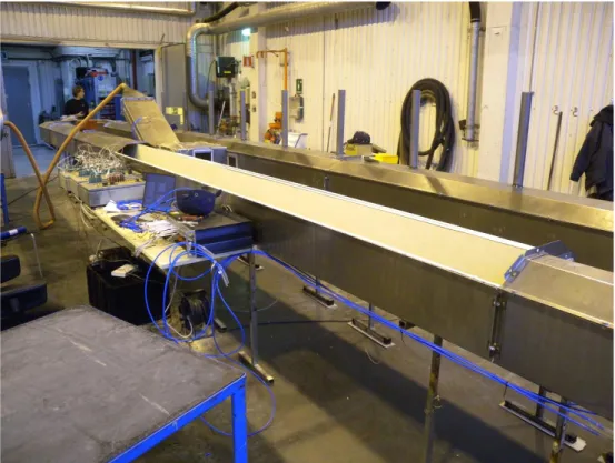
Figure 1. The experimental set-up. ... 12
Figure 2. Schematic diagram of the test set-up. ... 12
Figure 3. Photo of the test set-up. ... 13
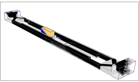
Figure 4. Schematic picture of the CFD model. ... 15
Figure 5. The area where the supply air flow is simulated in the upper part of the escalator shaft. ... 16
Figure 6. Ten exhaust air extraction points above the track area. ... 17
Figure 7. The exhaust air system with two platforms screen. ... 17
Figure 8. The conditions four minutes after the 20 MW fire reaches its maximum heat release rate. ... 19
Figure 9. The conditions about ten minutes after the 20 MW fire reaches its maximum heat release rate. ... 20
Figure 10.The positions of thermo-elements on the platform outside the door, at heights of 3,2 and 2,4 m above the platform surface. ... 21
Figure 11.The conditions four minutes after the 20 MW fire has reached its maximum heat release rate. ... 22
Figure 12.The conditions four minutes after the 20 MW fire has reached its maximum heat release rate. ... 23
Figure 13.The conditions four minutes after the 60 MW fire has reached its maximum heat release rate. ... 23
Figure 14.The conditions four minutes after the 20 MW fire has achieved its maximum heat release rate. ... 25
Figure 15.The main flow patterns of the exhaust air system. ... 25
Figure 16.The conditions four minutes after the 60 MW fire has reached its maximum heat release rate. ... 26
Figure 17.The conditions four minutes after the 20 MW fire has reached its maximum heat release rate. ... 27
Figure 18.The conditions four minutes after the 20 MW fire has reached its maximum heat release rate. ... 27
Figure 19.The conditions ten minutes after the 60 MW fire has reached its maximum heat release rate. ... 28
Figure 20.The conditions ten minutes after the 60 MW fire has reached its maximum heat release rate. ... 28
List of tables
Preface
We would like to thank the participants of the METRO-project and the funders of the project, namely the Stockholm Public Transport (SL), the Swedish Research Council Formas, the Swedish Civil Contingency Agency (MSB), the Swedish Fire Research Board (BRAND-FORSK), The Swedish Transport Administration (STA) and the Swedish Fortifications Agency (FMV) whom by their financial support made this project possible.
Special thanks to the technicians at SP in Borås and to Dr Anders Lönnermark for the advice during the performance of the tests and simulations.
Västerås in December 2012, Hans Nyman & Torkel Dittmer
Summary
This report summarises the work of Work Package 4 (WP 4), which is the part of the METRO project that focus on investigating the performance of various smoke control systems for use in underground stations having only one exit (the evacuation exit) to ground level. Two different smoke control systems, with two different configurations, were investigated, based on the results of a study of the literature:
A pressurizing (positive pressure) supply air system;
A pressurizing (positive pressure) supply air system, with platform screen doors; A mechanical exhaust air system, with extraction fittings above the track area; A mechanical exhaust air system, with platform screen doors.
Simulations were performed using FDS (Fire Dynamics Simulator, v 5.5.3), and investigating two different heat release rates, 20 MW and 60 MW. The calculations have investigated the conditions occurring at maximum heat release rates. All train doors on the fire-affected train, and doors from the escalator shaft bottom lobby to both the platforms have been assumed to be open. The criterion in the simulations was that the escalator bottom lobby must be kept clear of smoke.
The results show that both the pressurizing supply air system and the mechanical exhaust air system provide effective smoke control. Two fires were simulated: a 20 MW fire and a 60 MW fire. In the simulation three cases where studied, one without a platform screens, one with platform screens on the fire-affected side, and another one with platform screens on both sides with a dense construction on the non-affected side. A pressurizing supply air system requires an air flow of 20–40 m3/s for a 20 MW fire, and 40–80 m3/s for a 60 MW
fire depending on the openings in the platform screens. A mechanical exhaust air system requires considerably higher air flows: 75–100 m3/s to deal with the 20 MW fire, and
180 m3/s for the 60 MW fire. The temperatures on the platform with the burning train range
between 140 °C and 500 °C at a height of 2–3 m at the doors to the escalator bottom lobby. The advantages of a positive-pressure supply air system are a relatively simple installation and a lower requisite flow capacity of the fans. The disadvantage is that the smoke is not dispelled, but can spread to the other platform of the station and even to the next station. The advantages of a mechanical exhaust system are that the hot smoke is removed, and that the spread of smoke is restricted to the platform directly exposed to the fire.
Disadvantages include the need for a duct system (which requires space) and considerably higher fan capacities.
Metro – WP4
10 Hans Nyman & Torkel Dittmer
1
Introduction
Research into fire and underground facilities has increased enormously during the last ten years, with the main focus having been on fire and human behavior. In buildings or other types of construction work there should always be a possibility of two-way escape exits. A number of metros in Europe today have stations with only one exit. The purpose of the work presented here is therefore to analysis specific problems in metros with single-exit stations and to investigate smoke control systems in such stations. A fire in a single-exit station could be catastrophic, since the only way out could be blocked by the fire. One alternative to a second exit, which in existing cities could be very expensive and complicated, is a smoke control system combined with extinguishing system which secure the only exit. The purpose of the smoke control system is to remove smoke or to clear the exit from smoke to secure evacuation. The WP 4 has therefore focused on different systems for smoke control systems for single-exit stations. Input data has been provided by the results of the full-scale experiments performed in WP1, combined with results from performed model tests.
1.1
Method
The project was started with a study of the literature relating to smoke control systems in underground installations having only one emergency evacuation route. The results were presented to, and discussed with, scientists working on the project. Based on these discussions, two smoke control systems were selected for more in-depth analysis by CFD, using heat release rate input data based on results from WP 1.
The simulated model is that of an underground railway station with only one exit: it is closely based on Zinkensdamm’s station on the Stockholm underground. The input data for the simulations includes results from 1:20 model-scale trials carried out as part of the FORMAS project, which were performed at SP in Borås. About 30 simulations were run, but only eight are presented in this report. The reason for the large number of runs was to attempt to optimize the air flow rate in relation to the heat release rate and to the criteria that had been applied.
The report describes various arrangements of smoke ventilation systems, and determination of the necessary capacities to deal with two different fires.
1.2
Literature survey
The aim of the literature study was to find information on different smoke control systems in underground facilities for rail-borne traffic, at both national and international levels. First and foremost solutions relating to single-exit stations were examined. Only one article was found within this field. It described a safety system for a single-exit station including sprinklers, fire cell separations, pressurization of the escalator tunnel and smoke abstraction – specifically for the Zinkensdamm underground station.
The literature study shows that there have been two principles of smoke control systems in underground stations: thermal and mechanical smoke ventilation, with mechanical ventilation being the most common. The drawback of thermal smoke ventilation is that it is sensitive to air currents and that evacuation routes from the underground station can become smoke-filled. Mechanical smoke ventilation can be arranged in various ways: by positive-pressure pressurization, by exhaust air abstraction over the track area, or by use of the tunnels themselves as exhaust air routes. A further way of improving the situation in a fire in an underground facility is to utilize platform-edge screens, which provide additional separation with openings aligned with the train doors. The prime purpose of platform screen doors is to improve comfort and environmental conditions for passengers, in terms of reducing particulates and elevated temperatures, but they might also contribute to improved fire protection.
1.3
Model scale tests
Model scale experiments were carried out in SP’s facilities in Borås, using a model of an underground station with only one exit. The model was about 12 m long and about 1 m wide, on a scale of 1:20. It was based on the Zinkensdamm underground station in Stockholm, which provides a good example of an underground station with only one entrance/exit and two platforms linked to each other at one point via a platform-level stairwell/escalator lobby. The purpose with the model scale tests is to examine the effectiveness of various smoke control systems and to receive input data to the CFD modeling. The model consisted of two platforms and two track areas, in one of which latter the fire was simulated. An inclined tunnel, representing the escalator shaft, was connected to the platforms. The trials also included platform screen doors to separate platform and track areas. The two smoke ventilation methods that were used were pressurization via the escalator shaft, powered by a fan, and an exhaust air system above the tracks. In the pressurization trial, air was blown down the escalator shaft and into the platform-linking lobby at the bottom. From here, it was discharged via the two door openings on each side to the two platforms. In a few cases, one of the doors to the platform not exposed to the fire was shut: in the other cases, all four doors from the escalator bottom lobby were open.
The results showed that both smoke control systems works to prevent smoke from entering the lobby and escalator shaft. The criterion was the temperature increase in the lobby. The experiment showed that the thermocouples were affected by conduction through the model construction which was made of stainless steel. The higher fire effects were problematic because the exhaust ducts became very hot and were close deformation.
Metro – WP4
12 Hans Nyman & Torkel Dittmer
Figure 1. The experimental set-up.
The connections to the exhaust air system can be seen at the rear.
1.4
Experimental set-up
Figure 2 shows a schematic representation of the test set-up, with the escalator bottom lobby opening into the platform area through four open doors. The platform area consists of the passenger platforms and the tracks. The train with the fire was assumed to be standing at one of the platforms.
Figure 3. Photo of the test set-up.
The exhaust air extraction points were positioned in the roof above one track (see Figure 2– 3). The supply air fan in the first trials (pressurization) was connected to the upper part of the escalator shaft. There were a total of four doors in the escalator/stairwell bottom lobby, with two opening to each platform. The door sizes were 0,1 x 0,12 m. Air flows and temperatures were measured at various points in the model.
1.5
Results from the model scale tests
The results showed that both smoke control systems works to prevent smoke from entering the lobby and escalator shaft. The criterion was the temperature increase in the lobby. The experiment showed that the thermocouples were affected by conduction through the model construction which was made of stainless steel. The higher fire effects were problematic because the exhaust ducts became very hot and were close deformation.
During the experiments, it was found that the flow measurements were unclear; there were some uncertainty with respect to the flow measurement results (which was later confirmed with the CFD simulations). But an assessment of the results, converted to a full scale situation, shows that a pressurizing supply air system for a 20 MW requires a minimum of 20 m3/s and with a 60 MW fire about 30 m3/s. With mechanical exhaust air system (converted
to full scale) 50 m3/s is required at 20 MW fire and 100 m3/s with the 60 MW fire. These
values were used as very rough initial values for the CFD simulations. The later performed CFD simulations show that the flow measurements in the model tests were probably underestimated. But the model scale tests worked as a good foundation and a good
Metro – WP4
14 Hans Nyman & Torkel Dittmer
the conditions were under ventilated. These conditions cannot be replicated in the CFD model.
1.6
CFD – The FDS Fire Dynamic Simulator
CFD (Computational Fluid Dynamics) is a method in which computer programs are used to provide numerical solutions to a large number of equations defining positions or geometrical volumes over a specified period of time. Several commercial programs are available: FDS is one of the commonest for fire problems. It has been developed by the American National Institute of Standards and Technology (NIST) which, since 2000, has distributed the Fire Dynamics Simulator (FDS) CFD model as free software via its web site. Today, FDS, which is being continuously developed, has reached Version 6. It was created to be a means of solving practical fire engineering problems, but is also used for investigation of fundamental fire dynamics and combustion. In the simulations version 5.5.3 were used.
In FDS, the total calculation volume is divided into a large number of cells, or grids, for which the selected continuity equations are solved. These cells are generated as cubes or rectangular bodies which, in the normal case, are of the same size. In this case, a grid size of 0,20 x 0,20 x 0,20 m was used.
1.7
Acceptance criteria
In all fire protection technical projects, it is necessary at an early stage to decide what is to be achieved. In this particular case, the initial criterion has been that the escalator bottom lobby must be kept clear of smoke. Other criteria could be considered: e.g. to keep the escalator shaft clear of smoke, or limiting the temperature on the platform to some maximum value, or maintaining a certain minimum visibility. The choice of criteria will affect the design and capacity of the smoke control system.
1.8
Limitations
The calculations have investigated only two fully developed fires. Maximum heat release rate is achieved after one minute. The simulations have not considered air currents caused by external factors such as wind, train movements, or differences in temperature or height (chimney effects) in the tunnel system. The effects of such factors need to be considered from case to case. The simulations have not considered the whole tunnel system. The platform screens were placed 0,8 m from the train due to simulation reasons.
2
Model description
In the same way as in the model trials (Nyman, Dittmer, Lönnermark, & Gehandler, 2012), the model takes the Zinkensdamm underground station in Stockholm as its basis. The station has two platforms, 164 m long and 4,4 m wide. The two platforms are connected via the escalator bottom lobby, with two doors, 2,0 x2,4 m, to each platform, i.e. a total of four doors (see Figure 4). The inclined escalator shaft opens into the lobby with a cross-sectional area of 7,2 x 4,0 m. The vertical rise from the lobby level is about 10,0 m. The train consists of three cars, each 50 m long and 3,0 m wide. The track zone is 3,6 m wide, at a level of 1,4 m below platform level. All train doors on the train with the fire are assumed to be open: door size is 2,0 x 2,4 m. Both platform tunnel sections merge on each side of the station: the two platforms are thus joined via the shared tunnel section.
Figure 4. Schematic picture of the CFD model.
Metro – WP4
16 Hans Nyman & Torkel Dittmer
The train (blue) is behind the yellow platform-edge screen. The fire is in the carriage closest to the escalator bottom lobby (also blue). All the doors to the lobby are assumed to be open on both platforms, and all the train doors are also open. In the pressurization cases, air flow is assumed to be evenly distributed across the upper part of the section of the escalator shaft (see Figure 5).
Simulations with two different platform screen configurations were carried out. One with a platform screen on the fire side (as in Figure 6) corresponding to a worst case scenario. The other configuration included two screens with a totally sealed platform screen on the non-fire-affected side.
Figure 5. The area where the supply air flow is simulated in the upper part of the escalator shaft.
The supply air flows were varied between 20–100 m3/s in the cases with and without
platform screen doors. The exhaust air cases simulated ten 1 m2 extraction points above the
Figure 6. Ten exhaust air extraction points above the track area.
Each extraction point has an area of 1 m2.
The configuration with two platform screens is shown in Figure 7.
Figure 7. The exhaust air system with two platforms screen.
The air velocity in the simulations was varied, with the total air flows ranging from 30 m3/s
to 180 m3/s.
Metro – WP4
18 Hans Nyman & Torkel Dittmer
rate that was investigated. In the model, the fires were assumed to reach their maximum heat release rate after one minute, 20 MW and 60 MW respectively. With the model this corresponds to specific heat release rates of 833 kW/m2 and 2500 kW/m2 for the two fires.
2.2
Grid and simulation duration
The grid size used in the whole model was 0,20 x 0,20 x 0,20 m. For the purposes of the calculations, the model was divided up into a number of larger volumes (known as the mesh), in order to optimize the calculations (in some cases there were 14 volumes in one simulation). The simulation durations varied from 600 to 960 seconds.
2.3
Smoke control systems
Based on the results from the literature study, two different smoke control systems were investigated, in two different configurations:
A pressurizing supply air system. In this, the escalator shaft and bottom lobby are pressurized, with the two doors to each platform assumed to be open. Variations on this system exist today in various places around the world. The aim of the system is to keep the bottom lobby and the escalator shaft free of smoke. Earlier investigations have shown that the temperature on the fire side (the platform with the burning train) and the air velocity through the open doors are crucial for operation of the system. The pressurization can be delivered in practice by fans installed in the escalator shaft. A pressurizing supply air system with platform screen doors. This system is the same
as above, but with the addition of platform screen doors.
A mechanical exhaust air system, with extraction points above the track area. This system is based on the principle of removing as great quantities of smoke as possible and reducing temperatures as much as possible, so that conditions in the escalator bottom lobby and in the escalator shaft are not affected.
A mechanical exhaust air system with platform screen doors. The same as above, but with additional separation.
3
Results
The results of the simulations are described below. Only the boundary cases – i.e. the air quantities needed in order to keep the escalator bottom lobby free of smoke – are described.
3.1
Positive-pressure air supply system
The air is supplied via the escalator shaft. The model has assumed a uniform flow across the full cross-section of the shaft. Air is blown down the shaft and then on to the two platforms via the open doors in the shaft bottom lobby.
Figure 8. The conditions four minutes after the 20 MW fire reaches its maximum heat release rate.
The smoke control system is a pressurizing supply air system, with a capacity of 40 m3/s, and the platform does not have platform screen doors.
Metro – WP4
20 Hans Nyman & Torkel Dittmer
Figure 9. The conditions about ten minutes after the 20 MW fire reaches its maximum heat release rate.
The smoke control system is a pressurizing supply air system, with a capacity of 40 m3/s, and the platform does not have platform screen doors.
3.1.1 Pressurization without platform/track separation
In the 20 MW case, the calculations show that 40 m3/s of incoming air is needed in order to
keep the bottom lobby free of smoke. Figure 8 shows the conditions about four minutes after the fire has reached its maximum heat release rate. Figure 9 shows the conditions at the end of the simulation (11 minutes), corresponding to ten minutes simulation of maximum heat release rate. The incoming air also reaches its maximum delivery rate after one minute, and then remains constant.
The simulations show that the smoke spread relatively quickly, not only to the platform at which the burning train is standing, but also out into the running tunnel and on to the other platform. The pressurizing air supply system does not expel any smoke, but simply moves them to other part of the tunnel system. The four doors from the escalator bottom lobby each have an area of 4,8 m2, giving an estimated average speed of about 2 m/s through each
door. The highest temperatures, 3,2 m above the platform surface (see Figure 10) were measured as being about 200 °C. At a height of 2,4 m (the upper edge of the doors) the maximum temperature was measured at about 150 °C.
Figure 10. The positions of thermo-elements on the platform outside the door, at heights of 3,2 and 2,4 m above the platform surface.
If, instead, a 60 MW fire is assumed, then 80 m3/s of pressurized supply air are needed in
order to keep the escalator lobby free of smoke. In principle, the smoke flows are the same as in the 20 MW case; spreading along the platform suffering from the fire, partly out into the running tunnels and partly over to the adjacent platform. In this case, the average speed through the open lobby doors is about 3,1 m/s. The temperature 3,2 m above the platform surface outside the escalator lobby in this case is about 440 °C, while the temperature at the upper edge of the door (2,4 m above the platform door) is about 270 °C.
3.1.2 Pressurization with platform/track separation
For calculation-associated reasons, the platform screens are assumed to be positioned 0,8 m away from the train in the model. In a real situation they would probably be closer. All the doors in the screen are directly aligned opposite the open train doors, and are assumed to be open.
Two configurations are simulated. One with a platform screen only on the fire-affected side, and one configuration with platform screens on both sides. The one on the non-affected side is assumed to be dense.
With a 20 MW fire, this case also requires 40 m3/s of supply air in order to keep the
escalator bottom lobby free of smoke, i.e. the same flow rate with a platform screen on the fire-affected side as for the case of with no platform separation.
In principle, the smoke is spread in the same way as in the cases not having platform screen doors. The presence of screens somewhat delays the spread of the smoke (compare
Metro – WP4
22 Hans Nyman & Torkel Dittmer
In this case, the average air velocity through the open bottom lobby door is about 2,0 m/s, and the temperature about 3 m above the platform surface outside the lobby is about 210 °C. At the upper edge of the door (2,4 m above the platform surface), the temperature is about 110 °C.
In the case with two platform screens at both platforms the temperatures are in the same range as in the case with only one platform screen. But as expected the flow rate is reduced to 20 m3/s since the non-affected side is completely sealed which corresponds do a velocity of
approximately 2 m/s.
For the 60 MW fire, a supply air system in conjunction with platform screen doors (on one side) requires 80 m3/s to keep smoke out of the escalator lobby. This gives a theoretical
average air velocity through a door of 4,2 m/s. The respective temperatures were calculated as 280 °C (2,4 m height) and 490 °C (3,2 m height).
Figure 11. The conditions four minutes after the 20 MW fire has reached its maximum heat release rate.
The smoke control system is a pressurizing supply air system, with a capacity of 40 m3/s, and the platform and track are separated by platform screen doors.
Figure 12. The conditions four minutes after the 20 MW fire has reached its maximum heat release rate.
The smoke control system is a pressurizing supply air system, with a capacity of 20 m3/s, and both platforms and tracks are separated by platform screen doors.
Figure 13. The conditions four minutes after the 60 MW fire has reached its maximum heat release rate.
The smoke control system is a pressurizing supply air system, with a capacity of 40 m3/s, and both platforms and tracks are separated by platform screen doors.
In the simulations with platform screens at both platforms (60 MW), the required air flow rate is 40 m3/s (see Figure 13). The respective temperatures were slightly lower, compared to
the one-platform screen configuration, calculated as 230 °C (2,4 m height) and 380 °C (3,2 m height). Since the non-affected side is sealed the velocity over an open door is the same as in the case described in Figure 12, 4,2 m/s.
Metro – WP4
24 Hans Nyman & Torkel Dittmer
3.1.3 Discussion – supply air systems
The simulations show that a pressurizing supply air system is a good way of ensuring safe evacuation conditions, keeping the escalator shaft and its bottom lobby free of smoke by means of a relatively simple fan installation. The necessary air velocity through an open door in order to protect the space on one side against the spread of smoke depends on the temperature on the hot side. Previous investigations have suggested correlations for calculating air velocities through open doors, and the simulations confirmed these assumptions. The lower heat release rate gives lower temperatures on the platform, with the result that lower air flows through the open doors can keep the escalator bottom lobby free of smoke. The simulations show that up to about 4 m/s is needed in the case of the larger fire (60 MW), which produces a resulting temperature of about 490 °C at the door top level. The same air flow capacity is needed whether there are platform screen doors or not.
With platform screens on both sides and the assumption that the non-affected screen is dense the flow rate is reduced to 20 m3/s at 20 MW and 40 m3/s at 60 MW. The flow rate
corresponds to the reduced openings (the doors) towards the non-affected side.
Pressurizing air supply systems do not exhaust smoke and heat from tunnel systems, but drive it from one critical area to other, less critical, areas. A phenomenon that was shown by the simulations was the risk of the spread of smoke to the other platform: the amount of such spread depends on such factors as the design and geometry of the area where the two platforms meet. In certain cases, there are also pressure-relieving shafts that will affect the flow and spread of smoke.
Summarizing, pressurizing air supply systems are a good alternative to improve the evacuation situation. Their advantages include relatively simple installation, which can be accommodated in, for example, existing stations. A disadvantage is that they spread smoke to other parts of the tunnel system and destroy the smoke layer on the platforms. If platforms screens are used, in one-tube systems where the platforms are connected through the tunnel as in this case, smoke spread between the platforms will be prevented.
3.2
The mechanical exhaust air system
The exhaust air system consists of ten 1 m2 openings above the track area, as shown in Figure
6. The total air flow through the ten extraction openings in the model simulations was varied from 30 to 180 m3/s. The difference between the exhaust air system and the pressurizing
systems is that is that the former carry away heat and smoke from the tunnel system.
3.2.1 Exhaust air systems without platform screen doors
For the 20 MW fire case, an extraction rate of 100 m3/s is needed in order to achieve the
criterion of no smoke in the escalator bottom lobby. Figure 14 shows the conditions about four minutes after the fire has reached its maximum heat release rate. The spread of the smoke is limited to the one station tunnel, with the smoke not leaving the platform area. The platform temperatures close to the door are 150 °C at 3 m height, and 115 °C at 2,4 m height. The ten exhaust air openings are positioned above the train in the track area.
The simulations show that the incoming air is drawn from both tunnel tubes and in via the open doors of the escalator foot lobby (see Figure 15). The approximate flow distributions in
this case are that 35 m3/s are drawn in via the two tunnels (a total of 70 m3/s), and 15 m3/s
are drawn in from the escalator lobby. This gives a total flow of about 85 m3/s, while the
exhaust air flow rate is 100 m3/s. The difference is accounted for by the density difference of
the air at the higher exhaust temperatures.
Figure 14. The conditions four minutes after the 20 MW fire has achieved its maximum heat release rate.
The smoke control system is an exhaust air system, without platform screen doors, and with a capacity of 100 m3/s. Ten extraction openings, each of 1 m2 in
size, are positioned above the train.
Figure 15. The main flow patterns of the exhaust air system.
Supply air is drawn in from both running tunnels and from the escalator lobby, and is removed via the ten exhaust air openings in the roof.
Metro – WP4
26 Hans Nyman & Torkel Dittmer
Figure 16. The conditions four minutes after the 60 MW fire has reached its maximum heat release rate.
The smoke control system is a mechanical exhaust air system, with a capacity of 180 m3/s, and the platform and track are not separated by platform screen
doors.
In this case, the temperature about 3 m above the platform surface outside the lobby was about 320 °C. At the upper edge of the door (2,4 m above the platform surface), the temperature was about 150 °C. Most of the incoming supply air was drawn in from the two ends of the platform, in the same way as shown in Figure 3.8, with a smaller proportion coming from the escalator lobby. The actual quantities in this case were about 60 m3/s from
each end and about 5 m3/s from the escalator lobby.
3.3
Exhaust air system with platform / track separation
In the mechanical exhaust air scenarios with platform screen doors, the simulations show that the necessary air flow to control the smoke from the two fires is the same, whether or not there are platform screen doors on one side.
The 20 MW fire therefore requires 100 m3/s of exhaust air flow (see Figure 17 and Figure
18). The proportions of incoming supply air is about the same as in the case without platform screen doors: 35 m3/s from each end of the platform, and about 20 m3/s from the escalator
lobby. The temperature in this case was about 200 °C at a height of 3,2 m above the platform outside the lobby, and about 140 °C at the upper edge of the door (2,4 m above the platform surface), i.e. somewhat higher temperatures than in the case without platform screen doors.
Figure 17. The conditions four minutes after the 20 MW fire has reached its maximum heat release rate.
The smoke control system is a mechanical exhaust system, with a capacity of 100 m3/s, and the fire-affected platform and track are separated by platform
screen doors.
Figure 18. The conditions four minutes after the 20 MW fire has reached its maximum heat release rate.
The smoke control system is a mechanical exhaust system, with a capacity of 75 m3/s, and both sides are separated by platform screen doors.
Metro – WP4
28 Hans Nyman & Torkel Dittmer
Figure 19. The conditions ten minutes after the 60 MW fire has reached its maximum heat release rate.
The smoke control system is a mechanical exhaust air system, with a capacity of 180 m3/s, with platform screen doors on the fire-affected side.
Figure 20. The conditions ten minutes after the 60 MW fire has reached its maximum heat release rate.
The smoke control system is a mechanical exhaust air system, with a capacity of 180 m3/s, with platform screen doors on both platforms.
The 60 MW fire with platform screens on the fire-affected side requires an extraction air flow of 180 m3/s (the same as in the case without platform screen doors) in order to prevent
smoke from getting into the escalator lobby. The system also limits the spread of smoke. The temperatures are somewhat higher with the screens, being 380 °C and 170 °C respectively.
Figure 19 and Figure 20 shows the results of the 60 MW fire with platform screens on both sides. Also in this case 180 m3/s is required. The temperature in this case was about
450 °C at a height of 3,2 m above the platform outside the lobby, and about 200 °C at the upper edge of the door (2,4 m above the platform surface), i.e. somewhat higher
temperatures than in the case without platform screen doors and with one platform screen door.
3.3.1 Discussion – mechanical exhaust air system
The simulations show that the mechanical exhaust air ventilation system is a good smoke control system for use in underground installations. A capacity of 100 m3/s is required for a
20 MW fire, and 180 m3/s for a 60 MW fire without platform screen. With platform screens
on both sides the air capacity with the 20 MW fires is reduced to 80 m3/s. But with the
60 MW fire the same exhaust air flow rate is required with platform screens on both sides. In this case the presence or absence of platform screen doors does not affect the required flow capacity in order to prevent smoke from getting into the escalator lobby.
The big advantage of the mechanical exhaust ventilation system is that the smoke is extracted from the tunnel system. In addition, only one platform is affected by smoke, and not two, as is the case when using the pressurized supply air system. Incoming air is drawn mainly from the tunnel tubes at each end of the platform, with a smaller amount from the escalator lobby. Mechanical exhaust ventilation systems are better at controlling the spread of smoke, but require higher air flow rates, more equipment and more space.
3.3.2 Comparisons and observations
The supply air system is probably easier to install in existing stations since it does not require any duct system. The system needs lesser air quantities than a mechanical exhaust system to keep the lobby smoke-free. But the supply air system does not extract smoke from the running tunnels which means that long lengths of tunnel can suffer from smoke. The simulations were done with and without platform screen on the non-affected side, the truth is probably somewhere in the middle. All the doors in the train and the platform were open in the simulations (during the evacuation). If they are automatically closed after an evacuation, the situation and the fire development will change. In this one-tube configuration there is smoke spread between the platforms without the platform screens. The platform screen reduces the fan capacities with the supply air system. But the supply air system causes a lot of turbulence on the platforms.
With the exhaust system and the 20 MW fire and the platform screen reduces the air flow, but not in the 60 MW case. In case with the exhaust system, the smoke conditions on the platform gets worse with the platform screen on the fire affected side. (But our criteria was a smoke-free lobby, in this case) and the exhaust ducts are placed above the track area, not the platform area. In case of a failure, the big difference between the two smoke control systems is that the supply air system pollutes the fresh air.
Table 1 presents a comparison of the advantages and disadvantages of the two different smoke control systems.
Metro – WP4
30 Hans Nyman & Torkel Dittmer
Table 1. Advantages and disadvantages of the two different smoke control systems. System Advantages Disadvantages
Pressurizing
supply air system Relatively simple to install in existing stations etc. Requires no duct systems
Requires lesser air quantities than a mechanical exhaust system
Does not extract smoke from the running tunnels: long lengths of tunnel can suffer from smoke Smoke can reach the other platform Mixed smoke layer
Mechanical exhaust
ventilation system An effective system that extracts smoke from the tunnel system In comparison with the pressurizing system, lesser areas are affected by smoke
Large air quantities required A system of air ducts is required
4
Conclusions
This report has presented the results of a large number of simulations of the performance of two different smoke control systems for use in an underground railway station.
In all fire protection technical projects, it is necessary at an early stage to decide what is to be achieved. In this particular case, the initial criterion has been that the escalator bottom lobby must be kept clear of smoke. Other criteria could be considered: e.g. to keep the escalator shaft clear of smoke, or limiting the temperature on the platform to some maximum value, or maintaining a certain minimum visibility. The choice of criteria will affect the design and capacity of the fire gas control system.
The results show that both the pressurizing supply air system and the mechanical exhaust air system provide effective smoke control. Two fires were simulated: a 20 MW fire and a 60 MW fire. The required performance criterion was to keep the escalator bottom lobby free of smoke. To do so with a pressurizing supply air system requires an air flow of 20–40 m3/s
for a 20 MW fire, and 40–80 m3/s for a 60 MW fire depending on the openings in the
platform screens. In the simulation three cases where studied, one without platform screens, one with platform screens on the fire-affected side, and another one with platform screens on both sides with a dense construction on the non-affected side.
In a one-tube situation platform screen doors on both sides will prevent smoke from spreading from one platform to another.
A mechanical exhaust air system requires considerably higher air flows: 75–100 m3/s to
deal with the 20 MW fire, and 180 m3/s for the 60 MW fire. 75 m3/s is the required capacity
with platform screens on both sides. With 60 MW the presence or absence of platform screen doors does not affect the required flow capacity in order to prevent smoke from getting into the escalator lobby.
If some doors at the bottom of the escalators are assumed to be closed (e.g. by automatic door-closers), the necessary air flow to control the gases in the pressurizing air supply air flow scenario will be reduced. However, some of the most common automatic door closing devices can be sensitive to smoke detection, which means that they could open when they ought to be closed. The simulation calculations have also assumed that the doors in the platform screen doors on the fire-affected side are open.
The simulations have not considered air currents caused by trains, ambient wind conditions or temperature/height differences.
Metro – WP4
32 Hans Nyman & Torkel Dittmer
References
Fire Dynamics Simulator, v. 5.5.5. (2012). Retrieved from http://code.google.com/p/fds-smv/ Nyman, H., Dittmer, T., Lönnermark, A., & Gehandler, J. (2012). Model scale of a single exit
underground station. SP Report 2012:61, ISBN 978-91-87017-79-7. Borås: SP Technical Research Institute of Sweden.
METRO – WP4
This report summarises the work of WP4, a part of the METRO project. It investigates the performance of various smoke control systems for use in underground stations having only one exit to ground level. Two different smoke control systems with two different configurations were investigated: A pressurizing (positive pressure) supply air system; a pressurizing supply air system with platform screen doors; a mechanical exhaust air system with extraction fittings above the track area; and a mechanical exhaust air system with platform screen doors. Simulations were performed using Fire Dynamics Simulator, investigating two different heat release rates – 20 MW and 60 MW.
The results show that both the pressurizing supply air system and the mechanical exhaust air system provide effective smoke control. The advantages of a positive pressure supply air system are a relatively simple installation and a lower requisite flow capacity of the fans. The disadvantage is that the smoke is not dispelled, but can be spread to other platforms of the station and even to the next station. The advantages of a mecha-nical exhaust system are that the hot smoke is removed, and that the spread of smoke is restricted to the platform directly exposed to the fire. Disadvantages include the need for a duct system, which requires space, and considerably higher fan capacities.
The METRO project is a three year research project, financed by the Stock-holm Public Transport, the Swedish Fortifications Agency, the Swedish Civil Contingencies Agency, the Swedish Transport Administration, the Swedish Research Council Formas and the Swedish Fire Research Board.
The project is unique as nine Swedish organizations work multidiscipli-nary with the same aim – to make metro systems safer. The organizations are; Mälardalen University, SP the Technical Research Institute of Sweden, Lund University, FOI the Swedish Defense Research Agency, the Swedish For-tifications Agency, the Swedish National Defense College, Gävle University, the Stockholm Public Transport and the Greater Stockholm Fire Brigade. A study from MERO
This study is published within the MERO research area (Mälardalen Energy and Resource Optimization) at Mälardalen University. The research within MERO is directed towards various aspects of a sustainable society, with particular focus on the optimization and protection of community resources and infrastructure. The research groups within the area are mainly specialized in energy efficiency, resource conservation, design of sys-tems and processes, remediation of contaminated land and fire safety in underground facilities. A common denominator is all aspects of optimization and risk management, where modeling, simulation, validation and applied mathematics are important tools. Responsible research leader is Professor Erik Dahlquist.
http://www.mdh.se/forskning/inriktningar/mero
ISBN 978-91-7485-091-8
Box 883, SE-721 23 Västerås. Phone: +46(0)21-10 13 00 Box 325, SE-631 05 Eskilstuna. Phone: +46(0)16-15 36 00