Phase transformation and stability
studies of the Zr-H system
tuerdi maimaitiyili
Faculty oF engineering | lund university
Lund University Division of Materials Engineering Department of Mechanical Engineering ISBN 978-91-7623-552-2 ISRN LUTFD2/TFMT--15/1015--SE(1-65)
Phase transformation and stability
studies of the Zr-H system
Various hydride phases in the zirconium-hydrogen system have been prepared and studied both in situ and ex situ using high-energy synchrotron X-ray, neu-tron and conventional X-ray diffraction techniques. The crystal structure and stability of the present phases in the material as well as the phase transforma-tion order between phases were recorded, analyzed and presented.
Pr in te d b y M ed ia -T ry ck , L un d U niv er sit y 2 01 5 9 789176 235522 tu er d i ma ima it iy il i
Ph
ase t
ra
ns
fo
rm
ati
on a
nd s
ta
bil
ity s
tud
ies o
f t
he Z
r-H s
ys
tem 2
01
5
Phase transformation and stability
studies of the Zr-H system
Tuerdi Maimaitiyili
DOCTORAL DISSERTATION
by due permission of the Faculty of Engineering, Lund University, Sweden.
To be defended at lecture hall M:E (M-Building, LTH),
on 2015-12-03 at 10:15 AM
Faculty opponent
Organization:
Division of Materials Engineering Department of Mechanical Engineering LUND UNIVERSITY
P.O. Box 118
SE-221 00 Lund, Sweden
Document name:
DOCTORIAL DISSERTATION
Date of disputation: 2015-12-03
Author(s): Tuerdi Maimaitiyili Sponsoring organization: Swedish Research Council
Title and subtitle: Phase transformation and stability studies of the Zr-H system Abstract:
Zirconium alloys are widely used in the nuclear industry because of their high strength, good corrosion resistance and low neutron absorption cross-section. Zirconium has a strong affinity for hydrogen, however, and if hydrogen concentration builds up, the material will gradually degrade. In one class of such hydrogen caused degradation, called hydride induced embrittlement, hydrogen chemically reacts with zirconium forming one, or several, crystal phases of zirconium hydride. These hydrides play a primary, but sometime not fully understood, role in crack initiation and propagation within these materials. Despite the fact that hydride induced embrittlement in zirconium have been studied for several decades, there are still some unresolved issues.
It has been the aim of the research presented in this thesis to provide the research community with new and updated data of the hydrides themselves in order to aid further studies within the field of hydride induced embrittlement in general, and the mechanism of delayed hydride cracking in particular. To that end, the research presented here proceeded, in short, as follows: First, zirconium hydride powder, of well defined hydrogen concentration, was produced from commercial grade zirconium. This powder was subjected to heat treatment and the hydride phases were characterized both in situ and ex situ using neutron, synchrotron X-ray, and conventional laboratory X-ray based diffraction techniques. Next, most of the low-pressure zirconium hydride phases were produced under hydrogen/argon atmosphere from commercial grade zirconium powder. This process was simultaneously monitored and recorded in real time using synchrotron X-ray diffraction.
These experiments have produced new data of the behavior of different hydride phases during thermal treatment and in situ hydrogenation. For the first time all commonly reported zirconium hydride phases and the complete transformation between two different hydride phases were recorded with a single experimental arrangement. The phase transformation between δ and ε zirconium hydride was recorded in detail and presented. Finally, the controversial γ zirconium hydride was observed both in situ and ex situ and the preparation route, its crystal structure, and formation mechanisms were analyzed and presented.
Key words: Zirconium hydride, phase transformation, synchrotron X-ray diffraction, neutron diffraction, hydrogen induced degradation, in situ hydrogen charging, hydrogenation
Classification system and/or index terms (if any)
Supplementary bibliographical information Language: English ISSN and key title ISBN:
978-91-7623-552-2 (print) 978-91-7623-553-9 (pdf) Recipient’s notes Number of
pages: 161 Price Security classification
I, the undersigned, being the copyright owner of the abstract of the above-mentioned dissertation, hereby grant to all reference sourcespermission to publish and disseminate the abstract of the above-mentioned dissertation.
Phase transformation and stability
studies of the Zr-H system
Cover: Complete phase transformation in zirconium during hydrogenation and
dehydrogenation with different heating cycles (for details see Paper I).
Copyright Tuerdi Maimaitiyili
Division of Materials Engineering
Department of Mechanical Engineering
Lund University, Box 118, SE-221 00 Lund, Sweden
ISRN LUTFD2/TFMT--15/1015--SE(1-65)
ISBN 978-91-7623-552-2 (print)
ISBN 978-91-7623-553-9 (pdf)
Printed in Sweden by Media-Tryck, Lund University
Lund 2015
Materials Science and Applied Mathematics Dept. Media Technology and Product Development Faculty of Technology and Society, Malm¨o University
SE 20506 Malm¨o, Sweden Homepage: http://www.mah.se/
ix
Abstract
Zirconium alloys are widely used in the nuclear industry because of their high strength, good corrosion resistance and low neutron absorption cross-section. Zirconium has a strong affinity for hydrogen, however, and if hydrogen con-centration builds up, the material will gradually degrade. In one class of such hydrogen caused degradation, called hydride induced embrittlement, hydro-gen chemically reacts with zirconium forming one, or several, crystal phases of zirconium hydride. These hydrides play a primary, but sometime not fully understood, role in crack initiation and propagation within these materials. Despite the fact that hydride induced embrittlement in zirconium have been studied for several decades, there are still some unresolved issues.
It has been the aim of the research presented in this thesis to provide the research community with new and updated data of the hydrides themselves in order to aid further studies within the field of hydride induced embrittlement in general, and the mechanism of delayed hydride cracking in particular. To that end, the research presented here proceeded, in short, as follows: First, zir-conium hydride powder, of well defined hydrogen concentration, was produced from commercial grade zirconium. This powder was subjected to heat treat-ment and the hydride phases were characterized both in situ and ex situ using neutron, synchrotron X-ray, and conventional laboratory X-ray based diffrac-tion techniques. Next, most of the low-pressure zirconium hydride phases were produced under hydrogen/argon atmosphere from commercial grade zirconium powder. This process was simultaneously monitored and recorded in real time using synchrotron X-ray diffraction.
These experiments have produced new data of the behavior of different hy-dride phases during thermal treatment and in situ hydrogenation. For the first time all commonly reported zirconium hydride phases and the complete trans-formation between two different hydride phases were recorded with a single experimental arrangement. The phase transformation between δ and ε zirco-nium hydride was recorded in detail and presented. Finally, the controversial γ zirconium hydride was observed both in situ and ex situ, and the prepara-tion route, its crystal structure, and formaprepara-tion mechanisms were analyzed and presented.
xi
Acknowledgment
The work presented in this dissertation has been conducted at the Materials Science and Applied Mathematics group at Malm¨o University. This work would not have been possible without the support of many people around me. Here I would like to take this opportunity to acknowledge the support of many who helped me out along the past couple years. There have been far too many to name everyone individually so I will be brief:
I would like to thank my supervisor Dr. Christina Bjerk´en, for her valuable suggestions, encouragement and constant support during this research. I am also thankful for my supervisor Dr. Jakob Blomqvist for his patience and guid-ance. I am deeply grateful to Dr. Axel Steuwer for introducing this scientific field to our group and his generous help throughout the process. Dr. Olivier Zanellato spent a significant amount of his valuable time to teach me how to use the Topas Academic software package, and to share his insight into crystal-lography as well as data analysis with me. I am truly thankful for all his help. Dr. P¨ar Olsson, Dr. Matthew Blackmuir and Dr. Martin Fisk showed great interest in my work and we had many rewarding discussions which, provided me with a better perspective on my results. I would also like to acknowledge Dr. John Christopher Ion and Waleed Shoaib for proof reading my papers and thesis. Additionally, my special thanks go to all of the helpful and encouraging co-workers at the Faculty of Technology and Society at Malm¨o University who have helped directly or indirectly when I was in need of advice or support.
The Swedish Research Council (Grant no. VR 2008-3844) and Malm¨o Uni-versity are gratefully acknowledged for providing financial support for this project.
The European Synchrotron Radiation Facility (ESRF), Grenoble, France, the Forschungsneutronenquelle Heinz Maier-Leibnitz (FRM II), Garching, Ger-many, and the Australian Nuclear Science and Technology Organization (ANSTO), Australia are gratefully acknowledged for the provision of beam time. Professor Sven Lidin at the Division of Polymer & Materials Chem-istry at Lund University is gratefully acknowledged for providing access to his laboratory X-ray diffractometer and valuable discussion.
Last but not least, I am deeply indebted to my beautiful and caring wife Zhayida, lovely daughter Lale, curious son Malik and my loving parents for their support, encouragement and patience.
Malm¨o, Sweden Tuerdi Maimaitiyili
xiii
Appended papers
The thesis consists of an introduction followed by five appended papers. Paper I
In situ hydrogen loading on zirconium powder
T. Maimaitiyili, J. Blomqvist, A. Steuwer, C. Bjerk´en, O. Zanellato, M. S. Blackmur, J. Andrieux, and F. Ribeiro.
Journal of Synchrotron Radiation, 22(4):995–1000, Jul 2015. Paper II
The preparation of Zr-deuteride and phase stability studies of the Zr-D system. T. Maimaitiyili, A. Steuwer, J. Blomqvist, O. Zanellato, C. Bjerk´en, M. H¨olzel Submitted to Journal of Zeitschrift f¨ur Kristallographie - Crystalline Materials. Paper III
The phase transformation between the δ and ε Zr hydrides
T. Maimaitiyili, A. Steuwer, J. Blomqvist, M. S. Blackmur, O. Zanellato, C. Bjerk´en, J. Andrieux, and F. Ribeiro.
Under review, Journal of Nuclear Materials. Paper IV
In situ observation of γ-ZrH formation and dissolution by X-ray diffraction. T. Maimaitiyili, C. Bjerk´en, J. Blomqvist, J. Andrieux, O. Zanellato, Z. Wang, J.E. Daniels and A. Steuwer
Submitted to Journal of Alloys and Compounds. Paper V
Observation of temperature stability of γ-zirconium hydride by high-resolution neutron powder diffraction.
Z. Wang, A. Steuwer, N.Liu, T. Maimaitiyili, M. Avdeev, J. Blomqvist, C. Bjerk´en, C. Curfs, J.A. Kimpton, J. Daniels
Accepted for publication, Journal of Alloys and Compounds, 2015. Associated paper
In situ hydrogen charging of zirconium powder to study isothermal precipita-tion of hydrides and determinaprecipita-tion of Zr hydride crystal structure.
T. Maimaitiyili, A. Steuwer, J. Blomqvist, M. S. Blackmur, O. Zanellato, J. Andrieux, C. Bjerk´en, F. Ribeiro.
16th International Conference on Environmental Degradation of Materials in
Nuclear Power Systems-Water Reactors, August 11-15, 2013, North Carolina, USA. arXiv:1408.4665v1 [cond-mat.mtrl-sci].
xv
Contributions to co-authored papers
Paper I
Planning and conducting the major part of the experimental work. Fitting diffraction patterns and analyzing data.
Writing in close co-operation with the co-authors. Paper II
Planning and conducting the major part of the experimental work. Fitting diffraction patterns and analyzing data.
Writing in close co-operation with the co-authors. Paper III
Planning and conducting the major part of the experimental work. Fitting diffraction patterns and analyzing data.
Writing in close co-operation with the co-authors. Paper IV
Planning and conducting the major part of the experimental work. Fitting diffraction patterns and analyzing data.
Writing in close co-operation with the co-authors. Paper V
Sample preparations.
Checking and validation of the analysis.
Contents
Part I
1
1 Introduction 3
1.1 Background . . . 3
1.2 Objectives . . . 6
1.3 The structure of thesis . . . 7
2 The Zr-H system 9 2.1 Zirconium . . . 9 2.2 Applications of Zirconium . . . 11 2.3 Zirconium Hydrides . . . 13 2.4 γ-Zr Hydride . . . 14 2.5 δ- and ε-Zr Hydride . . . 15
2.6 Hydrogen induced degradation . . . 16
3 Materials and methods 19 3.1 In situ studies . . . 19 3.2 Diffraction techniques . . . 20 3.3 Powder diffraction . . . 23 3.4 Materials . . . 24 3.5 Experimental designs . . . 25 3.5.1 In situ hydrogenation . . . 25 3.5.2 Ex situ hydrogenation . . . 26
3.5.3 Neutron beam line setup . . . 26
3.5.4 Lab X-ray setup . . . 26
4 Structural analysis 29 4.1 Rietveld refinement . . . 29
4.2 Data refinements . . . 32
xviii CONTENTS 5 Summary of papers 35 5.1 Paper I . . . 35 5.2 Paper II . . . 36 5.3 Paper III . . . 36 5.4 Paper IV . . . 37 5.5 Paper V . . . 37
5.6 Future work possibilities . . . 38
Part II - Appended papers
51
Paper I 53
Paper II 61
Paper III 83
Paper IV 103
Chapter 1
Introduction
Zirconium (Zr) and its alloys are extensively used in the nuclear power in-dustry because of their combination of mechanical and chemical properties in high pressure/high temperature aqueous environment, structural stability un-der high doses of neutron radiation, and neutron transparency. However, Zr alloys have a significant affinity for hydrogen. Nonetheless, the accumulation of hydrogen slowly leads to degradation of its mechanical performance and may lead to e.g. delayed hydride cracking. Therefore, its behavior during manufac-turing, in service (reactor operation and storage) and under accident scenarios is of great importance and has been a topic of extensive research for decades.
This chapter will give an overall introduction to the project and thesis, and describe the main purpose of the research.
1.1
Background
Good compromise of mechanical, chemical and nuclear properties, such as ap-preciable strength, high melting point, good thermal conductivity and excellent corrosion resistance in almost all environments, makes Zr and its alloys a widely used group of engineering materials in many different areas ranging from daily consumer goods to aerospace components. By reason of superior nuclear stabil-ity and transparency to neutrons compared to other engineering materials, Zr based materials found their most important application in the nuclear power industry [1–4].
Zirconium alloys are mostly used as fuel rod cladding to hold the nuclear fuel pellets inside the reactor core of water cooled reactors, as illustrated in Fig. 1.1. During service, these fuel assemblies are in contact with the sur-rounding neutron moderator and coolant, which are commonly either light or heavy water (H2O or D2O) depending on the type of nuclear power plant.
Like the commonly used corrosion resistant engineering materials aluminum, magnesium and titanium, pure Zr readily reacts with oxygen and form a thin
4 CHAPTER 1. INTRODUCTION corrosion resistant oxide layer on the surface. As a result, that passive oxide coating prevents the bulk Zr metal from further oxidation, which then leads Zr to not react with water and air easily at normal conditions. However, as the environment inside the reactor core during operation is very harsh (250-350◦C, 7-15MPa, continuous irradiation by fast neutrons), the Zr alloy cladding eventually undergo aqueous corrosion according to the chemical reaction [5]:
Zr + 2H2O −→ ZrO2 + 2H2 (1.1)
Figure 1.1: An illustration of hydrogen induced degradation in nuclear fuel cladding.
Hydrogen is produced mainly by the corrosion reaction above and radiolysis of water, but can also be created through fuel oxidation, trapped hydrogen in the cladding materials and fuel pellets during production [5]. Among all those hydrogen sources, aqueous corrosion is the most dominant type [5]. As deuterium and hydrogen are chemically indistinguishable from each other, that chemical reaction described in Eq. (1.1) is also true for D2O, and in that case
deuterium gas (D2) will form instead of hydrogen gas (H2). From here on, only
hydrogen will be referred to although the knowledge is also valid for deuterium. Since at reactor operating conditions hydrogen is more stable in the Zr matrix than in gaseous form [6], a portion of hydrogen may be transported to the metal-oxide (Zr-ZrO2) interface and eventually absorbed into the cladding.
1.1. BACKGROUND 5 limited (almost zero) at room temperature [7], and brittle hydride phases will precipitate as soon as the hydrogen solubility limit is exceeded.
A phase is a region/domain in the system where intrinsic parameters have more or less the same value lattice structure, composition, density, etc. De-pending on whether there is a structural change or not, all phase changes can be categorized as either a phase transformation (with structural change) or a phase transition (without a structural change). For convenience however, here-after phase transformation is used for both cases. Phase transformation can take place when the system is not in equilibrium at any given thermodynamic variable. Paul Ehrenfest first introduced the concept and classification of a phase transformation order in 1933 [8]. According to this classification, the first-order transformation has a discontinuity in some order parameter with re-spect to some variable, such as temperature, and a second-order transformation has a discontinuity in the first derivative of this order parameter. Similarly, there are higher order transformations as well, but they are not common and will not be discussed in this thesis.
As the Zr hydride phases are brittle in nature and have a larger volume-per-unit than the Zr matrix, the formation of hydrides will introduce internal stresses and make the cladding tube more brittle and susceptible to cracking as illustrated in Fig. 1.1. Moreover, the hydrides in front of an existing crack may also provide an easy propagation path for further failure. It is believed that the precipitation of hydrides is the major cause of embrittlement of Zr alloys [9, 10]. Thus, the formation of hydrides is a potential issue during extended fuel burn-up [11], when reactors are taken off-line and cooled to an ambient temperature or during long-term handling and storage of used nuclear fuels. Therefore, to extend the life span of claddings, avoiding catastrophic failures and preventing possible radiation leakage during waste management, it is necessary to know the nature of various Zr hydride phases and their exact structures.
Despite the fact that Zr hydrides have been studied for several decades, still the basic nature and some mechanisms are not fully understood, owing to high diffusivity of hydrogen at low temperatures, structural similarities of various phases, extended hydrogen concentration intervals of hydride phases, and the influence of other impurity elements in the Zr-H system. The contro-versy pertains to the stability, crystal structure, formation mechanisms, and the transformation temperature of the phase denoted γ [2–4, 12–16]. Regard-ing the transformation between the two so called δ and ε phases, it is also not clear at what precise hydrogen concentration [17–19], at what temperature and in which transformation order [18, 20–24] they will transform.
Commonly, mechanical properties of the materials strongly depend on crys-tal structure, present phases and the way that the phases interact during the deformation/loading process. Different internal stress states are generated de-pending on crystal anisotropy, texture and orientational relationship between different phases. According to literature, the stability of various hydride phases depends on alloying elements and internal stresses that are considered [2–4].
6 CHAPTER 1. INTRODUCTION Hence, development of highly accurate theoretical models and understanding of the true nature of the the Zr-H system requires well defined experimental data. As many of these reported studies and structures are based on experi-ments carried out on ex situ hydrided polycrystal alloy samples using different techniques and facilities, there might be alloying/impurity elements effects or experimental discrepancies involved between different measurements. Thus, it is essential to perform high resolution in situ hydrogenation studies to answer some of the questions stated above. To the best of the author’s knowledge, up till now there has not been any such work performed on commercial grade Zr powder.
In order to decrease the knowledge gap and remove some of these discrepan-cies described here, a series of in situ and ex situ experiments have been carried out at various powerful synchrotrons and neutron radiation facilities. Sets of in situ hydrogen loading experiments have been performed at the high energy syn-chrotron radiation beam line ID15-B at the European Synsyn-chrotron Radiation Facility (ESRF) in Grenoble, France. An on-site high pressure/high temper-ature capillary system [25, 26] was used to hydrogenate commercial grade Zr powder to obtain all reported phases in the Zr-H system through one single setup and to follow their transformation. Rietveld [27–29] and Pawley [27–29] analyses were performed to determine the crystal structure of various phases.
In addition to in situ hydridation studies, externally hydrided commercial grade Zr powder also has been studied at the high-resolution thermal neutron structure powder diffractometer (SPODI) [30] at Forschungsneutronenquelle Heinz Maier-Leibnitz (FRM II), Garching, Germany; and Echidna at Aus-tralian Nuclear Science and Technology Organisation (ANSTO).
Experimental observation and findings presented in this dissertation enabled not only the direct observation of the hydride formation and phase transforma-tions, but also provided high quality data for crystal structure determination and in situ phase transformation studies. Furthermore, Zr is a d -electron metal, making it a prototype for understanding other important materials such as Ti and Hf, which also have a high affinity to hydrogen and form brittle hydrides.
1.2
Objectives
The work presented in this thesis is a part of a multi-disciplinary research approach, at Malm¨o University, constituted of several projects performed in collaboration with industry and other universities. The overall aim of these projects is to understand and describe the mechanisms of short- and long-term crack formation and propagation due to hydrogen induced embrittlement, and eventually develop a multi-level modeling strategy useful for industrial appli-cations. In addition to the present thesis, at Malm¨o University, the conditions for formation and evolution of metal hydrides are studied using atomistic cal-culations of hydride properties and thermodynamical quantities [1], as well as
1.3. THE STRUCTURE OF THESIS 7 meso-scale phase field modeling of dislocation and crack induced phase trans-formation [31]. The present work not only provides high quality experimental data to these modeling works, but it also has an important role during the process of validating theoretical models and proving hypotheses.
The main objectives of the work presented in this thesis is to investigate the hydride formation and transformation in commercial grade Zr powder to determine the effect of hydrogen content, hydrogen ordering, identification and determination of hydride phases, phase stability and transformation behavior. To study these relations, various types of in situ and ex situ studies have been carried out at state of the art, high resolution, non-destructive, 3rdgeneration synchrotron X-ray diffraction and neutron diffractions facilities. In addition, a series of conventional lab X-ray diffraction studies has also been performed. Considering the importance and controversial nature of the exact structure of γ-Zr hydride and its formation/transformation mechanisms, more focus is given to address the γ-Zr hydride related questions.
1.3
The structure of thesis
Considering that some parts of the research described in this thesis already are presented in the appended papers, parts of the thesis, including the introduc-tion, are kept short.
In Chapter 2, the Zr-H system is introduced and various Zr and hydride phases together with applications of Zr alloys are described in details. Chap-ter 3 gives a detailed description about maChap-terial selection and experimental techniques. Chapter 4 introduces the main data analysis tool called the Ri-etveld method, and describes data processing and fitting procedures. Chapter 5 presents a summary of the five appended papers. At the end, a short proposal of possible future extensions of the research is presented.
Chapter 2
The Zr-H system
Group IVB elements, such as titanium (Ti), Zr and hafnium (Hf), have very low terminal solid solubility (TSS) of hydrogen. Zr, for example, has a TSS of about 100 wt.ppm at 350◦C and almost zero at room temperature[32]. For that reason they all form brittle hydrides (MHx, M is Ti, Zr, Hf, and x is the H/M
ratio) as soon as the hydrogen concentration exceeds TSS. Since the degree of degradation is strongly dependent on the hydride structure, concentration, orientation and morphology, it is important to identify their exact structure and stability. Even today there is no clear agreement about the existing phases in the Zr-H system, position of the phase boundaries, stability of the hydride phases, phase transformation order and exact phase transformation tempera-ture [3, 4, 33].
This chapter first gives an overall introduction to Zr and its alloys. Then, it introduces main applications of Zr alloys in the nuclear industry. Next, the Zr-H system and various hydride phases are described, together with a short literature review regarding the γ-Zr hydride. At the end, hydrogen induced degradation in Zr alloys is also discussed.
2.1
Zirconium
The term zirconium originates from the Persian word zargon, which means gold like. It was first discovered in oxide form by the German chemist Mar-tin Heinrich Klaproth in 1789 while he was analyzing the mineral Jargon or zircon (ZrSiO4) from Sri Lanka. Three decades later, in 1824 the Swedish
chemist J¨ons Jacob Berzelius isolated low purity Zr powder, which was heavily contaminated with zirconia, through heating a mixture of dry potassium and potassium zirconium fluoride (K2ZrF6) in a small iron tube. Because of low
purity and oxide contamination, the Zr isolated by Berzelius looked black, and showed very low ductility [6, 34–37].
10 CHAPTER 2. THE ZR-H SYSTEM Zirconium is the 18th most abundant element in the earth crust with a
concentration of 150 ppm [34, 38]. Zr has five naturally occurring isotopes with one main oxidation state +4. Among five isotopes (90Zr,91Zr,92Zr,94Zr, 96Zr) of Zr, the 90Zr isotope is the most abundant with about 51.5% of the
total mass [38]. Zr can be found in over 100 different minerals in nature. However, it is mainly extracted from zircon (ZrSiO4) and baddeleyite (ZrO2),
or obtained as a by-product of titanium (Ti) productions through a process known as the Kroll Process [34, 36, 37]. In general, Zr production processes can be categorized into four main stages, such as mining, phase separation, reduction, sponge production and further processing depending on applications [38]. The full description of the whole production is out of the scope of this thesis.
The high purity Zr is soft and ductile, has low corrosion resistance, but at ambient temperature, Zr oxidizes quite easily and forms a thin protective oxide layer on the surface while changing from gray-white to dark [6, 35–37]. Because of that protective oxide layer, Zr develops excellent corrosion resistance to various acids and bases [36, 37]. As reason of its high oxidation nature, Zr with large surface to mass ratio (such as powder) is considered to be flammable and may ignite spontaneously at room temperature when exposed to oxygen/air [6, 35, 37].
As one of the Group IVB elements in the periodic table, Zr has similar properties as e.g. Ti and Hf. As shown in Fig. 2.1a, the phase diagram of Zr with respect to temperature and pressure is very similar to that of Ti. Owing to almost an identical ionic radii of Zr4+ and Hf4+ (72 and 71 pm respectively), these two show very similar chemical behavior [34, 39]. In fact, Zr and Hf exhibit complete solubility in each other as shown in Fig. 2.1b, and commercial Zr usually contains some amount of Hf impurities. As the neutron absorption cross-section of Hf is several hundred times higher than Zr, for better neutron economy (higher efficiency), Hf should be removed from reactor-grade Zr alloys [6, 36, 40, 41].
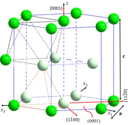
At ambient pressure and temperature below 863◦C, Zr has hexagonal close-packed (HCP) structure known as α-Zr, which is of Mg structure type with P 63/mmc space group symmetry (Fig. 2.2a). The unit cell constants of α-Zr
are a=3.2316 ˚A and c=5.1475 ˚A, and the c/a ratio is 1.593, which is slightly below the ideal valuep8/3=1.633 of perfect HCP but very close to the value of Ti (c/a=1.587) [3, 42, 45–49]. There are two atoms in each primitive unit cell, as shown in Fig. 2.2b, one at 000 and the other at 132312 or at 231312 [45]. There are two possible positions for interstitial atoms, and they are shown in Fig. 2.2b as red spheres. For more clarity, the magnified HCP unit cell with tetrahedron and octahedron positions is shown in Fig. 1 in the appendix. Because of the anisotropic crystal structure of α-Zr, its mechanical properties differ with respect to different crystallographic directions. For example, the elastic modulus of a single crystal Zr is 125 GPa in the c-axis direction and 99 GPa in the direction of [1010] [50]; the thermal expansion coefficients of Hf-free
2.2. APPLICATIONS OF ZIRCONIUM 11 0 5 10 15 Pressure [GPa] 0 500 1000 1500 2000 Temperature [ ° C] HCP (α) Hex.(ω) c a≈0.622(0.613) c a≈1.593(1.587) BCC (β) Liquid Ti Zr (a) 20 40 60 80 100 Hf [wt%] 1000 1500 2000 Temperature [ ° C] Liquid 1855◦C 2231◦C β-Zr, β-Hf (Im 3m ) α-Zr, α-Hf (P 63/mmc) 863◦C 1743◦C Hf Zr (b)
Figure 2.1: (a) Compiled temperature–pressure phase diagram of Zr and Ti based on experimental data provided in [42]; and (b) binary Zr-Hf phase dia-gram [43, 44].
Zr in the a and c directions are about 5.15×10⁻⁶ K−1 and 11.03×10⁻⁶ K−1, respectively, in the temperature interval 27 to 827 [51].
At higher temperatures, α-Zr allotropically transforms into body-centred cubic (BCC) phase while the pressure is still low. This cubic phase is known as β Zr phase, which is of W structure type with Im3m space group symmetry and a lattice constant a=3.6090 ˚A[3, 42, 45, 47]. The crystallographic building blocks of this phase is shown in Fig. 2.2c. Under increased pressure while at room/low temperatures the HCP phase transforms into another hexagonal structure called ω phase, which is not close packed as it is a low temperature and low pressure allotrope [3, 42, 45, 47]. At higher temperatures, the ω phase transforms into the BCC phase. In contrast to α-Zr, the ω phase has three atoms (000, 231312, 132312) [45] in a unit cell with the lattice constant a=5.0336 ˚
A and c=3.109 ˚A, respectively. The ω phase have P 6/mmm space group symmetry (AlB2 structure prototype) [3, 42, 45, 47, 48]. From a materials
engineering perspective, the appearance of the ω phase at high pressure is interesting because the ω phase appears to be fairly brittle compared to the α phase [42, 47, 48].
2.2
Applications of Zirconium
Like any other structural materials, such as pure iron (Fe), pure Zr is soft and does not have appreciable strength for construction. However, through alloying the mechanical strength of Zr will significantly improve with tensile
12 CHAPTER 2. THE ZR-H SYSTEM
(a) (b) (c)
Figure 2.2: (a) HCP structure; (b) the primitive HCP unit cell, with two possible interstitial atom positions (in red); and (c) BCC structure.
strength ranging from 200 to 1100 MPa in the temperature interval 20 to 482 [52]. Compared with other conventional structural materials, Zr and its alloys not only have good mechanical properties and corrosion resistance under high pressure and high temperature condition, but importantly they also have appreciable neutron transparency together with low creep at high temperatures, and low coefficient of thermal expansion [1–4, 53]. The relative neutron capture cross-section and other physical properties of some common structural materials are presented in Table 1 and Fig. 2 in the appendix. Thus, Zr alloys mostly are used in the nuclear industry for fuel cladding, fuel channels, control rod guide tubes, grid spacers and fuel containers [3, 53–55]. Over the years, to improve the performance of Zr alloys many types were developed. To improve corrosion and hydride formation resistance without losing neutron transference, Zr is mainly alloyed with niobium (Nb) and tin (Sn), and together with other minor elements. A few of the most commonly used and recently developed Zr alloys are listed in Table 2 in the appendix.
In addition to nuclear applications, Zr and its alloys have many different usages. Thanks to the excellent corrosion resistance of Zr towards many dif-ferent acids, bases and seawater, Zr and its alloys are extensively used in the chemical industry, electric power and offshore business [34, 35, 38]. Because of the high melting and boiling points of Zr, it used in high temperature envi-ronments as a refractory material [34, 35]. The compound zircon is used as a semiprecious gemstone [34, 35]. Since Zr does not have any known biological hazards, it is also used for surgical instruments as well as implants[34, 35, 38]. Additionally, Zr-based alloys also have an important use in aircraft and space devices [6, 53, 56].
2.3. ZIRCONIUM HYDRIDES 13
2.3
Zirconium Hydrides
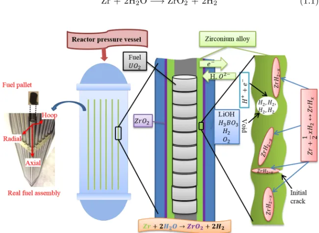
Since the formation of different hydride phases is dependent on hydrogen con-centration and cooling rate [3, 4, 55], the Zr-H system is quite complex and hard to study. After the identification of Zr hydride related problems in the 1950s [9], numerous studies have been carried out on the Zr-H system, and almost every five to ten years there are some corrections made on the proposed binary Zr-H phase diagram [3, 33]. According to most of the published litera-ture [1–4, 17–24, 33, 57–59], there exists at least three different hydride phases at ambient temperature under atmospheric pressure (Fig. 2.3) depending on hydrogen concentration and quenching rate.
0 0.5 1 1.5 2 wt% H 0 200 400 600 800 1000 Temperature [ ° C] 286 ° C 180 ° C 0.7 1.4 0.07 550 ° C ǫ β-Zr δ α-Zr γ α+δ+ ζ
Figure 2.3: Binary Zr-H phase diagram based on data provided in [3] (Reported metastable phases are enclosed in dashed rectangles).
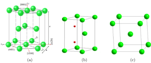
Phases reported in the Zr-H system include two allotropic forms of Zr as mentioned earlier; two stable hydride phases, the face centered cubic (FCC) Zr hydride known as the δ Zr hydride phase, which is of CaF2 structure
type (Fm3m, ZrHx=1.4−1.7, a=4.7783 ˚A) and the face centered tetragonal
(FCT) ε Zr hydride with ThH2 structure (I 4/mmm, ZrHx=1.75−2, a=4.9689
˚
A, c=4.4479 ˚A, c/a < 1); two metastable hydride phases, the FCT γ hydride phase with structure type ZrH (P 42/n, ZrHx=1.0, a=4.592 ˚A, c=4.970 ˚A, c/a >
1), and one newly observed trigonal ζ hydride (P 3m1, a=3.242 ˚A, c=10.33292 ˚
A, ζ-ZrHxwhere 0.25≤ x ≤0.5) [1–4, 33, 57, 60]. The crystal structure of the
three most commonly reported hydride phases are illustrated in Fig. 2.4, and basic crystallographic data are tabulated in Table 3 in the appendix. Accord-ing to Zhao et al. [57], the ζ-ZrHx is fully coherent with the α-Zr matrix and
14 CHAPTER 2. THE ZR-H SYSTEM speculated to be a precursor of the δ and γ-ZrHx formation. However, this
new phase has not been conclusively confirmed experimentally by others, and neither was it observed in the work presented in this thesis. Therefore, it will not be discussed in detail here.
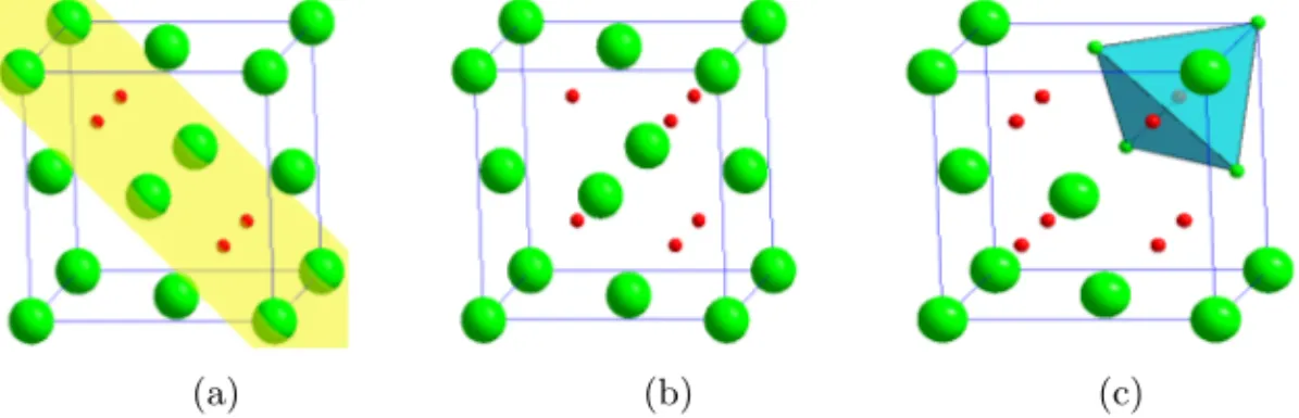
(a) (b) (c)
Figure 2.4: Crystal structure of (a) γ-, (b) δ- and (c) ε Zr hydrides. The green spheres represent Zr atoms and red spheres H atoms.
The type of hydrides formed in Zr-based alloys and their morphology are de-termined by many factors, including purity of the Zr, hydrogen concentration, heat treatment, external load, strain rate and cooling rate [3, 4, 55, 57, 61]. In principle, interstitial atoms such as hydrogen can occupy either octahe-dral or tetraheoctahe-dral interstitial sites in α-Zr, but because of the lower absorp-tion/dissolution enthalpy of tetrahedral sites in HCP α-Zr, hydrogen tends to solely occupy these [49]. All eight possible tetrahedral sites in the unit cell of the ε-Zr hydride are completely filled with hydrogen atoms, while they are partly filled in the δ-Zr hydride [1]. Nevertheless, it is not clear that in the case of δ-Zr hydride whether the occupancy is random, or if a long- or short-range order is present. In general, Zr hydride tends to form as needle- or plate-like precipitates, which can be approximated by long ellipsoids [62].
2.4
γ-Zr Hydride
Although many studies have been carried out on γ-ZrH, there is still contro-versy regarding its stability, crystal structure, formation mechanisms, and the transformation temperature [2–4, 12–15, 63–66].
Most of the past [4] and recent [60, 66] literature reports that the γ-ZrH is a metastable phase, which is of FCT structure with space group P42/n and forms
upon fast cooling/quenching (Fig. 2.4a). In this crystallographic structure, the Zr atoms are located at the 141414 sites while the hydrogen atoms occupy the 000 or 0012 sites [2–4, 49] and four hydrogen atoms occupy tetrahedral sites on al-ternate (110) planes with a concentration of x ≈1. . However, Kolesnikov et al. [15] reported that the structure of γ-Zr hydride is face-centered orthorhombic (b/a ≈1.015, c/a ≈1.091) with space group Cccm and the hydrogen unit-cell
2.5. δ- AND ε-ZR HYDRIDE 15 fractional coordinates 143414, 341414, 143434, 341434. The transformation from a sin-gle crystalline hexagonal Zr to tetragonal γ hydride produces three possible orientation variants. More information regarding transformation between ori-entations and mean-field strain calculation after hydride formation based on an inclusion model can be found in [62].
By reason of the lower surface energy of γ hydride, it may nucleate in preference to δ hydride [23, 67], and higher hydrogen concentration may lead to formation of more δ hydrides while the opposite lead to more γ hydrides [63, 68]. A few reports suggest that γ phase is the stable room temperature phase, with a δ to γ transformation at 180 [14, 64, 65] or at 255 [69], while others quote the δ phase as being the stable room temperature phase with no such transformation [3, 4, 13, 70]. Regarding the presence of δ to γ phase transformation reported in [14, 64, 65], it was hypothesized that such transfor-mation may be caused by dislocation loops and memory effects. Most reports agree that the formation of γ hydride favors higher cooling rates (>10/min), while δ hydride is often found after slow cooling [3, 4].
Even though the density functional theory calculations on the energetics of the γ hydride in the Zr–H system suggests that it is the equilibrium hydride phase below 200◦C [71], no γ hydride was detected experimentally in that temperature range [67].
Based on a literature review and a series of experimental investigations, in 2004, Lanzani et al. [4] concluded that the stability of γ-ZrH could be related to the purity of the Zr alloy. According to them, the γ-ZrH is a dominant stable phase in high purity Zr (>99.9 wt.% Zr) and its amount may increase at room temperature or after aging at about 200◦C, whereas in less pure zir-conium (<99.8 wt.%) the γ-ZrH could be a metastable phase, and its amount increases with the increasing cooling rate. In addition, based on many diverse observations, Lanzani et al. [4] speculated that in high purity Zr there might be a peritectoid reaction (α-Zr + δ-ZrHx −→ γ-ZrH) at about 250◦C, while
with lower purity (<99.8 wt.% Zr) there is no such transformation.
2.5
δ- and ε-Zr Hydride
Both δ- and ε-Zr hydrides are widely accepted as stable room temperature phases [3, 4], and it is relatively easy/common to synthesize them in the labo-ratory. Nevertheless, reported hydrogen concentration intervals of ε-Zr hydride (1.75<x <2) and its transformation behavior from δ are still questionable [17– 24, 72]. Even today it still not clearly defined that at what precise hydrogen concentration [17–19], at what temperature, and in which kind of transforma-tion order [18, 20–24] the FCT ε-ZrHx transforms into FCC δ-ZrHx, and vice
versa.
Based on ab-initio calculation, Ivashchenko et al. [21] concluded that the cubic-to-tetragonal phase transformation in ZrH2is of “first-order which is close
16 CHAPTER 2. THE ZR-H SYSTEM al., Cantrell et al. [22] also proposed a pseudo-martensitic transition that is of first-order with a very narrow two-phase region based on their nuclear magnetic resonance (NMR) and X-ray diffraction studies of this transition. However, other experimental evidence showed that the δ-Zr hydride martensit-ically transforms to ε-Zr hydride [18, 23]. Moore et al. [72] on the other hand concluded that there is a first-order transition at the boundaries of the δ + ε two phase region, and second-order transition at the boundary of the δ and ε single phase regions with their high-temperature X-ray diffraction studies, which was supplemented with dilatometric and electrical resistance measure-ments (Fig. 2.3). According to Zuzek et al. [3], such discrepancies regarding the exact phase transformation order between δ and ε might have been caused by the experimental difficulties in obtaining true equilibrium, and also by the effects of oxygen impurities in the system. Therefore, to define exact transfor-mation order, temperatures and hydrogen concentrations of these two phases, it is critical to perform high resolution in situ experiments on well defined samples.
2.6
Hydrogen induced degradation
Once hydrogen enters Zr and its alloys, it will manifest itself in the form of hydride blisters, hydrogen micro-bubbles, loss of plasticity, weakening of grain boundaries and delayed cracking [9, 10, 73]. Worsening of any of these hydrogen related problems requires continuous transportation of hydrogen inside the Zr-matrix through Zr-oxide layers. The exact mechanism of hydrogen absorption and transportation is still not clear [74], but it is commonly believed that the hydrogen in Zr can be transported directly in the thin oxide layer by using de-fects as pathways, or using the second phase particles (SPP) as transportation short cuts when the oxide layer is relatively thick [38, 75].
Owing to different crystallographic structure, atomic packing and thermal expansion of Zr phases, it is quite natural to expect each Zr phase to have different formation and transformation temperatures which are dependent on hydrogen solubility. As shown in the Zr-H binary equilibrium phase diagram in Fig. 2.3, the solubility of hydrogen in α-Zr is very limited (60.069 wt.% at 550). In contrast, the solubility of hydrogen in β phase is much higher than in the α phase, and more than 1.2 wt.% hydrogen can be dissolved in Zr above 800. Therefore, as hydrogen-saturated Zr cools from the β phase region to the α phase region will result in excess hydrogen and contributes to nucleation and growth of hydrides. The boundary that defines the maximum hydrogen solubility at a certain temperature is called the terminal solid solubility (TSS). As a result of misfit strains between hydride and matrix [76] together with the under-cooling that is needed for initiating hydride nucleation, there will be a hysteresis in the TSS for precipitation and dissolution [7, 70].
All hydrides formed in Zr (also in Ti) make the material brittle and de-grade their mechanical properties disregarding the hydride structure and type.
2.6. HYDROGEN INDUCED DEGRADATION 17 According to some studies [70, 77], the volume expansions caused by phase transformations of α-Zr → γ-ZrH and α-Zr → δ-ZrHxcan reach as high as 12.3
% and 17.2 % per unit cell, respectively. Hence, the precipitation of brittle hydrides will introduce a significant amount of misfit strain in the Zr matrix, which reduces its ductility. In most of the hydride forming metals, the em-brittlement takes two forms, such as short-term loss of toughness that is time independent and long-term time-dependent crack growth mechanisms. In the later case, hydrides nucleate and grow slowly at stress raisers, such as a crack tip, micro cracks or defects in the materials, until they reach the critical size required for crack initiation, then eventually results in crack growth, and the process repeats itself at the new crack tip until complete failure. Since in this process the hydride formation and crack growth requires certain time in each cycle, it is called delayed hydride cracking (DHC). It has been identified that the DHC mechanism is responsible for radial cracking starting at the outside surface of boiling water fuel claddings when power is ramped up after a high burn-up [78–80].
The degree of degradation after hydride formation depends not only on the quantity of hydride phases in the system, but also on hydride morpholo-gies, such as orientation, density and distribution, in respect to the applied stress [79, 80]. Most hydrides found in commercial Zr alloys are predominantly δ hydride at lower hydrogen concentration and ε hydride at higher hydrogen concentration. It is observed that both δ and ε hydrides orient themselves cir-cumferentially in Zr alloy cladding tubes while in the reactor core. However, research evidence showed that under applied tensile stresses these hydrides re-orient radially to become perpendicular to the applied stress, which increases the possibility of major cladding failure [2, 36, 81, 82]. Therefore, understand-ing exact hydride structure as well as their stability have a major role on guaranteeing the integrity of the fuel cladding.
Chapter 3
Materials and methods
There are many factors that can strongly influence conclusions/observations made about the Zr-H system. All problem raisers, other than human errors, can be split into two major groups, as material dependent or experimental technique related. Having well defined samples, setups and data collection techniques together with solid analysis methods are keys to avoiding many possible discrepancies.
This chapter will describe various experimental techniques which are used in this work together with their theoretical basis.
3.1
In situ studies
In the past, Zr hydride and hydrogen behavior in Zr alloys was investigated by ex situ studies with techniques such as TEM, SEM, conventional lab X-ray diffraction and metallographic observation [3, 24, 46, 72, 79]. With these tech-niques, it is possible to perform morphological and structural investigations. However, from literature [1–4], it is evident that in the Zr-H system there are metastable and low temperature hydride phases that only exist at specific tem-peratures and conditions. This means that the above mentioned techniques are of limited use due to risk of issues, such as data discontinuity before, during and after the experiment, depending on the system environment. In situ studies, on the other hand, enable real-time observations while the system is under varying conditions, such as temperature, pressure, concentration and load variations. Thus, to understand the true behavior of hydrogen in Zr and the characteristics of various Zr hydride phases, it is essential to conduct highly accurate in situ studies. Neutron and synchrotron X-ray diffraction are two of the most widely used in situ techniques for this purpose.
20 CHAPTER 3. MATERIALS AND METHODS
3.2
Diffraction techniques
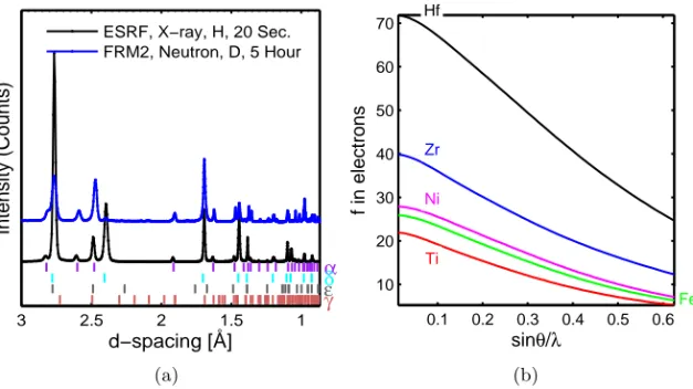
A diffraction pattern is a fingerprint of a material, see e.g. Fig. 3.1a, which can give us detailed information about its content and possible thermal/mechanical history. In that and all other diffractograms presented in the thesis, all the color coded small vertical bars under the diffraction pattern corresponds to estimated HKL peak positions of phases labeled with the same color. Some of the corre-lations between mechanical properties of materials and the constituent atoms, crystallographic structure, atomic position, chemical interaction and defects can be extracted just by inspecting the peak position, peak intensity/hight and peak broadening on observed diffraction patterns [83–85].
Because of the wave and particle duality of X-rays and neutrons together with their short wavelengths, which are comparable with atomic lattice spac-ing, both neutron and X-ray diffraction techniques enable us to measure the absolute atomic spacing in crystals and collecting high quality diffraction data. The fundamental principals of neutron and X-ray diffractions are the same. Both are based on the particular use of Bragg’s law:
λ = 2dsinθ, (3.1)
where λ is the wavelength of the radiation, θ is the diffraction angle, and d is the inter-atomic spacing.
To have a diffraction pattern, the material must be crystalline and the spac-ing between atomic layers should be close/comparable to the probspac-ing radiation wavelength. If beams diffracted by two different atomic layers are in phase, constructive interference occurs, and the diffraction pattern shows characteris-tic diffraction peaks. If atomic layers are out of phase, destructive interference occurs and there will be no peaks. In addition, to have a good resolution in reasonable time, the probing beam should have enough flux, which is detectable after the interaction with matter. As X-rays are charged particles, they inter-act with the electron cloud surrounding the atom nuclei in the target, hence, the penetration power of the X-ray is relatively small compared to that of the neutral neutrons. Furthermore, the scattering power of the X-rays depends on the number of electrons in the particular atom and the scattering angles. The X-ray scattering power of an atom decreases with increasing scattering angle and is larger for heavier atoms. The electron number and angular dependence of the X-ray diffraction can be seen clearly from a plot of scattering factor f in units of electrons versus sinθ/λ for a few selected materials, including Zr and Ti, see Fig. 3.1b. It should be noted that for a zero scattering angle, the value of f equals the number of electrons. On the other hand, for neutrons of the same wavelength the scattering factor is not angle dependent and is considered to be the same for all angles. This is mainly due to the fact that the atomic nucleus is much smaller than the electron cloud [86]. In addition, every atom and its isotopes have their own unique neutron scattering strengths, which is independent of atomic number. For that reason, neutron diffraction is very
3.2. DIFFRACTION TECHNIQUES 21 good for studying the effect of light elements in the presence of heavy ones either directly or by isotopic substitution. For example, the neutron scattering strength of D is order of magnitude larger than that of H, so by substituting H with D it is possible to determine the exact position of D atoms in a hy-dride crystal structure and monitor their thermal motions far more precisely with neutrons than with X-rays. Furthermore, neutrons have spin and strongly interact with magnetic moments, so neutrons are very good for studying mag-netic properties of the materials [85, 86]. Lastly, in contrast to neutrons the instrumentation of X-rays in general are easier (e.g. focusing and guiding), and there is less concern about radiation safety.
1 1.5 2 2.5 3 d−spacing [Å] Intensity (Counts) α δ ε γ ESRF, X−ray, H, 20 Sec. FRM2, Neutron, D, 5 Hour (a) 0.1 0.2 0.3 0.4 0.5 0.6 10 20 30 40 50 60 70 Zr Ti Hf Fe Ni sinθ/λ f in electrons (b)
Figure 3.1: (a) Comparison of diffractograms collected at neutron and syn-chrotron X-ray sources. (b) X-ray scattering factor f of a few selected elements. Figure 3.1a shows the comparison of data collected from Zr powder, that was hydrogenated by two different hydrogen isotopes. The diffraction pattern in black is collected with synchrotron X-rays at ESRF from hydrogenated Zr powder for 20 seconds. The pattern in blue is from deuterated Zr powder obtained with neutrons at FRM II for five hours. As shown in Fig. 3.1, the intensity of the characteristic peaks from X-rays decreased significantly from a lower angle to a higher because of the angular dependence of X-ray scattering. However, the neutron data did not show such angle dependence. In addition, because of much higher flux of the X-rays, the diffraction pattern from ESRF was acquired 900 times faster than the neutron showing comparable diffraction intensity for both hydride and matrix.
X-ray intensity and flux generated by a synchrotron facility are of many orders of magnitude larger than the best conventional lab X-ray and neutron sources can produce, therefore it can also penetrate deep into a material
sim-22 CHAPTER 3. MATERIALS AND METHODS ilar to neutrons and allows one to obtain intense high resolution data in a short time, which is essential for fast in situ phase transformation studies in transmission mode as demonstrated in Fig. 3.1a. This can be further illus-trated by Fig. 3.2a, which shows that, with high energy synchrotron X-rays, it is quite possible to study several millimeters thick metal/alloy samples non-destructively. Moreover, synchrotron X-rays are highly collimated (residual divergence less than 20 micro-radian), photon wavelength resolution is high (4λ/λ better than 2×10⁻⁴), wavelengths are easily tunable, and temporal and spacial resolutions are good. Therefore, synchrotron X-rays are very suitable for studying complicated problems and performing in situ studies. However, synchrotron radiation sources are not always easily accessible and requires cer-tain waiting periods. In contrast, the conventional lab X-ray sources are often easier to get access to, and they can be suitable for routine and structural analyses of problems of medium difficulty.
(a) 1 1.5 2 2.5 3 d−spacing [Å] Intensity (Counts) α δ ε γ FRM2 RT, Neutron, D ANSTO RT, Neutron, D (b)
Figure 3.2: (a) X-ray penetration depth and photon energy relation of few selected engineering materials [87]. (b) Comparison of the same deuterated Zr powder diffractograms collected at two different neutron diffractometers.
In summary, neutron, conventional lab X-ray and synchrotron X-ray diffrac-tion techniques all have their advantages and disadvantages. None of these methods universally work for all kinds of problems. Different instruments at different facilities based on same techniques may also give slightly different re-sults, as presented in Fig. 3.2b. Thus, these techniques as well as different facilities are complimentary to each other, and it is always important to do comparative studies when investigating material structures and their proper-ties.
3.3. POWDER DIFFRACTION 23
3.3
Powder diffraction
Most often, all real materials have various kinds of defects that most likely destroy the periodic atomic arrangement in three dimensional space and lead to destructive interference. Therefore, to ensure a good diffraction signal, the single crystals are sometimes used in various investigations. However, for cer-tain materials such as compounds, it is very difficult to produce a single crystal large enough for high resolution measurements.
As illustrated in Fig. 3.3, the powder of a specimen consist of randomly oriented perfect small/single crystallites originating from imperfect crystals. In powder diffraction, all crystallite orientations are in principle equally probable, and there will be a number of small crystallites at the correct orientation (θ1)
for any given inter-atomic spacing (d1) that satisfies Eq. (3.1) for a given
wavelength (λ):
sinθ1=
λ 2d1
(3.2) Since each crystallite is randomly oriented, similar planes in different crys-tallite scatter in different directions. Thus, a cone of diffracted rays, with a semi-vertex angle of 2θ1 is produced, as shown in blue in Fig. 3.3. Similarly,
there are numerous other crystallites at the correct orientation, θ2, to satisfy
Bragg’s law for planes spaced d2, and they generate other diffraction cones
represented as the green cone in Fig. 3.3. For simplicity, only two diffraction cones are drawn, but all diffraction rings (also known as Debye-Scherrer rings) of hydrided Zr powder is shown on an image plate together with its integrated diffraction pattern.
24 CHAPTER 3. MATERIALS AND METHODS Compared to single crystal diffraction, powder diffraction is often easier and more convenient since it does not require individual crystals to be manu-factured. In addition, in powder diffraction the rotation of the samples during measurement is not necessary. With powder diffraction it is possible to deter-mine many important crystallographic parameters in high precision, such as unit cell dimensions, symmetry, fractional coordinates of atoms, occupancies of the atoms in the unit cell, inter-atomic bond length, bond angles, thermal displacements of atoms, elemental composition, grain size distribution, particle size and microstresses in the crystal lattice.
3.4
Materials
Polycrystalline Zr alloys, such as Zircaloy-4 which is used for fuel cladding in boiling water reactors is cold-worked to form tubes and undergoes a number of extrusions during fabrication. Because of such metallurgical processing and the anisotropic nature of HCP α-Zr, the Zircaloy-4 crystals preferentially orient in a circumferential direction of the cladding after forming, which later affects the initial location and geometry of the hydrides in the system [36]. The orienta-tion is noted in Fig. 1.1. Figure 3.4a illustrates such an orientaorienta-tion effect in hydrogenated Zircaloy-4. As shown in that figure, the diffraction intensity of some of the α-Zr phase peaks in normal and transverse direction are not identi-cal. During analysis, if one is not careful or experienced, such difference might introduce some complication, and in certain cases even creating an error. On the other hand, the fine grain powder renders no such problem as, illustrated in Fig. 3.4b. The intensity of the powder diffraction pattern in all directions are equally intense. Hence, it is relatively easier to analyze powder diffraction pattern than the diffraction pattern of polycrystalline solid sample. For that reason, commercial grade Zr powder has been extensively used in this study.
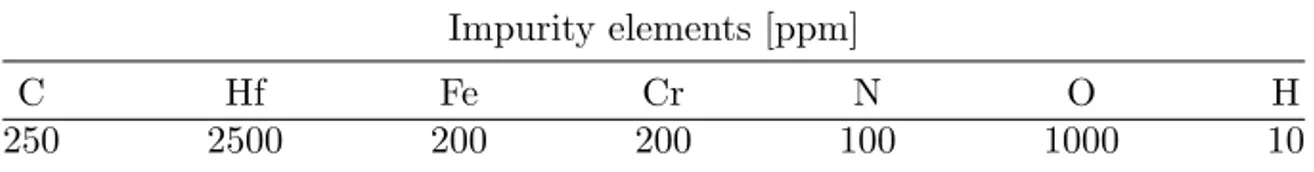
The commercial grade pure zirconium powder (99.2 wt.% purity) with a maximum particle size of about 45 µm is used for the investigations. The detailed nominal composition of the sample is shown in Table 3.1. To avoid oxidation and any other types of contamination, the Zr powder is handled with extreme care under argon environment inside a glove box. The details of sample preparation of each experiment are presented in the respective attached papers.
Table 3.1: Nominal composition of the Zr powder specimens. Impurity elements [ppm]
C Hf Fe Cr N O H
250 2500 200 200 100 1000 10
As described in previous chapters, the formation and stability of different hydride phases are dependent on hydrogen concentration, cooling rate,
stoi-3.5. EXPERIMENTAL DESIGNS 25 1 1.5 2 2.5 d−spacing [Å] Intensity (Normalised) α δ ε γ Normal Direction Transverse Direction (a) 1 1.5 2 2.5 d−spacing [Å] Intensity (Normalised) α δ ε γ Powder RT* Powder RT* rotated 90° (b)
Figure 3.4: Comparison of neutron diffraction patterns of (a) polycrystalline Zr alloy sample on normal and transverse direction, and (b) hydrogenated Zr powder in two different directions.
chiometry, stress state/gradient, alloying elements and impurity. Therefore, to avoid any confusion added by different samples and setups, the same untreated material as received from the manufacturer and hydrogenated with a known concentration has been investigated in different facilities. Furthermore, every setup has been calibrated by using NIST standard samples, LaB6, Si and CeO2.
3.5
Experimental designs
The thermal, high-resolution, multi-array neutron powder diffractometers SPODI at FRM II and Echidna at ANSTO were used for in situ heat treatment stud-ies. The high energy synchrotron X-ray diffraction beam line ID15B at ESRF was used for in situ hydrogen loading studies. These specific beam lines were selected because of their high accuracy with low signal-to-noise ratio, which is ideal for Rietveld analysis [29].
3.5.1
In situ hydrogenation
The experiment has been performed at the ID15B beam line at ESRF. A com-mercial grade, Zr powder with 99.2 wt.% purity, hydrogenated in situ at the beam line by using an on-site high pressure/high temperature capillary system [25, 26]. A fixed high energy, monochromatic X-ray beam with a wavelength λ=0.142352 ˚A and 0.3×0.3 mm beam size was used for probing. A large 2D flat panel detector (Pixium Trixell 4700, Thales) was used for data collection
26 CHAPTER 3. MATERIALS AND METHODS [25, 88]. The details of the hydrogenation and dehydrogenation procedure are described in Paper I, III and IV.
3.5.2
Ex situ hydrogenation
Part of the same Zr powder used in in situ hydrogenation studies was deuterium-charged by a high temperature gas diffusion setup. The loading process was stopped once the desired D and Zr ratio 1:1 was reached. The concentration of deuterium in the system was determined by both mass and pressure changes, and it was found to be 0.9699 and 1.00 by atomic ratio, respectively. The details of the loading setup is presented in Paper II.
3.5.3
Neutron beam line setup
SPODI
Gaseously deuterated Zr powder with 1:1 stoichiometric composition was stud-ied at SPODI in Debye-Scherrer geometry with monochromatic neutrons (λ =1.548211 ˚A). The deuterated Zr powder sample was filled into a vanadium container that measured 40 mm long and 13 mm in diameter with a wall as thin as 0.15 mm under an argon environment in a glove box. Thereafter, the sealed sample container was mounted into a vacuum high-temperature furnace available at the beam line. To ensure quality of the data refinement, each mea-surement was acquired with 40 steps (∆(2θ) = 0.05◦) with several overlaps and 300 000 counts. The details of the beam line, setup and heat treatment are described in Paper II.
Echidna
Part of the same deuterated Zr powder used at SPODI was studied at Echidna in Debye-Scherrer geometry with monochromatic neutrons (wavelength 2.44 ˚
A, and 1.62 ˚A). The powdered sample was enclosed into a cylindrical vana-dium container of 8 mm inner diameter, and approximately 80 mm in length. Then, the system was put into a cryo-furnace and series of diffraction patterns were collected while going through different subsequent thermal cycles in the temperature interval 17-490◦C. Data was acquired in the 2θ range 0-160◦ with steps of 0.05◦. The details of the beam line, setup and heat treatments are described in Paper V.
3.5.4
Lab X-ray setup
The conventional lab X-Ray diffraction experiments were performed on the STOE diffractometer at the Division of Polymer & Materials Chemistry, Lund University, in transition mode with copper radiation (λ=1.540598 ˚A) and scanned in 2-90◦ range in 2θ. For these measurements, the same deuterated Zr powder
3.5. EXPERIMENTAL DESIGNS 27 as was used in the neutron diffraction studies was heat treated at 286◦C and 500◦C with different cooling/heating rates and holding times were used. The details of beam line, setup and heat treatment are described in Paper II and IV.
Chapter 4
Structural analysis
As described in the previous chapter, the diffraction patterns are the unique identities of crystalline materials, at least in theory. However in practice, be-cause of sample preparation, data collection, absorption, thermal vibration, data handling, internal/external strain, mixed phases, impurity and defects in the material, most of the time measured patterns do not correspond to any reported database entries. Hence, after collecting diffraction data researchers have to take all the factors that possibly influence the crystal structure of the target material into consideration before making any conclusions. The way from the first estimated structure model of the crystal to the final accurate model, after including all the corrections, is called structure refinement. As the name suggests, structure refinement is not a structure solution. In this strategy, the approximated model of the structure is refined by strategically introducing various factors into the mathematical structure model so that the diffraction data calculated from the theoretical structure models have close re-semblance to the observed data. There are several approaches that exist for refinement of crystal structures from diffraction data, such as LeBail, Pawley and Rietveld refinement [27–29]
The chapter gives a short introduction about Rietveld refinement and de-scribe the data analysis procedures implemented in the present research.
4.1
Rietveld refinement
Diffraction patterns of polycrystalline samples (e.g. Fig. 4.1a) normally contain two or more phase contributions that have partially or completely overlapping diffraction peaks, as shown in Fig. 4.1b. Using the total integrated intensities of the separate groups of overlapping peaks in the refinement of structures may lead to some information loss. This problem can be overcome by the use of measured profile intensities directly in the refinement procedure instead of
30 CHAPTER 4. STRUCTURAL ANALYSIS the integrated quantities [89], and this can be accomplished by the Rietveld method.
Figure 4.1: (a) A measured diffraction pattern (blue) of the Zr powder at room temperature after hydrogen charging with its Rietveld refinement result (red). (b) Magnification of the enclosed region in (a) which shows the deconvolved single phase curves of the fit.
The Rietveld refinement is a powerful structure refinement method, which was first introduced by Hugo Rietveld in 1967 [29], and now has become an important method for structural analysis of nearly all classes of crystalline materials. In this approach, the calculated diffraction profile from a crystal structure model is compared to the observed profile, and a non-linear least square refinement is used to minimize the difference between these two pro-files by adjusting various refinable model parameters. The quantity minimized therefore is in this general form:
∆ =X
i
Wi{Yi(obs) − Yi(calc)}2, (4.1)
where Yi(obs)= observed intensity at the ith measurement step, Yi(calc) =
calculated intensity at the ithstep, and W
i= weight attributed to each
obser-vation.
Compared with other whole pattern fitting methods, like Pawley and LeBail, in the Rietveld method the integrated intensities are included into all calcula-tions as funccalcula-tions of relevant instrumental, specimen and structural parameters. This is fundamentally different from both the method by Pawley, in which the
4.1. RIETVELD REFINEMENT 31 integrated intensities are regarded as free least square variables, and that by LeBail, in which integrated intensities are determined iteratively after each refinement cycle [27, 29].
A successful Rietveld refinement requires a reasonable initial approximation of many free variables. These usually include peak-shape parameters, zero shift error, unit cell dimensions and coordinates of all atoms in the model of the crystal structure. Other unknown parameters, such as background, scale factor, atomic displacement, etc., may be simply guessed at the beginning, and then effectively refined as the refinement converges to a global minimum. These important refinable model parameters can be summarized into two distinct groups as listed in Table 4 in the appendix.
The peak positions and shapes of the diffraction patterns are mainly defined by instrument and geometry related parameters, and the intensity is mainly defined by structural and phase related parameters. Commonly used refinable parameters are tabulated in Table 4 in the appendix. Because of the high correlation between various model parameters in the Rietveld method, there will be instant divergence if too many non-linear variables are refined simul-taneously or in the faulty order with a incorrect combination. Therefore, it is important to perform refinement in sequential order from the most linear and stable parameters to non-linear and less stable parameters. The best known Rietveld refinement strategy/sequence is suggested by Young [29].
In the Rietveld method, the residual function, ∆ in Eq. (4.1), is minimized through adjusting refinable parameters until it converges and achieves the best fit. In order to measure the process of convergence and evaluate the quality of the fit, it is useful to have statistical agreement factors (fitting criteria). In addition, several criteria have been developed for such purposes and are commonly known as “R-values”. The most commonly used fitting criteria are [27, 29]: Rp= P |Yi(obs) − Yi(calc)| P Yi(obs) (R − profile) (4.2) Rwp= { P Wi(Yi(obs) − Yi(calc))2 P WiYi(obs)2 }1/2 (R − weighted profile) (4.3) Rexp= { (M − P ) P WiYi(obs)2 }1/2 (R − expected) (4.4) GOF = chi2= {P Wi(Yi(obs) − Yi(calc))
2
M − P }
1/2 (Goodness of fit)
(4.5) where M is the number of observations (data points) and P is the number of parameters. Since a simple sum of all differences relative to all observed values
![Figure 2.3: Binary Zr-H phase diagram based on data provided in [3] (Reported metastable phases are enclosed in dashed rectangles).](https://thumb-eu.123doks.com/thumbv2/5dokorg/4109542.86909/32.892.221.677.453.815/figure-binary-diagram-provided-reported-metastable-enclosed-rectangles.webp)
![Figure 3.2: (a) X-ray penetration depth and photon energy relation of few selected engineering materials [87]](https://thumb-eu.123doks.com/thumbv2/5dokorg/4109542.86909/41.892.127.761.528.883/figure-penetration-photon-energy-relation-selected-engineering-materials.webp)