A moving boundary model for fatigue corrosion
cracking
A. P. Jivkov
Solid Mechanics, Malmˆ University, Sweden.
Abstract
Fatigue corrosion crack initiation and propagation is modelled as a moving boundary value problem. The model is based on three physical processes operating at the solid-environment interface ñ material dissolution, passive film formation and surface straining. The dissolution triggers boundary advancement. The rate of boundary advancement depends on the passive film damage caused by the surface straining. Plane edge cracks, nucleating from surface irregularities, are considered. The cracks obtain realistic geometrical shapes where the near-tip region is an integral part of the crack surface. Elastic-perfectly plastic materials are considered and a low-cycle fatigue load is assumed. The problem is solved using a FEM based program and procedures for moving boundary tracking and interior re-meshing. A crucial ingredient of the boundary tracking is the evolved surface re-meshing, where a scheme based on length and curvature constraints is utilised. The work studies how the choice of these constraints influences the results for crack surface evolution. It is shown that characteristic length parameters in crack nucleation and short crack growth depend on the choice of the constraints. It is concluded that an additional physical process operating at the surface has to be accounted for in order to describe the length scales observed in reality.
1 Introduction
Fatigue is one of the physical processes leading to materials degradation and failure of structural components. This process is associated with crack propagation. Aggressive environments introduce corrosion, which in synergy with the fatigue load further deteriorates the material and shortens the life of
structural members. A widely used hypothesis for environment assisted crack growth is that of dissolution, which is localised at the surface region where the material experiences the highest strains, e.g. Parkins [1] and Turnbull [2]. This hypothesis is related to the existence of a passive surface film controlling the access of the solution to a bare metal surface. The film covers the crack surface at rest. The role of the mechanical loading is thought of as damaging the film and exposing a region of bare metal for dissolution. An adsorption process, called repassivation, continuously restores the ruptured film. Thus, the interaction between the loading and the repassivation defines the balance necessary for strain and dissolution localization in the crack tip region. Heldt & Seifert [3] have recently shown that active loading is an essential prerequisite for continuing corrosion cracking, which is a strong support for the key role of the deformation-film interaction. Fatigue loading is an example of such active loading. Mechanistic models by Ford [4] and Engelhardt et al. [5] based on localised dissolution hypothesis assume corrosion crack growth, where a single parameter such as the crack tip opening displacement, or the stress intensity factor is determining all the features from a solid mechanics perspective. It must be recognised in this respect, that corrosion cracks observed in reality do not have atomically sharp tips, but rather look like long slender notches. Hence they possess intrinsic length parameters, e.g. the crack width and the radius of curvature at the tip. Jivkov [6] proposed a model for strain-driven corrosion growth of cracks with such realistic geometries. The results have shown that the local geometry at the tip strongly affects the corrosion crack growth rate. This means that the single parameter description of the mechanistic models [4,5] is not sufficient. Jivkov [7] suggested later that the same mechanism of strain-driven dissolution is responsible for the nucleation of cracks from surface pits. This issue is worth studying because crack nucleation and short crack growth may be the life determining phases in fatigue corrosion. Pitting has been found to be a major mechanism for crack initiation and as a rule the largest pits were responsible for the emergence of cracks, e.g. Kondo [8] and Rokhlin et al. [9]. The present work poses a moving boundary problem to study corrosion cracks evolving from surface pits. A numerical solution to the problem is proposed, based on the finite element method and on a heuristic procedure for moving boundary tracking.
2 Corrosion-deformation interaction
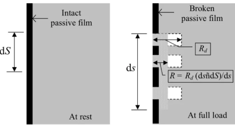
This section describes briefly the physical settings of the model. A surface of a solid body is considered to be in contact with a corrosive environment and initially covered by a passive film. The film is assumed to have the same mechanical properties as the bulk material of the body both in compression and in tension up to a characteristic strain level ñ the rupture strain of the film, given by Engelhardt et al. [5] as εf = 8÷10×10-4. The metal-oxide composition of the passive films justifies this brittleness under tensile strains. The film thickness does not enter the formulation. A segment of the film-covered solid surface is illustrated in Fig. 1, where dS and ds are the lengths of a differential surface
element before and after a mechanical deformation, respectively. This deformation is measured by the strain parallel to the surface, ε = (ds - dS) / ds. Upon load application during one load cycle the film deforms together with the bulk. If the strain at a number of surface points reaches the rupture strain, εf, the film breaks at these points and a corresponding number of film fragments separated by gaps of bare metal are created. The film fragments are then supposed to fully relax. The unprotected gaps are exposed to the corrosive environment and the metal dissolves, advancing that portion of the surface. The dissolution occurs normally to the surface. The rate of the dissolution process depends on the simultaneously operating repassivation process. In a short time the latter restores the film properties of an intact film, i.e. interrupts the active dissolution [1-5]. The repassivation time may vary from a few seconds to a few minutes, depending on the solid-environment composition. The time dimension of the problem, however, is not of interest in this work. Therefore, the cycle period of the fatigue load is assumed to be sufficiently large to allow full restoration of the film before the next cycle is applied. The advance per load cycle in every gap formed along the film-covered surface is assumed constant, denoted by Rd in Fig. 1. A continuum surface advance may be determined by ì smearingî the advances in the gaps over the deformed length of the differential element, as shown in the figure, R = Rd ε. Summarising the above considerations, the advance of a surface point during one load cycle is suggested proportional to the surface strain, ε, via
(
f)
d ε R R= εθ ε− , (1)where θ (x) is the Heaviside step function, i.e. θ (x) = 1 if x > 0, and θ (x) = 0
otherwise.
ds
Broken passive filmdS
At full load Intact passive film At rest Rd R = Rd (dsñdS)/dsFigure 1: Illustration of film rupture, ì trueî dissolution in the gaps (in white) and ì smearedî dissolution over the surface element ds (shaded).
3 Problem description and general solution method
The problem is stated for a plane body occupying the region 0 ≤ X1 ≤ B and X2 ≤ B with respect to a fixed coordinate system (X1, X2). The surface of the body at X1 = 0, X2 ≤ B is in contact with a corrosive environment and initially covered by a passive film. The rupture strain of the passive film is chosen as εf = 0.001. A pit of width W = 10-3B and depth D = 10-4B is introduced on the contact surface.
Fig. 2 illustrates the geometry of the near-pit region. The material of the body is chosen elastic-perfectly plastic with Youngís modulus E = 206 GPa, Poissonís
ratio ν = 0.3, and yield strength σy. The body is considered to be in plane strain. If the components of the displacement and the traction vectors are denoted by U1
and U2, and T1 and T2, respectively, the boundary conditions for one load cycle
are given as follows: T1 = T2 = 0 and eqn (1) along X1 = 0 (including pit surface);
U1 = T2 = 0 along X1 = B; T1 = 0, U2 = u along X2 = B; T1 = 0, U2 = -u along X2 =
-B, where u is the applied peak displacement during the cycle. The peak
displacement is chosen as u = εf B, which ensures a constant strain field in a rectangular body without surface flaws and is exactly on the threshold to break the protective film of the flat surface.
The problem stated above constitutes a moving boundary value problem (MBVP), where each load cycle is understood as a new boundary value problem. The new problem geometry is determined by the entire past history of the evolving boundary. The equilibrium solution for the new problem defines the present evolution. A numerical solution for the MBVP, proposed here, is based on a problem split into equilibrium and evolution parts over each load cycle. The equilibrium part is solved using the commercial finite element analysis program ABAQUS [10]. Constant strain triangular finite elements are used in the analysis. The surface strains, ε, obtained at equilibrium, provide the advance of the corroding surface via eqn (1). By displacing the corroding surface to its evolved position the current geometry is changed and the boundary value problem for the next cycle is prepared. In the finite element environment, the
X1 X2 W E, ν, σy D = 0.1W Figure 2: The near-pit geometry.
surface advance is represented by surface node displacements. In order to properly follow the surface shape changes, a new distribution of nodes along the evolved surface is essential. This issue is addressed in the next section. The evolved body geometry requires re-meshing of the interior, which is completed with a Delauney-type triangulation procedure following Shewchuk [11].
4 Moving boundary refinement
The existing nodes along the evolving surface at the beginning of a load cycle, define via eqn (1) the positions of the same number of points along the advanced surface at the end of the load cycle. A B-spline curve is created along the new surface using these points as spline knots. The nodes along that curve are distributed using a surface refinement process, based on one curvature and two length constraints. At every step of the surface refinement process, the nodes already introduced form a polygon of line segments. The curvature constraint is given by the maximum angle, γ max, that two neighbouring segments are allowed
to make. The length constraints specify the maximum and the minimum allowed node spacing and are denoted by emax and emin, respectively. The maximum node
spacing is used to initially distribute nodes along the B-spline at regular distances. After this initial meshing, the refinement procedure is based on segment splitting using the maximum angle and minimum distance constraints. Fig. 3 illustrates the refinement of a segment si, enclosed between the existing nodes, ni and ni+1. The curve described by the B-spline is shown with a dotted line while the existing line segments are drawn with full lines. Firstly, the length of the current segment, denoted by ei, is checked against the minimum allowed node spacing. If ei < 2 emin the segment is accepted as not requiring further
refinement. Otherwise, the position of the point along the B-spline, lying midway between ni and ni+1 is calculated. This point is shown with an unfilled circle in the figure. The two potential segments, connecting the introduced point with the existing nodes are shown with dashed lines. The oriented angle between
s
i, e
iγ
in
in
i+1New node
Figure 3: Illustration of the surface refinement process.
them is denoted by γi. If γi < γmax the current segment does not require further
refinement, since the curvature criterion is met. If γi ≥ γmax the unfilled point is
introduced as a new node along the surface, and the dashed segments become newly accepted parts of the boundary polygon. The procedure runs over all currently existing line segments and terminates when there are no more line segments, requiring refinement.
5 Results
During all numerical simulations the condition emax = 10emin has been
maintained. A normalised load factor, σ∞ /σy, is introduced, where the remotely applied stress is σ∞ = Eεf for the given boundary conditions. Three different series of simulations have been performed. Firstly, minimal element sizes in the interval 10-3 ≤ e
min / W ≤ 10-2 have been tested with fixed values σ∞ /σy = 0.25 and tan(γ max) = 0.15. Secondly, simulations for a series of maximal angles given
by 0.07 ≤ tan(γ max) ≤ 0.21 have been performed with σ∞ /σy = 0.25 and emin =
5×10⁻³W. Thirdly, a number of yield strengths such that 0 ≤ σ
∞ /σy ≤ 0.5 have been tested with emin = 5×10⁻³W and tan(γ max) = 0.15.
A typical crack evolution for emin = 5×10⁻³W, tan(γ max) = 0.15, σ∞ /σy = 0.25 is shown in Fig. 4. The profiles of the initial pit, the surface at crack incubation (to be shortly defined), and the crack at extension W are presented. The current
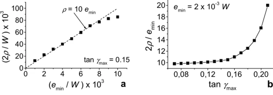
crack length is denoted by a. The crack width in the tip region, 2ρ, is defined as the distance between the points where 45° lines running back from the crack tip intercept the crack faces. The crack width attained at incubation was found to be independent of the material yield strength (as a result of the third simulation series) and of the initial pit geometry. The latter is demonstrated in Fig. 5, which represents the results of the first two simulation series ñ ρ vs. emin (a) and ρ vs.
γ max (b). The attained incubation crack width was found to be 2ρ ≈ 10emin. For
sufficiently small maximum angle constraint, e.g. γ max < 9° for emin = 2×10⁻³W,
W a ≈ W 2ρ ainc ≈ 10ρ D = 0.1W
Figure 4: Typical crack morphology evolution.
ρbecomes independent of that constraint. The same independence of the initial geometry and material yield strength was found for the crack extension at incubation, ainc ≈ 10ρ as depicted in Fig. 4.
The stress intensity factor, KI, for a corresponding sharp crack emerging from a surface pit is written as:
(
a DW)
f a KI =σ∞ π , , , (2) where f(a, D, W) is a geometry factor, that may be found in e.g. Tada et al. [12]. Fig. 6 shows the development of the normalised crack growth rate, (R / Rd) tip = ε tip, as a function of the stress intensity factor, eqn (2), for the case presented in Fig. 4 and at two scales ñ around the incubation point (a) and during all stages of the subsequent evolution (b). The stress intensity factor is normalised with the material yield strength and the square root of the crack width, attained at incubation. For a long slender notch such as the corrosion crack of Fig. 4, a proportionality between KI /(σy√ρ) and the strain at the tip, ε tip, reveals theexistence of a KI -controlled zone surrounding the tip [12]. This helps to define
the crack incubation point as the onset of a linear relation between crack growth rate and KI, Fig. 6(a). This is also the point where the evolving pit surface attains the width 2ρ, which is maintained nearly constant during the first stage of propagation shown in Fig. 6(b) and called short crack growth. An end of short crack growth may be defined as the point where large plastic deformations cause initially sharpening of the tip region. This changes the acceleration of the corrosion crack, but later leads to crack tip blunting, which continues until the crack tip region attains a shape that is maintained self-similar during the remainder of the evolution. The self-similar geometry is such that all strains along the surface in the tip region are kept constant while that region expands as a void. Therefore, this growth is characterised by an approximately constant rate. As already mentioned, the results of the third series of simulations (variable material yield strength) have shown independence of the crack width with respect to σy. What the yield strength affects is the profile of the crack tip region, 0 2 4 6 8 10 0 20 40 60 80 100 tan γmax = 0.15 ρ = 10 emin a (2 ρ / W ) x 10 3 (emin / W ) x 103 0,08 0,12 0,16 0,20 10 12 14 16 18 20 emin = 2 x 10⁻³ W b 2 ρ / emin tan γmax
which changes from a nearly circular shape for elastic or very hard plastic materials, i.e. σ∞ /σy → 0, to a sharper profile for softer plastic materials. This
may lead to about two times larger strains at the tip for soft materials, σ∞ /σy → 0.5, which means two times faster propagation in the short crack region. Detailed presentation of these results is given elsewhere by Jivkov [13].
6 Discussion and conclusions
The present study aimed at modelling nucleation and propagation of fatigue corrosion cracks as a moving boundary value problem. Three basic processes ñ deformation, dissolution and repassivation ñ have been accounted for when describing the model in section 2. It is clear from this description, that these
0,0 0,4 0,8 1,2 1,6 2,0 0,000 0,003 0,006 0,009 0,012 0,015 a KI-controlled growth Incubation R / Rd KI / (σy√ρ)
0 1 2 3 4 5 6 7 8 0,00 0,02 0,04 0,06 0,08 0,10 b Non-linear growth (large strains) Const ant ra te gr ow th (s e lf-si m ila r sur face evol ut ion) S hor t cr a ck gr ow th In cubat io n R / Rd KI / (σy√ρ) Figure 6: Crack growth rate development during (a) incubation and onset of linear growth; (b) all stages of evolution.
processes cannot introduce a length parameter into the problem. The only length scale is initially established by the width of the existing pit. The proposed numerical solution of the problem is based on a moving boundary tracking procedure, which uses constraints for element size and curvature. These constraints introduce an additional non-physical length scale. The results presented in Fig. 6 show that the crack width attained at incubation to a large extent controls the corrosion crack behaviour. This crack width, however, was found to be independent of the initial pit geometry. Fig. 5 suggests that the forming crack tends to minimise its width as much as the numerical constraints allow. This may be considered as a valuable feature of the moving boundary approach, because it leads to corrosion cracks attaining realistic geometrical shapes and allows the study of their evolution. In a limit, however, the observed trend would produce a crack with atomically sharp tip. In reality there must be a physical reason for the established crack width that has not been taken into account in the model. One reason may be the material microstructure where the grain boundary thickness might be the determining length parameter. Another possibility is that an additional physical process operating on the solid surface is counteracting the observed tendency for shrinking. A candidate physical process is the diffusion of atoms along the solid surface. It has been previously shown that stress-driven surface diffusion of atoms may lead to morphology evolution of solid surfaces, e.g. Freund [14]. While the interaction between the surface deformation and the dissolution and passivation processes tends to minimise the forming crack width, the surface diffusion tends to operate in the opposite direction by bringing material particles from less to more strained surface regions. One may only speculate at present, that the balance between these two tendencies determines the size of the nucleated crack, since the role of the surface diffusion increases with the increasing surface strains in the tip region. Further, one may speculate that the same balance is in reality not allowing the corrosion cracks to blunt and grow self-similarly, as was the result of the present work during the non-linear growth stage.
Despite the insufficiency of the suggested physical model, the moving boundary formulation proved to be effective in studying the nucleation and propagation of corrosion cracks. The results clearly show the importance of the deformation-corrosion interaction for strain and dissolution localisation during crack incubation. The end of incubation is marked by the appearance of a controlled zone surrounding the crack tip. The propagation interval under KI-control is called short crack growth. This is a fully autonomous growth governed by the crack width attained at incubation. A stage, characterised by large deformations in the tip region succeeds the short crack growth. In this non-linear regime, crack tip blunting and self-similar growth are then observed. It must again be emphasised that the discovered autonomy of the crack growth from the initial geometry yields the necessity of an additional physical phenomenon that would introduce the missing length scale. It is believed that results of an improved physical model will show qualitatively the same behaviour of a corrosion crack emerging from a surface pit, at least during the first three stages of corrosion crack evolution shown in Fig. 6.
Acknowledgments
The financial support of the Swedish Centre for Nuclear Technology (SKC) and the Knowledge Foundation (KKS) is highly appreciated.
References
[1] Parkins, R.N., Current understanding of stress-corrosion cracking.
Journal of Metals, 44(12), pp. 12-19, 1992.
[2] Turnbull, A., Modelling of environment assisted cracking. Corrosion
Science, 34(6), pp. 921-960, 1993.
[3] Heldt J. & Seifert, H.P., Stress corrosion cracking of reactor pressure vessel steels under boiling water reactor conditions. Proc. of the 9th Int.
Symp. on Environmental Degradation of Materials in Nuclear Power Systems ñ Water Reactors, eds. F.P. Ford, S.M. Bruemmer, & G.S. Was,
The Minerals, Metals & Materials Society (TMS), pp. 901-910, 1999. [4] Ford, F.P., Quantitative prediction of environmentally assisted cracking.
Corrosion, 52(5), pp. 375-395, 1996.
[5] Engelhardt, G.R., Macdonald, D.D. & Urquidi-Macdonald, M., Development of fast algorithms for estimating stress corrosion crack growth rate. Corrosion Science, 41(12), pp. 2267-2302, 1999.
[6] Jivkov, A.P. & StÂhle, P., Strain-driven corrosion crack growth ñ a pilot study of intergranular stress corrosion cracking. Engineering Fracture
Mechanics, 69(18), pp. 2095-2111, 2002.
[7] Jivkov, A.P., Evolution of fatigue crack corrosion from surface irregularities. Theoretical & Applied Fracture Mechanics, in press, 2003. [8] Kondo, Y., Prediction of fatigue crack initiation life based on pit growth.
Corrosion Science, 45(1), pp. 7-11, 1989.
[9] Rokhlin, S.I., Kim, J.-Y., Nagy, H. & Zoofan, B., Effect of pitting corrosion on fatigue crack initiation and fatigue life. Engineering
Fracture Mechanics, 62(4/5), pp. 425-444, 1999.
[10] ABAQUS Userís Manual, Version 6.3, Hibbitt, Karlsson & Sorensen Inc., 2002.
[11] Shewchuk, J.R., Delaunay refinement algorithms for triangular mesh generation. Computational Geometry, 22(1-3), pp. 21-74, 2002.
[12] Tada, H., Paris, P.C. & Irwin, G.R., The stress analysis of cracks
handbook, 3d Ed. ASME Pres: New York, 2000.
[13] Jivkov, A.P., Surface irregularities as sources for corrosion fatigue. Proc.
of the Int. Conf. on Computational Mesomechanics, Tokyo University:
Tokyo, in press, 2003.
[14] Freund, L.B., Evolution of waviness on the surface of a strained elastic solid due to stress-driven diffusion. International Journal of Solids &