Scientific Press International Limited
Dam Safety: Technical Problems of
Ageing Concrete Dams
Nasrat Adamo1, Nadhir Al-Ansari2, Varoujan Sissakian3, Jan Laue4 and Sven Knutsson5
Abstract
Concrete dams age as all man-made structures. Being subject to various external influences and internal reactions their ability to withstand them diminishes with time. Description of these factors are given here. The manifestations of aging signs are cracking, expansion, spalling and scaling of concrete surfaces, change of color and efflorescence, gelatinous discharge, crumbling of concrete masses, in addition to abrasion and cavitation of surfaces. The mechanisms of the actions leading to these damages are described and supported by many examples and case studies. The general conclusion drawn is that nothing can be made to extend the lives of old dam indefinitely, but a lot can be done to elongate their useful service with repair and upgrading works until technical considerations prove them unfeasible or their cost become prohibitive.
Keywords: Dam Aging, Cracking, Expansion, Spalling, Scaling, Abrasion,
Cavitation.
1 Consultant Dam Engineer, Sweden.
2 Lulea University of Technology, Lulea, Sweden.
3 Lecturer, University of Kurdistan Hewler, and Private Consultant Geologist, Erbil. 4 Lulea University of Technology, Lulea, Sweden.
5 Lulea University of Technology, Lulea, Sweden.
Article Info: Received: June 9, 2020. Revised: June 18, 2020.
1. General
Aging of concrete dams may result from both physical and chemical factors. The former relate to changes in forces acting on the structure, including those caused by temperature variations, settlement, earthquake vibration, blocked drainage, or relief wells. The latter are associated with infiltration of aggressive waters containing inorganic acids, sulfates, and certain other salts into the dam body or its foundation. Chemical reactions of these substances with constituents of concrete can result in its leaching and disintegration or expanding followed by cracking and spalling. Soft water, for example, may attack concrete causing serious damage by freezing and thawing within few years. Defective or inferior materials used in the construction of a concrete dam can result in deterioration and possible failure of the structure. Poorly bonded cement, weak aggregates, or mineral-laden water can produce low-strength concrete. Highly absorptive aggregates may be susceptible to freeze-thaw damage. Aggregate contaminated by soils, salts, mica, or organic material, also may produce substandard concrete. Concrete mixes for massive structures usually contain air-entraining agents which appreciably improve the durability of the concrete and increases resistance to freezing and thawing. Yet, distress still can occur where entrainment is insufficient or when the aggregate itself is vulnerable to freeze-thaw action. Closely spaced parallel cracks at edges of concrete blocks in gravity dams may be symptomatic of freeze-thaw expansion. Entrance of water into the cracks and subsequent freezing are likely to further the deterioration.
In summary, disintegration of concrete may be caused by freezing and thawing, thermal expansion, and contraction, or wetting and drying. Freeze-thaw effects are most likely to be found in parapets, cantilever beams, slabs, and walls of appurtenant structures. All the above reasons contribute to weakening the structure, being a concrete dam or any other concrete hydraulic structure and cause its aging. Dam settlement and cracking of aged concrete structures may be attributable also to external physical factors such as uplift, foundation displacements, ice thrust, or seismic forces. Such factors and their impacts on dams are well documented in technical literature especially in dam failures and accidents study cases over the last century. Intrinsic physical factors which play in negative fashion to dam safety are those causing wear and tear to the concrete materials of the dam and its hydraulic steel structures.
Outlet structures and spillways may suffer appreciable damage by the abrasion of debris impacting on concrete surfaces in high floods degrading these structures. In spillways or outlet works conveying high velocity flows, offsets in the conduit surfaces may cause cavitation. Moreover, vibration of structures by earthquake, water surges, or equipment operation may damage concrete. Damage due to the overstressing of a concrete dam often is identified by examination and careful observing of clues which include cracking, opening at joints or lift surfaces, seepage variations, and displacements. Erosion of concrete may be caused also by flowing ice, sediments, logs, wind, traffic, or cavitation.
of drainage systems. The need for regular maintenance of drains is well recognized. Obstruction of dam’s foundation drains may be attributable to various causes, including displacement, soil or rock deposits, biological growth, and leaching and deposition of chemical [1].
2. Deterioration of Concrete in Old Concrete Dams
Deterioration of many old concrete dams which have outlived their usefulness, or become safety hazard, has been attributed in many cases to the chemical reaction of the constituents of cement and aggregates making up the concrete in the presence of water over a long period of time. A typical example of such reaction is the Alkali-Aggregate Reaction (AAR). Such chemical process is evidenced in upstream movement of an arch dam crown, spalling of the concrete at extremities, and by characteristic pattern cracking and crazing of the dam face. The strength of the concrete mass may be reduced by alkali-aggregate reaction also.
Visible clues to such deterioration include: 1. Expansion.
2. Cracking of random pattern. 3. Gelatinous discharge.
4. Chalky surfaces.
Petrographic examinations of the concrete cores taken from affected structures have revealed severe fracturing and tests have also shown a strength reduction as much as 25% or more.
Expansion in the decomposing concrete can be substantial, but rates of movement usually appear to decrease as the dam increases in age. Alkali-aggregate reaction sometimes causes the disbonding of blocks at lift surfaces. Loss of strength by disbonding, and the accompanying increase in hydrostatic pressure along the lift surfaces will reduce resistance to sliding and overturning. Alkali-aggregate reaction can cause expansion of a concrete dam with consequent cracking and deterioration of valves and metalwork and possible binding of gates into their guides.
Once alkali-aggregate reaction has developed in a relatively thin concrete dam, it cannot be stopped practically by any means known. Where deterioration has progressed to a dangerously advanced stage, the effective remedies are to remove and replace the defective concrete or to build a new dam to replace the old one. Otherwise there will come a time when the dam is unable to withstand either static and/or dynamic flood induced loads, or earthquake loadings leading to catastrophic failure. As such dam weakens, the probability of an adverse response to a given load increases. The case of “Clear Creek Dam” may be cited here for illustration.
2.1 Clear Creek Dam Case
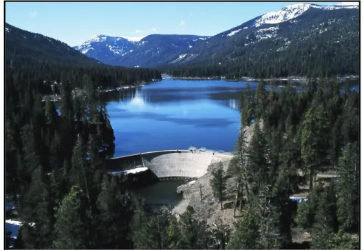
This concrete thin-arch dam was originally completed in 1915 by the United States Bureau of Reclamation on the north fork of the Tieton River in Yakima County, Washington State, refer to Figure 1. Height of the dam was 19m and its length was
123m at the crest. In 1918 it was raised by 6.4m to its present height of 25m and it was partially rebuilt in 1964. The dam suffered from a variety of deterioration mechanisms and the concrete properties diminished. Analysis of the dam conditions identified a strong probability of failure under static, hydrologic, and dynamic loading.
Figure 1: Clear Creek dam (Washington) downstream view.
Rehabilitation work in 1964 consisted primarily of: placing new concrete in the arch section between elevation 2991m (a.s.l.) and the crest, repairing cracks and poorly consolidated concrete with neoprene and epoxies, and installing protective wire-mesh fences from the abutments to upstream areas. Resulting from investigations conducted in 1987-1989, the Bureau of Reclamation concluded there were horizontal bands of deteriorated concrete in the section replaced in 1964. These conditions could result in sudden failure of the dam, so early in 1990 the water level of Clear Lake was immediately lowered to reduce the likelihood of dam failure to less than 5% of its design capacity by drilling two holes through the dam to further drain the lake to a point that only 230 acre-feet (283,700m3) could be stored out of the total original capacity of 5,300 acre feet (6,500,000m3). Reconstruction works were accomplished and consisted of converting the dam into a gravity structure by buttressing the arch with a new concrete section immediately downstream. A new 48-inch outlet conduit was installed near the elevation of the breach (2,956.5 feet) to permit discharge whenever the lake was below the spillway crest. Clear Lake which has a water surface area of 260 acres (110ha) is used now primarily for recreation including boating and fishing and most of the discharge is through the spillway [2] and [3].
3. Concrete Deterioration Mechanisms by Chemical Agents
Concrete deterioration is a progressive reduction in properties, which with the passage of time may ultimately make concrete no longer serviceable for its intended use.
This can result from:
i. Physical “removal” of materials from the surface of the structure which may be caused from erosion by debris or cavitation by high velocity flow, leading to a reduced cross section.
ii. An internal change in strength, modulus of elasticity, Poisson’s ratio, or density that reduces its overall structural load-carrying capacity. iii. Surface deterioration and loss of material may be caused by freezing
and thawing (F/T) of concrete which leads to a reduced cross section of a concrete dam. The reduced cross section increases the stresses of the remaining section proportionately to the amount of material
removed. Internal change in strength, and other mentioned properties that reduces overall
structural load-carrying capacity of a concrete structure can be caused by Alkali- Aggregate Reactivity (AAR) or Sulfate Attack in processes which can take long time and their adverse impacts appear after many years of service. Concrete dams and concrete ancillary structures which are expected to have a life span much longer than their assumed life may show signs of such deterioration at late age in a similar way to human beings when potential sources of weakness become active leading to death.
4. Alkali-aggregate reaction (AAR)
This is a reaction in concrete between the alkali hydroxides, which originate mainly from Portland cement, and certain types of aggregate both used in the construction of the structure. Two types of (AAR) are currently recognized; these are alkali-silica reaction (ASR) and alkali-carbonate reaction (ACR). As the names imply, these types of reaction differ in that they involve reactions with either siliceous or carbonate types in the aggregates which lead to volume change and may reduce the strength and modulus of elasticity of the entire structure. Swelling and cracking of concrete outlets or spillways caused by ASR or ACR lead to reduced structural performance, and the cracking may accelerate other deterioration mechanisms, such as freezing and thawing (F/T) deterioration.
Problems due to ASR were first identified in USA in the State of California in the 1930s and reported by Thomas Stanton of the California State Division of Highways in 1940. Stanton’s studies demonstrated that the expansion of mortar bars was influenced by the alkali content of the cement, the type and amount of the reactive silica in the aggregate, the availability of moisture, and temperature. He further showed that expansion was negligible when the alkali content of the cement was below 0.60% Na2Oe and that expansion could be reduced by pozzolans, thus setting
the groundwork for preventive measures. Subsequent to Stanton’s discovery ASR was diagnosed as the cause of abnormal cracking in a number of dams operated by the U.S. Bureau of Reclamation, such as the Parker Dam in Arizona. So, a number of agencies in USA initiated studies on ASR in the 1940s, for example; the Army Corps of Engineers, Bureau of Public Roads, Portland Cement Association. Other countries followed such as Denmark and Australia. ASR is now recognized as a major cause of concrete deterioration in dams in the world that has incidents in many States in USA and also in numerous countries worldwide [4].
Stanton studies in 1940 opened the way to the use of pozzolans for reducing the harmful effects of ASR and this was first put into practice in the same decade when calcined clay was used to prevent it in the Davis Dam constructed between 1942 and 1950. The reaction was implicated as the cause of cracking in the Parker Dam, which was completed shortly before construction began on the Davis Dam and is located 141km upstream of Davis Dam on the Colorado River. Ten years after Stanton’s (1940) discovery the potential for using fly ash and slag for controlling expansion was first documented, and it is now widely accepted that supplementary cementing materials are an effective means for controlling ASR expansion.
History of several US Bureau of Reclamation old structures shows that many of them experienced damage due to this reaction. Beginning in the mid-1920s. The Bureau did not fully understand the causes of the deterioration at the time. Some of the notable dams suffering from it include; American Falls (Idaho), Owyhee (Oregon), Seminoe (Wyoming), Friant (California), Parker (Arizona), and Stewart Mountain (Arizona). Typical deterioration included swelling and cracking of the concrete, accompanied by a decrease in strength and modulus of elasticity. The cracking also provides avenues for moisture to enter the concrete and contribute to accelerated (F/T) attack in cold climates.
Methods to prevent ASR were developed by 1942 which included identifying potentially reactive aggregates using petrographic techniques, limiting their use, and specifying low-alkali cements and pozzolans [5].
For further elaboration on ASR problems on dams, two study cases are considered here for further explanation:
i. The American Falls Dam (Idaho). ii. Seminoe Dam (Wyoming). iii. Pracana Dam in Portugal.
4.1 The American Falls Dam (Idaho), Study Case
This dam, which was completed in 1927, is a 94-foot-high composite concrete and earth gravity-type dam on the Snake River near American Falls, Idaho, which holds a storage capacity of 1,700,000 acre-feet (2,1x10⁹m3).
Principle benefits of the dam include irrigation, power generation, flood control, fish and wildlife resources, and recreation. During the years following construction, signs of distress appeared on the dam. Core-drilling program in the early 1960s revealed that the concrete in portions of the dam was in a relatively advanced stage of deterioration due to a chemical reaction between alkalis in the cement and the
aggregate (ASR). This type of reaction, unknown at the time of construction, resulted in a significant loss in strength and durability, threatening the competence of the dam and resulting in filling restriction that reduced the storage capacity of the reservoir to about 66% of its maximum design capacity. In 1973, works for construction of a new dam started and it was completed in 1978, while the original structure was demolished. Later on, similar problems appeared in the new dam. A value engineering study that was initiated in 2015 recommended the following corrective actions:
a. Removal and replacement of 6 inches of concrete on the spillway face and stilling basin floor.
b. Repair of concrete on the upper spillway gate operator’s decks and complete replacement of the spillway adits (access entryways).
The study stressed the need for improving the structural integrity of the spillway to avoid further deterioration which could lead to serious structural deficiencies, and provide a more feasible means of access for future maintenance activities. The cracked and damaged state of concrete on the spillway, spillway gate operating decks, downstream dam face concrete, and stilling basin floor structures created strong need for action. These concrete components of the dam structure were exhibiting significant deterioration, cracking, and spalling, and required repair. Minor repairs, however, were already completed to the spillway face throughout its lifetime, including an overlay of the stilling basin floor that was completed in 1978 to repair damaged concrete after the initial spill season. A new study was completed in May 2019 which endorsed the 2015 findings and included an environmental impact assessment study.
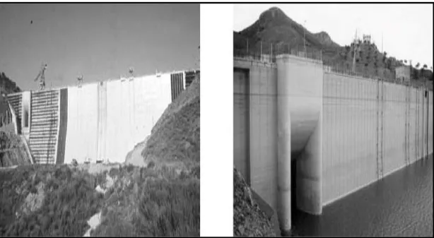
The planned construction activities will take place on the downstream portion of the dam. This project will address the need for replacement and repair of deteriorating concrete on the spillway, spillway gate operators’ decks, downstream dam face, adits, and stilling basin structures, which have experienced degradation over 40 years of service, refer to Figures 2 and 3.
Figure 2: View of the old original American Fall Dam (1927).
Construction activities will consist of the demolition, cutting, removal, and replacement of existing damaged concrete and reinforcing of these components, and replacement or modification of an existing drain grate in the stilling basin. Construction will take place from June to November 2020 and mid-July to November 2021. Examples of the current state of deterioration in this dam are pictured and presented in Figures 4 , 5 and 6 [6].
Figure 4: Disintegrating surface concrete observed on dam face.
Figure 6: Structural deterioration of concrete on spillway gate operator deck. Extensive exposed aggregate is apparent.
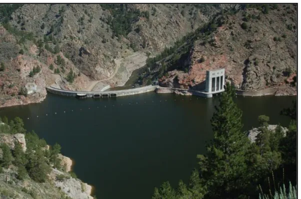
4.2 The Seminoe Dam (Wyoming) Case
Seminoe Dam is a concrete thick-arch dam on the North Platte River in the U.S State of Wyoming. The dam stores water for irrigation and hydroelectric generation, and is owned and operated by the U.S. Bureau of Reclamation.
The 295-foot (90m) dam was constructed in 1939 and forms Seminoe Reservoir, which covers more than 20,000 acres (8,100 ha) when full. The dam is exposed to severe winter conditions, fairly rapid and extreme temperature changes, and frequent freeze-thaw cycles. A few years after construction some cracking, and deterioration of the concrete was observed. This was at a time before the discovery that low alkali cement, air entraining admixtures, and other beneficial modifications to concrete could ameliorate deleterious chemical and physical deterioration.
Downstream and upstream views of the dam are shown in Figures 7 and 8. Cracking and deterioration of concrete was chiefly observed along the upper parapet walls and power house walls. Although since the 1950s, ASR was suspected of causing some of the cracking visible at the top of the dam, ASR did not appear to be a major concern. In 1951, a petrographic examination of the concrete revealed indications of ASR along with freeze-thaw deterioration. It was not certain whether ASR or freeze-thaw deterioration was the main cause for this deterioration. The examination revealed the presence of about 4.5% reactive particles, chiefly cherts, andesites, and rhyolites, which were judged to be only marginally deleterious.
Figure 7: Downstream view of Seminoe Dam.
Part of the reason of this uncertainty was that petrographic examination indicated that a potentially deleterious reaction was unlikely based on the composition of the aggregate particles and tests for reactivity. At this time, most experience with ASR indicated the reaction showed up fairly early in the life of the structure and was fairly easy to identify, but these experiences were with more reactive aggregates with structures in warmer climates.
In a 1970’s, petrographic examination and on concrete cores indicated extensive damage to the upper 5 feet with minimal to moderate damage to about 20 feet. In a 1980’s petrographic examination of cores testing indicated extensive damage to the upper 8 feet of concrete and minimal to moderate damage below 8 feet. In the 1990’s several subsequent petrographic examinations showed more indications of alkali aggregate reaction and that the alkali aggregate reaction was continuing. Later examinations indicated the reaction was a slowly reactive form of ASR involving quartzite containing strained quartz, which is known to be a slowly reactive form of silica. In these examinations areas of extensive damage were observed to the upper 18 feet of the dam.
In 2013, a coring program provided fresh cores drilled from five vertically oriented drill holes on the crest. Selected intact core fragments were tested for physical properties and strength conditions, as well as, petrographic analysis to determine the current condition of the concrete. In this 2013 program, evidence of ASR was observed in cores up to 75 feet depth [7].
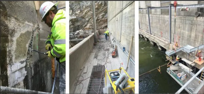
Some concrete repair and stop log replacement project was recently completed at Seminoe Dam. The river outlet works and stilling basin at Seminoe Power Plant was identified to have deficiencies in the concrete located around the outlet works and the tailrace deck. The stop logs were constructed as part of the original Seminoe Dam and Power Plant in 1939 and over 81 years of wear and tear had taken their toll. They no longer provided an adequate seal to allow periodic maintenance of the power plant draft tubes and river outlet gates. The tailrace deck also had deteriorated concrete and the stairway leading to the tailrace deck did not meet accepted standards.
The repair works were started on February 8, 2016, beginning with construction of a cofferdam to protect the work site from flows passing through the power plant. Upon completion of the cofferdam, the work area between the upstream face of the dam and the cofferdam was dewatered. Areas around the damaged concrete that required repair were removed using chipping hammers to the required design depth. New steel reinforcement and concrete was placed in the repair zones. Cracks were sealed using a pressurized epoxy grout system. The contractor completed all of the concrete repairs in the tailrace area protected by the cofferdam by March 23, 2016. The contractor removed the cofferdam from the river by April 6, to allow for
The tailrace deck was resurfaced by saw cutting the surface, using jack hammers to
remove deteriorated concrete, and then adding a new layer of fresh concrete. Photographs of the performance of some of the described works are shown in
Figures 9 and 10 [8].
Figure 9: Left: Injecting epoxy to repair crack. Center: Concrete removal on tailrace deck. Right: Installing new stairway.
A new study by Colorado University at Boulder is underway now, on behalf of the Bureau of Reclamation to study the long term assessment of dams suffering from Alkali Aggregate Reaction. This reflects the concerns of the Bureau over the safety of their great number aging concrete dams, and even ancillary concrete works of their old embankments dams due to this reaction. This study may give some indications on the overall safety of these dams and can open the way to decommissioning of some [9]. Countries other than USA have also suffered of the same problem in their dams, but the discovery of this phenomenon and the extensive work for remedial action was pioneered in USA with extensive volume of research work and documentation.
Figure 10: Repairs in river outlet works center pier showing reinforcing bars and the finished shape.
4.3 The Pracana Dam Case
This is one more case in Portugal this time which can be cited in relation to a novel solution for rehabilitation of a dam suffering from AAR which is that of Pracana Dam. The dam, a 65 m high concrete buttress dam in a seismic region of Portugal, was constructed between 1948 and 1951, refer to Figure 11. In 1980, the dam was taken out of operation to undertake a thorough investigation of the deterioration related to the continuous concrete expansion phenomena. Investigations ascertained the presence of a secondary alkali-aggregate reaction which would be further activated by infiltration of water from the reservoir, creating a critical scenario in respect to sliding conditions along horizontal cracks. Installation of a drained waterproofing liner on the upstream face was deemed necessary to stop water infiltration feeding this reaction and to avoid the possibility of water exerting uplift in the horizontal cracks, especially in the case of a seismic event. The installation of PVC geomembrane was chosen as protective solution and it was completed in 1992. The exposed drained geomembrane system was installed in the dry season of 1992, in 5 months, concurrent with major rehabilitation works including construction of a new foundation beam and grout curtain, two sets of concrete struts on the downstream face, local grouting of larger cracks and mass grouting of smaller cracks, construction of a new spillway and a new water intake. Since 1992, the
behavior of the geocomposite waterproofing system has been monitored in respect of leakage and its capability of dehydrating the dam, reducing the water content feeding this harmful reaction, and to avoid the possibility of water exerting uplift in the horizontal cracks, especially in the case of a seismic event. Two photographs showing the dam during and after rehabilitation work are presented in Figure 11 [10].
Figure 11: Pracana Dam affected by Alkali Aggregate Reaction during and after rehabilitation by water proofing.
In our opinion, this solution remains to prove its credibility after many more years of operation on; first, the durability of the material itself; second the possibility of its use in other situations in dams, and third, the economic feasibility of such installation.
An article published by the Canadian Journal of Civil Engineering in 2011 with the title “Alkali-aggregate reaction in concrete: a review of basic concepts and engineering implications” gives a comprehensive analysis of the Alkali-aggregate reaction problems in concrete structures including the basic concepts of the reaction and expansion mechanism, conditions conducive to the development and sustainability of the reaction in concrete, in addition to the selection of preventive measures and management of structures affected by it [11].
Reference to this paper help the understanding and early discovery of the phenomenon in concrete dams, and on required actions of protection to elongate serviceability of dam under question. A presentation in conference, given by one of the authors of this paper gives more details with explanations and photographs illustrating examples of damage in concrete structures including dams in many
countries [12]. More on this subject may also be found in Portland Cement Association publication by (James A. Farny and Beatrix Kerkhoff “Diagnosis and Control of Alkali-Aggregate Reactions in Concrete”) [13].
In summary, alkali-aggregate reaction on gravity dams and ancillary structures, can sometimes cause the disbonding of blocks at lift surfaces. Loss of strength by disbonding, and the accompanying increase in hydrostatic pressure along the lift surfaces will reduce resistance to sliding and overturning. Moreover, alkali-aggregate reaction can cause expansion of a concrete dam with consequent cracking and deterioration and possible restriction of gate movement and jamming of valves, and deformation of metalwork.
5. Sulfate Attack on Concrete
Concrete in dams may be the object of another form of harmful reaction caused by sulfate attack. It is a form of chemical degradation of cement paste caused by high concentrations of sulfates in wet soils or ambient water. Sulfate attack is caused by chemical interactions between sulfate ions and constituents of the cement paste and/or salts in the concrete mix fine aggregate which is an internal sulfate attack (ISA) or from sulfates dissolved in water in contact with the structure, their origin is external and therefore provoke the so-called external sulfate attack (ESA). The disintegration of concrete appears to be caused by chemical reactions with cement hydration products and the formation of a secondary compound called Ettringite, accompanied by a large volumetric-expansion and causing cracking of the concrete and its disintegration [14].
Normally, cement contains about 8% of (Calcium - Aluminum - Sulfate i.e. C3A) known as ringite. But it is usual in the production of cement to add to the other constituents a proportion of gypsum (about 6%) to prevent excessive solidification when water is added to the other constituents when concrete is mixed. At the mixing process of concrete before use, adding water results in formation of calcium aluminate hydrate called Ettringite which contains 26 molecules of water. The formation of Ettringite causes temporary volume expansion in the concrete mixed but it converts back within the first 24 hours to less voluminous calcium aluminate monosulfate. If, however, hard concrete with high percentage of calcium aluminate monosulfate is exposed to water in damp soil or as solution, then this water can react with the excess calcium aluminate monosulfate converting it back to ringite and then to Ettringite after uptake of more water. With this continuous up-taking of water, the increasing expansion gives rise to the damaging impacts observed on concrete.
Most prominent sulfates among aggressive substances which affect hydraulic concrete structures are the sulfates of sodium, magnesium, and calcium. These salts, which are known as white alkali, are frequently encountered in the alkali soils and ground waters of many countries around the world. The stronger the concentration of these salts the more active is this corrosion of concrete. Sulfate solutions increase in strength in dry seasons when dilution is at a minimum. To avoid such harmful
results in dam construction careful selection of aggregates and cements should be exercised, and in many cases, it is advisable to use sulfate resisting low alkali cements for this purpose.
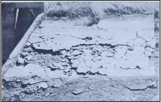
An example of damage caused by long time action of sulfate attack on hydraulic structure is shown in Figure 12 [15]. From the United States Bureau of Reclamation literature, examples of sulfate attack in spillways are documented, such as the tests performed on concrete cores from the south spillway at Guernsey Dam (Wyoming), and Alcova Dam, Kendrick Project, (Wyoming). Both dams are located in areas which are now known to have potential for high concentrations of sulfates and were built before the first sulfate resisting cements were used by the Bureau [16].
Figure 12: Disintegration of concrete caused by sulfate attack.
After first reporting of sulfate attacks on concrete, the phenomenon has been widely-studied and well-documented as a type of degradation in hydraulic structures.
As already been explained; sulfate ions dissolved in water in contact with the structure provokes the so-called (ESA) and sulfates ions present in the concrete itself is called (ISA). The internal presence of sulfates can occur when the concrete has an excess gypsum used as setting retardant in the cement hydration process or, in the concrete aggregates used which contain gypsum, iron sulfides or other salts together with the sulfates. One example of Sulfate Attack is the case of Mequinenza dam (Spain), explained in the following paragraph.
5.1 The Mequinenza Dam Study Case
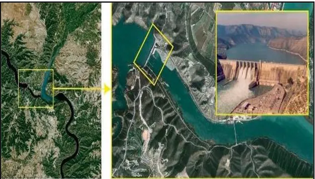
The dam at Mequinenza is a gravity dam located in the province of Zaragoza (Spain), and is located on the Ebro River. The maximum dam height is 79m and its crest length is 461m. The total dam body volume is (1.1×10⁶m3). The reservoir was first filled in December 1965, although its level was later lowered and filled again in 1969, refer to Figure 13.
The Mequinenza dam was built upon materials in which chemical sediments (limestone and gypsum) are predominant over detrital ones.
Figure 13: Left: Location of Mequinenza dam. Right: Downstream face of the dam.
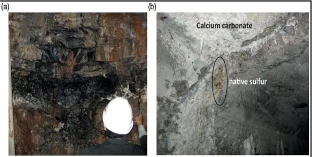
As it happens in most of the Ebro Basin (except the strips near the ranges that surround it), the strata from the Tertiary period remain practically horizontal, just as they were deposited. The aforementioned carbonate domains of these units include coal lignite layers in the Mequinenza mining district. These are groups of small layers with thickness of 20–80cm characterized by their sub horizontal position and great continuity. The lignites at Mequinenza are high-sulfur content coals. Some reports reported an average sulfur content of 13.35% (expressed as total sulfur), similar to the 13.6% found in another source. Other source claims dry-sample sulfur contents for lignites ranging from 7.6% to 11.4%. Sulfate attack problems appeared on various degraded parts of the dam. Efflorescence samples were collected, and concrete core were extracted from all concrete blocks and auxiliary elements of the dam especially the most degraded galleries. These galleries are Gallery 22m and Gallery 81m located in an area of the abutments in contact with the terrain where lignites exists, refer to Figure 14.
Aggregates from the gravel and from the surroundings of the dam and lignites from the old mine were also collected. Examination of aggregates from the dam concretes revealed that it was composed of rounded gravel, this gravel was extracted from the surrounding area, in this case the Lower Pleistocene terraces. The dam was completed in 1964 and there is no precise reference to the type of cement used in the concretein construction. No mention is made in the Dam Book of the concrete additives that could have been used. The concrete core samples were stained, and tests showed neither sulfates nor gypsum have been found, together with the limestone nature of aggregates, which rules out the possibility of an internal sulfate attack in concrete. Most of the concrete core samples did not show signs of degradation owing to Alkali Aggregate Reaction except some rims in aggregates and white gel, both typical signs of an Alkali Aggregate Reaction. Few samples analyzed by means of SEM-EDX showed AAR gel as well as secondary Ettringite filling the concrete pores.
Figure 14: a) Lignite horizons in rock present in the abutment at gallery 22 m level. b) Part of wall and ceiling of gallery 22.
However, these degradation products are not fully extended in the concrete matrix and are located in a few pores. But, Thaumasite Sulfate Attack (TSA) was evident in gallery 81m indicating signs of a severe concrete degradation in the chutes through which the filtered water flows in the gallery and, to a lesser extent, in the walls, refer to Figure 15. Thaumasite is a silicate mineral with chemical formula Ca3Si(OH)6(CO3)(SO4)·12H2O.
Figure 15: a) Brownish waters in the floor of gallery 81m. b) and c) Photos of the wall and chute where water is flowing in gallery 81 m.
Thaumasite sulfate attack (TSA) is a special form of sulfate attack typically occurring due to the availability of carbonates in the cementitious matrix with abundance of moisture and a prevailing low temperature. It transforms concrete into a non-cohesive mass without any binding or load carrying capacity.
The sulfate concentration in water, analyzed by atomic absorption, was 1528ppm. More specifically, at least the 5 first centimeters of concrete in the chute crumbles in the hand. In this zone samples were extracted every 2 meters and the analysis of concrete shows that degradation was caused by a sulfate attack in which thaumasite has formed.
Expansive reactions in the concrete of certain parts located near the abutments of the two galleries have been observed as a consequence of an external sulfate attack due to the sulfur compounds contained in the lignites that are present on the surrounding terrain. The Mequinenza dam concretes are made with rolling aggregates which mostly have a carbonate nature. No iron sulfides or other sulfur compounds appeared in those materials, which is one reason why an internal sulfate attack (ISA) can be ruled out.
Some other authors have already explained that the highest degradation of concrete occurs in areas which have been in permanent contact with water, more specifically in the chutes that act as drains in one of the galleries and in the walls where water
seepage appear. A large part of the concrete in those chutes has become mass without any cohesion during a sulfate attack process leading to (TSA) formation in a case of External Sulfate Attack [17].
Further reading on sulfate reaction impact on concrete dams can be made by referring to the case of Lijiaxia Concrete Dam Gallery (China) [18]. One more paper can be also referred to on three Spanish dams plagued by sulfate reactions, namely; Torán, Graus and Tavascán dams and under the title “Evaluation of the behavior of concrete gravity dams suffering from internal sulfate attack” [19].
6. Concrete Deterioration Mechanisms Caused by Physical
Agents
These mechanisms may be differentiated in those caused by temperature variations, settlement, sediments and debris, earthquake vibration, and high velocity flow and appear in one of the following forms.
6.1 Abrasion of Concrete
Concrete Dams and concrete ancillary works in earth fill dams are subject to damage due to physical forces acting on the dam. One of these physical factors causing wear and tear to concrete surfaces in the waterways is abrasion. Abrasion results from both concrete with low strength and poor aggregates, and by design related problems, so that rocks and sediments carried by the strong water current to the downstream are sweep back into spillway and outlet works stilling basins resulting in particles abrading the surface in a roller-mill fashion. The hydraulic jump sections of those stilling basins where turbulent flow conditions occur, are particularly vulnerable to abrasion damage. Even the best concrete cannot withstand this wearing action for very long time and such damage results in disintegration of the material exposed to the abrasion mechanism. Erosion damage can be very severe but generally would not cause total failure. It may, however, impair the function of the structure and require intensive costly repair works, while such repair works interrupt its operation causing additional economic losses. Figure 16 shows the abrasion erosion damage that occurred to the dentate, walls, and floor areas of the Yellowtail Afterbay Dam in USA sluiceway stilling basin. Characteristic of this type of erosion is the badly worn reinforcing steel and aggregate as shown in the same figure.
Figure 16: Abrasion erosion on concrete in the dentates, walls, and floors of the Yellotall Afterbay Dam Sluiceway stilling basin. The “ball mill” action of
cobbles, gravels, and sand in turbulent water abraded the concrete, thus destroying the integrity of the structure.
Although most severe cases of abrasion damage occur in the areas just described, similar damage could be expected in diversion tunnels, canals, and pipelines
carrying wastewater. Use of concrete of increased strength and wear resistance offers some relief against
the forces of erosion brought about by movement of abrasive material, abrasion and impact of traffic, sandblasting, and floating ice [20].
If major repair or rehabilitation is required, the state of the structure must be studied carefully and compared to the original conditions. The final outcome will determine the best method and repair materials which are going to be used. One example of such work was the repair of abrasion erosion damage to a spillway water diversion structure shown in Figure 17. In this case, it was ascertained after surveying the extent of damage, that the cause of this damage was abrasion erosion. After cleaning, it became apparent that the defective parts were much more widespread and serious than originally thought as seen in Figure 18. In this particular case, concrete was easily removed to significant depth over most of the spillway. Thorough investigation was conducted by obtaining and examining concrete cores from several defective parts. It was only possible then to determine the best treatment needed [21].
Figure 17: Abrasion erosion damage to the flip bucket and energy dissipators. The cause of the damage was not determined prior to starting
repairs
.
Figure 18: After beginning of concrete removal, the extent of damage became clear. Concrete was easily removed due to extensive deterioration.
One case study of similar damage is illustrated in Figure (19a) of another spillway chute damaged by abrasion. The damage was clearly visible on the surface of the spillway slab, side walls, pillars of the gates and the energy dissipation blocks. These parts were found damaged at several points which had been caused by abrasive processes. The location of the damaged part on the wall is indicated by the red circle as highlighted in Figure (19a). Similar defects on the spillway slab are shown in Figure (19b).
Figure19: (a) Dam Spillway deterioration by abrasion. (b) Defect in the concrete structure caused by abrasive process.
Many alternative materials for repairing these defects could be suggested including, mortar with silica fume with optimum content of about 10% of cement mass replacing the fine aggregate, epoxy mortar, polymer mortar, concrete with steel fiber or high strength concrete with characteristics similar to concrete used in dam construction in a mix of 1:1.61:2.99:0.376 (cement:sand:gravel:water) with cement content of 426 kg/m3 [22]. In another case study cited by the same reference, the repair of spillway chute of hydroelectric plant located in southern Brazil was done by adding polymeric materials to the concrete used to repair hydraulic surface degrades and damaged parts of the abrasive processes. The materials used was mixture of agglutinated low-density polyethylene (LDPE), crushed polyethylene terephthalate (PET) and rubber from useless tires. An overview of the dam spillway is shown in Figure (20a) Details of displacements in the surface caused by hydraulic abrasive processes are shown in Figure (20b).
Figure 20: (a) Overview of the spillway of the dam. (b) Detail of the displacement of the surface caused by hydraulic abrasive
processes.
After long service of old dams where roughened concrete surfaces have been developed already, the impact of abrasion erosion damage will be intensified and can be quite severe in large old dams and in the rivers of heavy loads of sediments.
6.2 Cavitation of Concrete
Cavitation occurs in concrete surfaces in spillway chutes, tunnels and stilling basins in dams and other hydraulic structures when their surfaces are subject to very high velocity flow. It is one of the most destructive mechanisms in such structures if it is allowed to start. Moreover, it is one to which concrete or any other construction material offers very little resistance regardless of its quality.
Cavitation is aggravated by aggregate pop outs, construction related offsets, and deposits of carbonates leaching product from concrete. Cavitation is triggered when high velocity flow is obstructed or met with abrupt change of surface alinement or surface roughness such as might occur on concrete surfaces misalignments because of poor formwork or inferior finishing of the concrete or due to deterioration of the concrete surface as the case may develop in older dams after long service in passing high floods.
The mechanism of cavitation develops when sub-atmospheric pressure zones of small fast bubbles are formed in contact with concrete or metal surface as very high velocity flow passes over them while the temperature remains constant. The bubbles instantaneous collapse results in concentrating tremendous amount of energy. The impact of the collapse has been estimated in some cases to produce pressures as high as 100,000 pounds per square inch. Repetition of these high energy blows eventually forms the pits or holes known as cavitation erosion. On spillways chutes
and bottom outlets, cavitation may occur at clear water velocities of between 12 to 15m/s which may result in severe damage and can reach dangerous limits especially when velocities exceed 25m/s. Therefore, protection is needed at these velocities. Cavitation can be prevented by decreasing the flow velocity or by increasing the boundary pressure.
With velocities greater than 20 to 30m/s, the tolerances of surface finish required to avoid cavitation are too severe and the cost of cavitation resistant materials is prohibitive. For these reasons, it becomes usual to protect the spillway surface from cavitation erosion by introducing air next to the spillway surface using aeration devices located on the spillway bottom and sometimes on the walls [23]. Such aerators were added as a remedial measure to stop cavitation in the Glen Canyon tunnel spillways as will be described hereunder as a study case. In recent developments stepped spillway chutes are designed to increase turbulence in the flow and prevent sub- atmospheric pressures formation. Cavitation may occur on horizontal or sloping surfaces over which water flows or on vertical surfaces past which water flows. Figure 21 is an illustration of cavitation erosion on surfaces of adjacent stilling basin dentates [20].
Figure 21: Cavitation erosion of concrete on a dentate in the Yellowtail Afterbay Dam spillway stilling basin. Fast-moving water during aflood flow,
caused a pressure phenomenon at the concrete surface which triggered cavitation damage shown here
.
Examples of major spillway damage by cavitation include Hoover Dam (USA), Aldea-Davilla Dam (Portugal), Yellowtail Dam (USA), Tarbela Dam (Pakistan), Karun Dam (Iran), Glen Canyon Dam (USA). In most cases, spillway aeration devices were installed as part of the remedial measures.
6.3 Glen Canyon Dam Case
Dramatic cavitation and subsequent erosion of the two emergency spillways at Glen Canyon Dam in 1983-84 required reconstruction of the spillways and installation of “air slots” to aerate the spillway flows. Glen Canyon Dam is a concrete arch-gravity dam on the Colorado River in Northern Arizona, United States. The 216m high dam was built by the U.S. Bureau of Reclamation from 1956 to 1966 and forms one of the largest man-made reservoirs in the U.S. with a capacity of 3.3 x 10⁹m3. A 950MW power plant is located at the toe of the dam. An outlet, with four hollow jet valves, having a total capacity of 425m3/s is located on the left abutment, refer to Figure 22.
Figure 22: Downstream view of Glen Canyon Dam showing the Power Station and outlets of the two tunnel spillways
.
The dam has two open-channel flow tunnel spillways, one on each abutment with the shape as shown in Figure 23. Each spillway is 12.5m in diameter and has a maximum capacity of 2900m3/s. Flow of each spillway is controlled by radial gates
which then passes into a 55º tunnel, a vertical bend (elbow), and 305m of horizontal tunnel to a flip bucket. Both spillways were operated for extended periods in 1980.
Figure 23: Glen Canyon, tunnel Spillways-aerator slots. (Upper Right-hand Corner
).
In 1981, an inspection revealed that deposits from cracks in the lining had initiated cavitation damage at several locations in the left spillway. Little damage had occurred in the right hand side spillway which was probably due to the shorter operating time. Following this inspection, surveys and studies were performed to document the damage and to identify the scope of work required for repair and to prevent future occurrence. It was recommended the damage be repaired and aerators be installed near station 6+86.0. These modifications were planned to begin in 1984, but high flows in the Colorado River occurring in the spring of 1983 had to be passed through the spillway.
At the end of the flood, extensive damage had taken place in both tunnels as shown in Figure 24. Even though damage was extensive, it only excavated a hole of a depth of about 11 meters. At this point, the eroded cavity was evidently large enough to dissipate the energy of the high velocity water.
In the elbow portion of the tunnels, the depth of the damage as noted in Figure 25 was on the same order as the depth of the flow.
Figure 24: Glen Canyon Left Spillway Tunnel, September 1983. The "big hole" in the spillway invert was 11 meters deep.
The decision taken for repair was to construct aerators to inject air in the inclined portions of the spillways to stop future cavitation damage. After thorough study and modelling and design work, the aerators consisted of a ramp, a groove or slot, a downstream offset, and a transition back to the original tunnel diameter as shown on the earlier Figure 23 upper right corner. The ramp is 1295mm long and 180mm high at the centerline of the invert. The ramp feathers out to zero height at the springline. The groove is 1200 x 1200mm. The downstream edge of the slot is offset 305mm from the original tunnel diameter. The length of the transition to the original tunnel diameter is 6.1m. The end of the ramp is at station 6+86.5 which is 96.2m below the maximum reservoir elevation. The tunnels were ready for service after finishing construction on 10 October 1984.
Figure 25: Glen Canyon Dam, tunnel Spillways- damage profiles.
In August 1984, the left tunnel was tested to verify the operation of the aerator. Pressure measurements were taken in the invert to compare with model studies and air velocities were measured in the air groove to estimate the airflow quantity. Flow rates up to 1416 cubic meter per second were passed through the spillway. This discharge was 40% greater than had previously passed through the spillways. In addition, a discharge of 566 cubic meter per second was maintained for 48 hours. This flow rate and duration had caused damage to the spillway during the 1980-81 flows. Evidence of large damage could not be found following the tests even though some eroded areas, at the end of the elbow, had been left unrepaired.
At Glen Canyon Dam, in the section downstream of the elbow, only damaged sections deeper than 19mm were repaired. Depending upon the extent of the damage one of two methods of repair was used. For small areas, the damaged surface was
ground to a 1:20 (vertical to horizontal) slope in the direction of flow and to a 1:5 slope perpendicular to the direction of flow. For large damaged areas, the concrete was removed down to the first mat of reinforcing steel and then replaced with a concrete patch. Bolts and expansion anchors, which could not be removed, were cut off above the surface and ground down to be flush with the surface. Cutting off the bolts below the surface and plugging the hole, with hydrated cement or “Burk Water Plug” compound, was limited to bolts or anchors in which the concrete around them had spalled [24], [25].
A similar cavitation problem in a very large dam had set the precedence of damage caused by cavitation before the Glen Canyon Dam case; this was the case of Hoover Dam.
6.4 Hoover Dam (USA)
This Dam is 226.4m high concrete gravity arch dam on Colorado River which impounds Lake Mead, the largest reservoir in the United States with volume of 35.2x10⁹m3 when it is full. The hydropower station of this dam had undergone upgrading from 1986 to 1993, making the total gross power rating for the plant 2080 megawatts. The average power generated was 4.2TWh/year for the period 1947-2008. In 2015, the dam generated 3.6TW/h. Plan view of the dam is shown in Figure 26; it illustrates the details of the dam and the appurtenant structures including the two gated spillways intakes, followed by the spillways tunnels; one on Arizona side and the other on Nevada side of the river. Construction of the dam and appurtenances was completed in 1936, but the two spillways (the Arizona and the Nevada tunnel spillways) were not used until 1941. At that time, a relatively small average discharge of about 384 cubic meter per second was passed through each of the tunnels for about four months.
Figure 26: Hoover Dam Plan and Appurtenant Structures.
During testing of the two spillways in 1941, the drum gates were raised, and the reservoir continued to fill reaching level 1220.45 feet by July 30; within 11.55 feet of the dam crest. On the 6th August, the drum gates were gradually lowered and several months of spillways testing ensued, which continued through early October. View of water discharging from lake Mead over the four drum gates of the Nevada spillway during the spillway tests is given in Figure 27.
Figure 27: Water from Lake Mead discharging over the four drum gates of the Nevada spillway during spillway tests in August and October 1941.
Relatively modest flows, never exceeding 368 cubic meter per second were passed through both spillways for four months. Even with these modest flows, velocities at the elbows reached 175fps (53.3m/s) and cavitation damage ensued on both spillways. The cavitation was most severe on the Arizona spillway elbow, where a hole 112ft long, 35ft wide, and up to 36ft deep was eroded into the high strength reinforced concrete on this spillway; this is illustrated in Figure 28 [26].
The original volume of the cavity was 1069.6 cubic yards (818m3). Repair work was started almost immediately, but because it was believed that ordinary concrete was not suitable it was decided to utilize the (Prepack and Intrusion) process of concrete repair developed by Durite of Chicago. After repair, the tunnel was polished smooth to help prevent any future erosion [27].
Figure 28: Cavitation damage observed in December 1941 in the elbow of the Arizona spillway after modest discharges passed through the spillway
between August and October 1941.
It was judge that the most probable reason of this damage was being an abrupt misalignment in the tunnel invert that deflected the high velocity flow causing sub-atmospheric pressures and the formation of vapor pockets. Subsequent implosion of these vapor pockets further downstream caused cavitation damage which destroyed the integrity of the concrete lining and eventually led to the massive erosional damage.
Hydraulic model testing to design a good mean for injecting air into the flow as a corrective measure which followed, gave negative results, but the tunnel spillways, however, were not used again until the 1983 floods. Comparatively low flows (less than 283m3/s) through each spillway were discharged for several hundred hours. Minor cavitation damage occurred, more in the Nevada than the Arizona tunnel. Since it was known that this type of damage is cumulative, it was decided that efforts on installing new aeration devices in both tunnels should be resumed [28].
From 1941, the year of the first model testing, till 1983 more had been learned about the nature of cavitation problems which allowed designing, testing, and installing more successful aeration devices in the two tunnel spillways. The effectiveness of
aeration has been thoroughly demonstrated, however, the aeration scheme must be well designed to assure that it is effective through the entire range of operations. After the 1983 floods, reclamation undertook a comprehensive program to retrofit their high dams to alleviate cavitation, using aeration slots. These slots were added to the Hoover Dam spillways in 1985-1986 [29].
In summary, cavitation damage could occur in newly built dams, if the hydraulic conditions as described are favorable. The chances of the same phenomenon to develop in old dams are much more. In these dams cracking or displacements of concrete surfaces and misalignments which are subject to the high velocity flow, in addition to erosion by high floods, settlement cause by earthquakes are all good reasons to develop cavitation in these dams. In such cases, therefore, cavitation damage are to be looked for during routine inspections and prompt treatment are carried out, which normally are not cheap jobs.
7. Conclusion
From the proceedings it is clear that aging concrete dams present serious problems of safety hazard on downstream communities and can cause fatalities and material damage in case of failure. Major rehabilitation work in the present economic environment may require large investment in view of soaring costs. In addition to diminishing benefits and soaring costs of repair and upgrading. As conclusions from this presentation the following may be drawn.
1. Concrete dams design and construction methods have evolved over more than 120 years. At the present such dams may present safety risks by the fact that data and methods of analysis used at those days have mostly become obsolete. The decision to repair old concrete dams must be based on reviewing their general safety as to stability and integrity together with evaluating all the damages sustained during these years.
2. Aging processes of concrete dams result from both external and internal factors. These factors include temperature variations, freeze and thaw, settlement, earthquake vibration, abrasion and cavitation by high velocity flow, blocked drains, chemical reactions between concrete constituent’s material and water as in alkali aggregate reaction and sulfate attacks, and corrosion of metal parts. While some of these factors are unavoidable by their nature, the effects of others can be reduced by good design and controlled construction.
3. The aging of these dams is a reactive process between the elements of nature and the dam structure and again reactive it is reactive process between its constituents which renders these dams’ unsafe sooner or later.
4. The relatively long history of concrete dams’ construction has given lot of opportunities to encounter various types of damages. Using study cases of many of such occurrences has accumulated rich experience in the causes and effects and this allows the construction of better dams. To say that the life of any dam can be elongated indefinitely is false. It is the nature of all
man-made structures to decay with time and nothing can be man-made to stop this decay. Slowing down of this can be achieved by good design and by repairs and upgrading until such things become technically and economically not possible. After this the only alternative left is tearing down the dam and removing it.
References
[1] Jansen, R. (1983). Dams and Public Safety. USBR Water Resources Publication, pp.108-109.
https://www.usbr.gov/tsc/techreferences/mands/mands-pdfs/AZ1130.pdf
[2] USBR Projects and Facilities (2020). Clear Creek Dam. Retrieved March 12th, https://www.usbr.gov/projects/index.php?id=69
[3] Wikipedia (2020). Clear Creek Dam. Retrieved March 12th
https://de.wikipedia.org/wiki/Clear_Creek_Dam
[4] Thomas, M. D. H., Fournier, B. and Folliard, K. (2013). Alkali aggregate Reactivity-ARR Fact Book. U.S. Department of Transportation, Federal Highway Department. Report No. FHW-HIF-13-019, pp.1-5, March.
https://www.fhwa.dot.gov/pavement/concrete/asr/pubs/hif13019.pdf
[5] Dolen, T. P., Gregg, A., S., von Fay, K.F. and Hamilton, B. (2003). Effects of Concrete Deterioration on Safety of Dams, Alkali-Aggregate Reactions. Dam Safety Office Report No. DSO-03-05 Draft, p.8, Department of the Interior Bureau of Reclamation December.
https://www.usbr.gov/ssle/damsafety/TechDev/DSOTechDev/DSO-03-05.pdf
[6] USBR (2019). Maintenance and Rehabilitation of Spillway and Dam Structures at American Dam Falls. Final Report Findings, 20th May.
https://www.usbr.gov/pn/programs/ea/idaho/americanfalls/finalea.pdf [7] Douglas, R. and Hurcomb, P.G. (2014). Seminoe Dam. Assessment of
Concrete by Quantitative Methods-The Petrographic Damage Rating Index. Report DSO- USBR Safety Technology Development Program 30th June. https://www.usbr.gov/ssle/damsafety/TechDev/DSOTechDev/DSO-14-03.pdf
[8] Dallman, J. (2016). Seminoe Concrete Repair. USBR, News & Multimedia Published on May 30, retrieved on 29th Feb 2020.
https://www.usbr.gov/newsroom/stories/detail.cfm?RecordID=56838
[9] Saouma, V., Hariri, M. H. A. and Al-Saffar, A. (2019). Long Term Assessment of Dams Suffering from Alkali Aggregate Reaction. Dept. of Civil Engineering, University of Colorado, Boulder May.
https://ceae.colorado.edu/~saouma/wp-content/uploads/2019/06/Reclamation-May-2019_Redacted-1.pdf [10] Scuero, A. M. and Vaschetti, G. L. (2004). Watertightness and Safety of Dams
Using Geomembranes. Long-Term Benefits and Performance of Dams.
Thomas Telford, London. https://britishdams.org/2004conf/papers/scuero.pdf [11] Benoit, F. and Bérubé, M. (2014). Alkali-Aggregate Reaction In Concrete: A
Review Of Basic Concepts and Engineering Implications. Canadian Journal of Civil Engineering, February 2011, uploaded on the internet in August.
https://www.researchgate.net/publication/237191439_Fournier B. (2010).
Alkali-aggregate Reactions in Concrete – A review. CEA conference. http://www.ibracon.org.br/eventos/52cbc/Fournier.pdf
[12] Farny, J. A. and Kerkhoff, B. (2007). Diagnosis and Control of Alkali-Aggregate Reactions in Concrete. Portland Cement Association.
https://www.cement.org/docs/default-source/fc_concrete_technology/is413-02---diagnosis-and-control-of-alkali-aggregate-reactions-in-concrete.pdf [13] Dolen, T. P. (2001). Historical Development of Durable Concrete for the
Bureau of Reclamation. Materials Engineering and Research Laboratory Technical Service Center – Denver, Colorado.
http://www.riversimulator.org/Resources/USBR/ReclamationHistory/DolenT imothyP.pdf
[14] U.S. Bureau of Reclamation (1975). Concrete and Concrete Materials- Disability, pp. 7-12, Concrete Manual 8th Edition.
https://ia803107.us.archive.org/0/items/concretemanualma00unit/concretema nualma00unit_jpg.pdf
[15] Dolen, T. P., Gregg, A. S., Von Fay, K.F. and Hamilton, B. (2003). Effects of Concrete Deterioration on Safety of Dams- Sulfate Attack. Dam Safety Office Report No. DSO-03-05 Draft, P 8, Department of the Interior Bureau of Reclamation December.
https://www.usbr.gov/ssle/damsafety/TechDev/DSOTechDev/DSO-03-05.pdf
[16] Chinchón-Payáa, S., Aguadob, A., Nugterenc, H. W. and Chinchóna, S. (2015). External sulfate attack in dam concretes with thaumasite formation. Materiales de Construcción, Vol. 65, Issue 317, January–March 2015. Received 4 December 2013, Accepted 22 May 2014. Available on line 26 January 2015 http://materconstrucc.revistas.csic.es/index.php/materconstrucc/article/viewFi le/1679/2038.
[17] Zhu, X., Li, J., Zhang, Y., Song, H. and Zheng, H. (2017). The Sulphate Effect on Lijiaxia Concrete Dam (China) Gallery. Hidawi Journal of Chemistry, Volume 2017, p.8, published 3 October.
https://www.hindawi.com/journals/jchem/2017/8698759/ [18] Araújo, G. S., Chinchón, S., and Aguado, A. (2008). Evaluation of the behavior
of concrete gravity dams suffering from internal sulfate attack. IBRACON, Structures and Material Journal, Volume 1, Number 1, pp.12-15.
http://www.scielo.br/pdf/riem/v1n1/en_05.pdf
[19] U.S. Bureau of Reclamation (1975). Concrete Manual. A Water Resources Technical Publication, Eighth Edition.
https://usbr.gov/tsc/techreferences/mands/mands-pdfs/ConcreteMan-8th_Ed-rev.pdf
[20] Fay, V. K. F. (2015). Guide to Concrete Repair. US Bureau of Reclamation. Second Edition, August.
https://usbr.gov/tsc/techreferences/mands/mands-pdfs/Guide2ConcreteRepair2015_Final.pdf
[21] Galvão, J. C. A., Portella, K. F. and Kormann, A. C. M. (2012). Abrasive Effects Observed in Concrete Hydraulic Surfaces of Dams and Application of Repair Materials. Federal Technological University of Paraná, Institute of Technology for Development, Federal University of Paraná, Brazil, March. https://cdn.intechopen.com/pdfs/31698/InTech-Abrasive_effects_observed_in_concrete_hydraulic_surfaces_of_dams_and_a pplication_of_repair_materials.pdf or https://www.intechopen.com/books/abrasion-resistance-of- materials/abrasive-effects-observed-in-concrete-hydraulic-surfaces-of-dams-and-application-of-repair-materials
[22] Chanson, H. (2020). Design of Spillway Aeration Devices to Prevent Cavitation Damage on Chutes and Spillways. The University of Queensland, School of Civil Engineering., Brisbane QLD 4072, Australia. Blog page retrieved on 6th March. http://staff.civil.uq.edu.au/h.chanson/aer_dev.html [23] Falvey, H. (1990). Cavitation in Chutes and Spillways. US Bureau of
reclamation. Water Resources Technical Publication, Engineering Nomograph No.42, pp. 81-83, April.
https://www.usbr.gov/tsc/techreferences/hydraulics_lab/pubs/EM/EM42.pdf [24] Wikipedia (2020). Risks to the Glen Canyon Dam. Retrieved on 6th March.
https://en.wikipedia.org/wiki/Risks_to_the_Glen_Canyon_Dam#Tunnel_spill ways_damaged
[25] Rogers, D. (2010). Hoover Dam: Operational Milestones, Lessons Learned, and Strategic Import. Hoover Dam 75th Anniversary History Symposium Oct. p.21-22, Las Vegas, NV.
https://web.mst.edu/~rogersda/hoover_dam/Rogers-HooverDam-Pt4.pdf [26] U.S. Bureau of Reclamation (2020). Hoover Dam Spillway/ Essays-Spillways.
Last Updated: 3/12/15. Retrieved on 3/7/2020.
https://www.usbr.gov/lc/hooverdam/history/essays/spillways.html
[27] Houston, K.H., Quint, R.J., Rhone, T.J. (1987). Hoover Dam Tunnel Spillway Damage. PAP 494 U.S. Bureau of Reclamation May.
https://www.usbr.gov/tsc/techreferences/hydraulics_lab/pubs/PAP/PAP-0494.pdf
[28] Pugh, C. A. and Rhone, T. J. (1998). Cavitation in Bureau of Reclamation Tunnel Spillways. PAP 526 US. Bureau of Reclamation, The International Symposium on Hydraulics for High Dams. Beijing.
https://www.usbr.gov/tsc/techreferences/hydraulics_lab/pubs/PAP/PAP-0526.pdf