http://www.diva-portal.org
Postprint
This is the accepted version of a paper presented at PowerTech Eindhoven 2015.
Citation for the original published paper:
Adib Murad, A., Gómez, F J., Vanfretti, L. (2015)
Equation-Based Modeling of Three-Winding and Regulating Transformers using Modelica.
In: IEEE conference proceedings
http://dx.doi.org/10.1109/PTC.2015.7232503
N.B. When citing this work, cite the original published paper.
Permanent link to this version:
Equation-Based Modeling of Three-Winding and
Regulating Transformers using Modelica
Mohammed Ahsan Adib Murad, Francisco José Gómez
KTH, Royal Institute of Technology,Stockholm, Sweden
maamurad@kth.se , fragom@kth.se , luigiv@kth.se
Luigi Vanfretti
KTH Royal Institute of Technology, Stockholm, Sweden Statnett SF, Oslo, Norway
luigi.vanfretti@kth.se, luigi.vanfretti@statnett.no
Abstract—The simulation of power transformer models is a
critical for analyzing the dynamic behavior of power systems, in particular, when considering voltage magnitude or phase regulation controls. This paper reports results of extending the library of transformers in the iTesla Modelica Power Systems Library. Three transformer models have been implemented: a three-winding transformer, an under-load tap changing transformer (ULTC) and a phase shifting transformer (PST). A simple power system test model was also implemented, both in Modelica and PSAT, to assess the performance of the models. Software-to-software validation is carried out against PSAT.
Index terms – Modelica, PSAT, Power Transformer, Simulation
Software, Power System Simulation.
I. EXTENDED ABSTRACT
Adequate modeling of conventional and controllable power transformers allows studying the dynamic behavior of power network under certain different operating conditions. In the literature, classical transformer models are studied [1]. Different transformer models have been developed, each focusing on a particular application or to represent specific physical phenomena. Generally, transformer models are classified according to their application: lightning overvoltage studies or the purpose of elements of the model, e.g., models based on leakage inductance, transmission line modeling, etc.
From the models above, those used in phasor time-domain simulations can be easily implemented using equation-based modeling languages. This kind of languages allows engineers to implement models directly using mathematical equations. The Modelica equation-based modeling language is object-oriented and open-source, which allows model implementation directly from mathematical equations. This is an important characteristic, which implicitly decouples the model from the mathematical solver, thus providing unambiguous simulation results among different tools [2]. The attractive features of this language have been successfully applied in different areas such as the automotive and aerospace industry [3].
European transmission system security is becoming a challenge due to the growing complexities of the pan-European power network. To overcome these complexities, the FP7 iTESLA (Innovative Tools for Electrical System Security within Large Areas) project was initiated to develop a toolbox that will support the operation of the European transmission network [4]. The iTesla project has adopted the Modelica language for modeling of power system dynamic components, and a Modelica library compatible with Modelica tools has been developed.
The purpose of this work is to improve this Power System Library with the implementation of new Modelica models of conventional power system components (Transformers) for Phasor Time-Domain Simulation. To implement these models the PSAT implementation is taken as reference [5]. Finally, to prove that Modelica models of transformers have the expected behavior, a software-to-software validation is performed, taken PSAT as a software reference for this validation.
II. IMPLEMENTATION OF TRANSFORMER MODELS
This work reports the implementation and validation of Modelica models for two regulating transformers and a Three Winding Transformer. The regulating transformers considered herein are: Under Load Tap Changing (ULTC) and Phase Shifting Transformer (PST) transformers. The mathematical description in [5] is taken as reference for model implementation. Due to space limitations, only one model and a summary of the rest of the work are provided in this abstract. K H+s max m min m + ref v m dead zone LTC & Network m v m
A. ULTC (Under Load Tap Changer)
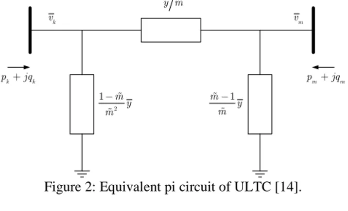
ULTC is a regulating transformer that regulates the voltage or reactive power at the secondary side of the transformer. The regulator used to control the secondary voltage shown in Fig.1. The ULTC transformer is modeled as an equivalent PI circuit as depicted in Fig. 2.
k v vm y m k k p +jq pm+jqm 2 1 m y m - 1 m y m -
Figure 2: Equivalent pi circuit of ULTC [14].
The current injection at Bus k (ik) and Bus m (im) are
calculated from:
̅
̅ 1 ̅ (1) ̅ where, is the series admittance, m is the off nominal tap ratio. The tap ratio m is the output of the regulator shown in Fig. 1. The tap ratio step ∆m is taken as zero, from where
(2) To model the secondary voltage control the differential equation used (calculated from the controller shown in Fig. 1):
(3)
B. ULTC in Modelica
The Modelica implementation of the ULTC uses the connector class PwPin [6].First the parameters are defined, as follows:
parameter Real SystemBase=100; parameter Real Vbus1=400000
"Sending end Bus nominal voltage, change of base"; parameter Real Vbus2=100000
"Receiving end Bus voltage, change of base"; parameter Real Sn=100 "Power rating MVA"; parameter Real Vn=400000
"Voltage rating, primary side KV";
parameter Real fn=50 "Frequency rating Hz"; parameter Real kT=4
"Nominal Tap ratio (V1/V2), kV/kV";
parameter Real H=0.001 "Integral deviation, p.u."; parameter Real K= 0.10 "Inverse time constant, 1/s” parameter Real m_max=0.98
"Max tap ratio, p.u./p.u."; parameter Real m_min=0.9785
"Min tap ratio, p.u./p.u.";
parameter Real deltam=0 "Tap ratio step, p.u./p.u." parameter Real v_ref=1.0 "Reference voltage, p.u."; parameter Real xT= 0.001
"Transformer Reactance, p.u.";
parameter Real rT=0.1 "Transformer Resistance, p.u. parameter Real d= 0.05 "Dead zone percentage, %";
parameter Real vm0=1.008959700699460
"Init. value of the voltage of the Controlled Bus"; parameter Real m0=0.98;
Real m "Tap ratio";
Real vk "Voltage at primary, p.u.";
Real vm "Voltage at secondary p.u.";
Real anglevk "Angle at primary";
Real anglevm "Angle at secondary ";
The parameters used to change the basis are declared as protected variables:
protected
parameter Real V2= Vn/kT "Secondary voltage"; parameter Real Vb2new=Vbus1*Vbus1;
parameter Real Vb2old=Vn*Vn;
parameter Real R=rT*(Vb2old*SystemBase)/(Vb2new*Sn)
"Transformer Resistance, p.u.";
parameter Real X=xT*(Vb2old*SystemBase)/(Vb2new*Sn)
"Transformer Reactance, p.u."; parameter Real vref=v_ref*(V2/Vbus2);
parameter Real gt= R/(R^2+X^2) "Converting resistan ce to conductance p.u.";
parameter Real bt= (X/(R^2+X^2)) "Converting reacta nce to susceptance p.u.";
Then, equations (1) and (3) are added to complete the model: equation
R*p.ir-X*p.ii= (1/m^2)*p.vr- (1/m)*n.vr; R*p.ii+X*p.ir= (1/m^2)*p.vi- (1/m)*n.vi; R*n.ir-X*n.ii= n.vr- (1/m)*p.vr;
X*n.ir+R*n.ii= n.vi- (1/m)*p.vi;
der (m)= -(H*m)+K*(vm-vref);
III. VALIDATION OF THE ULTCMODEL
Having the Modelica implementation of the ULTC, a small test power system was implemented both in Modelica and PSAT to perform software-to-software validation.
A. Test System
Fig. 3 shows the Modelica implementation of a three bus test power system. The same test system was implemented in PSAT. Initial guess values for algebraic and state variables in the Modelica test system were taken from the power flow solution calculated in PSAT.
Figure 3: Test system in Modelica to validate ULTC.
B. Validation Case: Perturbations
To test the dynamic behavior of the ULTC, perturbations are applied introduced in the test system. The perturbations are applied in such a way that the limiters of the ULTC controller are reached. The perturbations applied in this test system are: Synchronous Machine: Sinusoidal oscillation . 001 ∗ sin 2 ∗ 0.2 ∗ in the field voltage (vf) of the generator from time 0s
PQ Load: +.05 per unit (pu) reactive power load is added, from 5s to 8s, and -.05 (pu) reactive power load is added from 8s to 12s.
C. Simulation and Results
Simulations were performed both with Modelica and PSAT. The outputs of both the software tools match with negligible variation (see Fig. 4).
Figure 4: Software-to-Software validation results
REFERENCES
[1]. C. González. “Power transformer modeling analysis and survey by means of the frequency response”. Master Thesis Dissertation. Carlos III de Madrid University, september 2009.
[2]. Vanfretti, L.; Li, W.; Bogodorova, T.; Panciatici, P., "Unambiguous power system dynamic modeling and simulation using modelica tools,"Power and Energy Society General Meeting (PES), 2013 IEEE, vol., no., pp.1,5, 21-25 July 2013.
[3]. P. Fritzson, Introduction to Modeling and Simulation of Technical and Physical Systems with Modelica. Wiley-IEEE Press, 2011. ISBN: 978-1-118-01068-6.
[4]. iTesla: Innovative Tools for Electrical System Security within Large Areas. [Online]. Available: http://www.itesla-project.eu/
[5]. F. Milano, Power System Analysis Toolbox Documentation for PSAT. version 2.1.8, 2013.
[6]. D 5.2: Proof of concept for an open simulation and model sharing framework validated on a medium size power system. [Online]: http://fp7-pegase.com/ 0 2 4 6 8 10 12 14 16 18 20 -0.03 -0.025 -0.02 -0.015 -0.01 -0.005 0 0.005 0.01 Time(s) Modelica PSAT 0 2 4 6 8 10 12 14 16 18 20 1 1 1 1 1 1 1 Time(s) Modelica PSAT 0 2 4 6 8 10 12 14 16 18 20 0.995 0.996 0.997 0.998 0.999 1 1.001 1.002 1.003 1.004 1.005 Time(s) V_B u s 1 Modelica PSAT 0 2 4 6 8 10 12 14 16 18 20 0.9784 0.9786 0.9788 0.979 0.9792 0.9794 0.9796 0.9798 0.98 0.9802 0.9804 Time(s) m Modelica PSAT
![Figure 1: Secondary voltage control scheme of ULTC [14].](https://thumb-eu.123doks.com/thumbv2/5dokorg/4595118.118145/2.892.458.820.865.953/figure-secondary-voltage-control-scheme-ultc.webp)