Standardization
and modularization
of Handling system
PAPER WITHIN Product Development and Materials Engineering AUTHOR: Giulia Corti
TUTOR: Morteza Poorkiany JÖNKÖPING June 2019
Optimization of choice of roller conveyors and
loading / unloading tables for beam handling
This exam work has been carried out at the School of Engineering in
Jönköping in the subject area of product development and production
optimization. The work is a part of the Master of Science programme
Product Development and Materials Engineering.
The authors take full responsibility for opinions, conclusions and findings
presented.
Examiner: Fredrik Elgh
Supervisor: Morteza Poorkiany
Scope: 30 credits
Throughout this research project I have received a great deal of support and assistance. I would first like to thank my supervisor from Jönköping University, Professor Morteza Poorkiany, whose invaluable suggestions and expertise guided me in the formulation and explanation of the projects and its findings.
I would like to acknowledge my colleagues from Ficep, who supported me greatly and were always willing to help me, for their wonderful collaboration. I would particularly like to single out my supervisors Eng. S. Fongaro for the excellent cooperation and for all of the opportunities I was given to conduct my research and further my presentation at Ficep. I would also like to thank my tutors, Dott, A. Bossi and M. Falcetti, for their valuable guidance, providing me with the tools that I needed to choose the right direction and successfully complete my project.
Abstract
Abstract
This project was commissioned by Ficep S.p.a. and performed in the field of product development with the aim of developing a method for the revision of product architectures in standardized modular configurations.
The handling system for profiled beams has a generally well-established structure and technology among all main competitors in the mechanical carpentry sector, for this reason the key to success in the market is the optimization of the components to minimize redundancies and the ability to promptly satisfy the variegated customers’ demands while still keeping competitive prices.
The major problem in the layout of these systems is the absence of standard rules or mathematical models, relaying mostly on the empirical norms derived from the experience of the designer, thus generating confusion and variants’ proliferation. For this reason, a standardized and optimized model for generating appropriate configurations according to functional specifics is the final goal of this work.
To hit this target the development process has been analysed and reviewed all the way from the customer offer request to final layout definition, passing through the definition of the technical specifics, architecture of the handling system and inner structure of its components.
The final result is a configurator that, taking the technical specifications of the client as input data, dynamically calculates the structure of the handling system adjusting even the composition of the elements it is made up of and their position for the layout. As a side project the configurator was used to create a model for cost estimation of the handling system in stages prior to the CAD design of its layout.
Summary
Summary
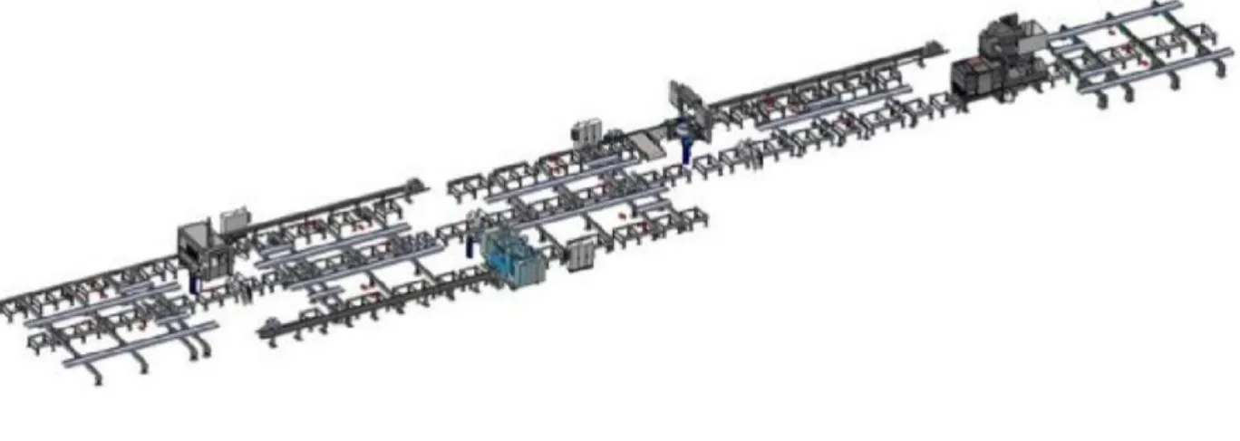
In plants for structural steel machining, the handling system has the function of moving the profiled beams throughout the whole machining cycle.
The beams enter the plants unrefined and are loaded and fed to the manufacturing machines by the handling system. The latter has also the function of moving the unfinished product between one working station and the following until the pieces have undergone all the machining to meet the customer specifications. Once again, the handling system takes care of transporting the finished beams to unloading areas to be stocked or dispatched.
Being the part of the implant that varies the most for each customer order this work was commissioned to reorganize the development process of the system with the goal of making it modular and standardize its parts and rules for configuration, generating a method equally applicable for the same process on completely different product families.
The method used to reach the goal had an inductive approach, starting from the collection of information on the market sector of the company and its competitors and data on the customer requests to be satisfied. This background information has then been analysed to formulate a method to go through all the development process of the system from the customer request to the choice and layout of the elements composing the handling system. The requests have been translated in technical specifications of the system by the historical analysis of the handling systems developed from the company for past orders and the guidance of experienced employees from both Ficep and Trennitalia. The construction of a product architecture by means of functional decomposition of the product and mapping of functions to subassemblies made it possible to recognise modules and to define a new modular product structure with standard interfaces between modules. After the definition of standard rules of configuration for the inner structure of the elements of the handling systems as well as for their assembly layout an Excel configurator has been coded to automatize the process.
The configurator is the product of the integration of all the complementary intermediate results previously mentioned and the automation potential offered by the software, which already includes built in tools for optimization and programming. As a corollary project, from the association of the configurator to the price lists of all the components of the elements of the handling system, a model for the estimation of prices has been drawn out, creating a linear function of the cost as the algebraic sum of the linearized cost functions of the components.
Summary
Keywords and Definitions
Handling system: system of automatisms that take care of feeding one or multiple
machines or of transferring the semi-finished products among the various machining centres in the plant production line.
Rollerways: elements of the handling system that convey the material along the
processing line.
Loading / Unloading Tables: elements of the handling system that handle the
material transversally with respect to the processing line.
Variety: the range of products offered by a supplier, intended as variants of the same
concept with differences to better fulfil secondary functions.
Complexity: characteristic of systems made up of a multiplicity of elements
interconnected by a high number of non-simple relationships.
Mass Customization: production and distribution of customized goods and
services on a mass scale.
Modularity: attribute of product architectures in which discrete and mutually
independent units embody a specific product function.
Standardization: approach that relies on the usage of common fixed components,
products, or processes to satisfy heterogeneous needs.
Configurator: tool for the calculation of the possible configuration solutions to the
Contents
Contents
1
Introduction ... 9
1.1 BACKGROUND ... 9 1.1.1 The company ... 9 1.1.2 The partner ... 11 1.1.3 Handling systems ... 111.1.4 State of the art ... 15
1.2 PURPOSE AND RESEARCH QUESTIONS ...16
1.2.1 Purpose ...16 1.2.2 Research questions ...16 1.3 DELIMITATIONS ... 17 1.4 OUTLINE ... 17
2
Theoretical background ... 18
2.1.1 Complexity... 18 2.1.2 Mass customization ... 20 2.1.3 Modularity ...21 2.1.4 Standardization ... 262.1.5 Previous similar studies... 29
3
Method and implementation ... 33
3.1 RESEARCH DESIGN ... 33
3.2 PRESTUDY ... 35
3.2.1 Literature research ... 35
3.2.2 Market and competitors’ analysis ... 35
3.3 DATA COLLECTION ... 37 3.3.1 Brainstorming ... 37 3.3.2 Case studies ... 38 3.3.3 Interviews ... 38 3.4 DATA ANALYSIS ... 39 3.4.1 Functional decomposition ... 39
3.4.2 Function-means tree analysis ... 40
3.4.3 Interface analysis ...41
3.4.4 Linear Optimization ...41
4
Findings and analysis... 43
Contents
4.2 TRANSLATION OF CUSTOMER REQUESTS IN TECHNICAL SPECIFICATIONS OF THE SYSTEM . 45 4.3 EFFECTS OF THE TECHNICAL SPECIFICATIONS ON THE STRUCTURE OF THE HANDLING SYSTEM
45
4.4 PRODUCT ARCHITECTURE ... 48
4.5 RULES FOR CONFIGURATION OF THE HANDLING SYSTEM AND ITS COMPONENTS ... 50
4.6 CONFIGURATOR ... 54
4.7 COST ESTIMATION ... 57
5
Discussion and conclusions ... 58
5.1 DISCUSSION OF METHOD ... 58 5.1.1 Literature research ... 58 5.1.2 Market analysis... 58 5.1.3 Brainstorming ... 58 5.1.4 Case studies ... 58 5.1.5 Interviews ... 58 5.1.6 Functional decomposition ... 58
5.1.7 Function means tree analysis ... 59
5.1.8 Interface analysis ... 59
5.1.9 Linear optimization ... 59
5.2 DISCUSSION OF FINDINGS ... 59
5.2.1 Evaluation of results ... 60
5.2.2 Research questions and answers ...61
5.3 CONCLUSIONS... 63
5.3.1 Possible future developments ... 63
Contents
Table of figures
Figure 1 - Air view of Ficep's Headquarters (Ficep S.p.A., 2018) ... 9
Figure 2 - Milestones in Ficep's History (Ficep S.p.A., 2019) ... 10
Figure 3 - Example of complete plant layout (courtesy of Ficep S.p.A.) ... 11
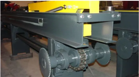
Figure 4 - Example of powered roller conveyor unit (Trennitalia s.r.l., 2019) ... 12
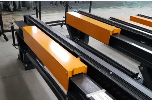
Figure 5 - Example of liftable roller conveyor (Trennitalia s.r.l., 2019) ... 12
Figure 6 - Example of loading / unloading table with catches structure (Trennitalia s.r.l., 2019) ... 13
Figure 7 - Detail view of a catch mechanism (Trennitalia s.r.l., 2019) ... 13
Figure 8 - Example of loading / unloading table with carts structure (Trennitalia s.r.l., 2019) ... 14
Figure 9 - Detail view of a cart mechanism structure (Trennitalia s.r.l., 2019) ... 14
Figure 10 - Detail view of combined cart with catch (courtesy of Trennitalia s.r.l.) ... 15
Figure 11 - Example of loading / unloading tables with combined carts with catches (courtesy of Trennitalia s.r.l.) ... 15
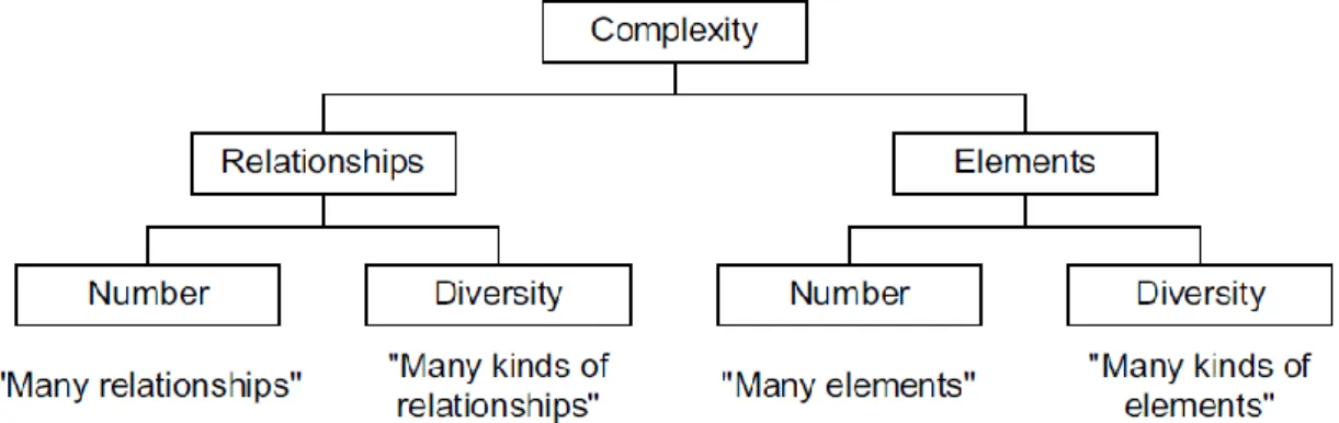
Figure 12 - Visualization of the drivers for complexity of a system (Marti, 2007) from (Patzak, 1982) ... 18
Figure 13 - Example of elements, relationships, and system structures as a measure of complexity (Marti, 2007) from (Flood & Carson, 1993) ... 19
Figure 14 - Graphical representation of trade-off between costs and benefit associated with product variety (Marti, 2007) from (Rathnow, 1993) ... 19
Figure 15 - Mass produced monogrammed shirt wherewith Davis (1987) introduced the term Mass Customization ...20
Figure 16 - Different types of building block systems (mainly according to size) (Miller & Elgård, 1998) after (Borowski, 1961) ... 22
Figure 17 - Function types and module types in modular and mixed product system (Miller & Elgård, 1998) after (Pahl, Beitz, Feldhusen, & Grote, 1996) ... 22
Figure 18 - Scheme of method for structuring the product architecture (EY, 2015) ... 23
Figure 19 - Difference between de-coupled interface and coupled interface (Ulrich, 1992) ... 24
Figure 20 - Different perception of the same object during its lifecycle (Miller & Elgård, 1998) ... 24
Figure 21 - Types of modularity (Ulrich & Tung, Fundamentals of Product Modularity, 1991) ... 25
Contents
Figure 22 - Different levels of standardization (Agard & Kusiak, 2004)... 26
Figure 24 - Dominant flow heuristic applied to a generic function structure (Stone, Wood, & Crawford, 1998) ... 29
Figure 25 - Flow branching heuristic applied to a generic function structure (Stone, Wood, & Crawford, 1998) ... 29
Figure 26 - Conversion-transmission applied to a generic set of sub-functions ... 30
Figure 27 – Example of the confusion in the choice between modules identified with the 3 heuristic approaches in the example of a SKIL Twist power screwdriver, adapted from (Stone, Wood, & Crawford, 1998) ... 30
Figure 28 - Example of binary DSM (a) and its equivalent in diagraph form (b) (Eppinger & Browning, 2012) ... 31
Figure 29 - Composite DSM including spatial, energy, information, and material interactions (left) compared to its clustered form (right) (Eppinger & Browning, 2012) ... 32
Figure 30 - Research design outline ... 33
Figure 31 - Examples of Ficep customers’ applications (courtesy of Ficep) ... 35
Figure 32 - Brainstorming session set (courtesy of Ficep S.p.a.) ... 37
Figure 33 - Principle structure of function-means tree showing alternative solutions and a candidate solution (Robotham, 2002) (Hubka & Eder, 1988) ...40
Figure 34 - Knapsack problem depiction (Terh, 2019) ... 41
Figure 35 - Brainstorming session results (courtesy of Ficep S.p.A.) ... 44
Figure 36 - First configurator interface (section) ... 46
Figure 37 - Loading / unloading tables product architecture ... 48
Figure 38 - Roller conveyors product architecture ... 49
Figure 39 - Examples of changes in handling system's configurations to varying of the working machines (courtesy of Ficep S.p.A.) ... 50
Figure 40 - Different types of liftable roller conveyors depending on the size of the saw in the plant (courtesy of Ficep S.p.A.)... 51
Figure 41 – Differences in the configuration of the handling system when short pieces have to be moved (top) compared to normal length pieces (bottom) (courtesy of Ficep S.p.A) ... 52
Figure 45 - Configurator user interface ... 54
Figure 46 - Setting of the optimization problem parameters behind the configurator's calculation ... 55
Contents
Figure 47 - Depiction of the base principle behind the choice of rollerways (courtesy of
Ficep S.p.A.) ... 56
Figure 48 - Cost trends for rollerways IN, each line corresponding to a weight class 57 Figure 49 - Area representing the delta cost function between the 1085 kg/m weight class and standard weight (485kg/m) ... 57
Figure 50 - Example of 3D line layout automatically generated using dummy models of machines ... 63
List of tables
Table 1 – Determining cost components in standardization process definition (Perera, Nagarur, & Tabucanon, 2000) ... 28Table 2 - Chart relationship representation ... 31
Table 3 - Effects of the technical specifications on the structure of the handling system ... 45
Table 4 - Loading / unloading tables rules for optionals’ configuration chart ... 53
Table 5 - Roller conveyors rules for optionals’ configuration chart ... 53
List of equations
Equation (1)...32Equation (2)...42
Equation (3)...47
Contents
1
Introduction
1.1 Background
1.1.1
The company
Ficep S.p.A. is an Italian company producing machinery and complete production systems for the processing of structural steel (beams, profiled beams, thick metal sheets, etc.) and auxiliary machines for the metal forging industry. (Ficep S.p.A., 2018) It was founded in 1930 by Colombo and Giuliani families as "Fabbrica Italiana Cesoie e Punzonatrici" (Italian Shears and Punching Machines Factory), the company has nowadays gained the leading position in the market of automated systems for the manufacturing of structural steel and forging equipment (Ficep S.p.A., 2018) (Ficep S.p.A., 2019).
Ficep’s mainstay lies in the ability of managing the whole manufacturing cycle of structural steel, offering its customers complete and fully automated solutions, specific for each order, a wide range of machine-tools that can work both sheet metals and profiled beams and the supply of turn-key plants.
The headquarters are located in Gazzada Schianno, next to the Alps, where the company has grown up to a surface of over 100˙000 square meters. Here their products are followed in all the steps from conception to realization: the implant includes the R&D department complete with laboratories, three areas of machining workshops, one assembly area, the showroom and the main after sales service departments. (Ficep S.p.A., 2018) The same industrial complex houses also the Academy of Technology, whose objective, in line with Ficep’s philosophy, is to share knowledge through training courses and technical workshops. (Ficep S.p.A., 2019)
Contents
1.1.2
The partner
Ficep does not produce the elements of the handling systems in-house but relies on Trennitalia, an external supplier specialized in the development and manufacturing of these components.
As deduced by Cantamessa and Rafele (2002), this trend towards outsourcing manufacturing is driven by the fact that specialized suppliers benefit from lower costs for bulk orders of materials and can develop a higher level of expertise in their field, producing more advanced and better quality products.
Trennitalia has been developing and manufacturing custom-made handling systems to feed sawing machines, drilling machines, sandblasters and painting systems for the processing of steel and sheet metal profiles. The company has been able to keep its products up to date during the years, equipping them with industrial automation to guarantee more efficient and higher volumes machine productivity. (Trennitalia s.r.l., 2019)
The company also takes care of the manufacturing phase of the products, with a workshop in which the staff closely follows them from the assembly phase to the internal final test, making sure that everything corresponds to the personalized goods commissioned. (Trennitalia s.r.l., 2019)
1.1.3
Handling systems
Handling systems perform the functions of feeding one or multiple machines and transferring the semi-finished products among the various machining centres in the plant production line.
In order to always ensure the maximum machine productivity, is then evident the importance of optimizing the material loading / unloading operations as well as the organization of finished products and raw material warehouses. The plants can thus become increasingly complex, based on customer needs, to connect multiple machines of the same type, doubling the production or to link the processing stations with different machines where the semi-finished products must undergo manufacturing. (Trennitalia s.r.l., 2019)
Handling systems are made up of elements belonging to different product families, according to the purposes they must perform and their operating principle. Within each family, a certain product has certain features that can vary to cover the full range of possible technical requests.
Contents
Object of study for this project are two main product families:
• Rollerways: conveyance of the material along the processing line.
In a generic plant, rollerways can be used to convey the material to load or unload machine tools, or auxiliary rollerways that handle the material all along the plant, by feeding specific equipment according to specific demands.
Based on customer demands (material’s weight and length, etc...), rollers are positioned at certain distances. Several rollers form a roller conveyor unit and a group of roller conveyors form the rollerway. The rollerways of a plant can be classified as idle or powered rollerways. Generally speaking, the idle rollerways are located near the pincher and their rollers dispose of an adjustable sleeve to enable the pincher to pass.
The rollerways can be equipped with different accessories according to the various requirements. For example, it is possible that the rollers closer to the working machine can be lifted and/or are applied on a movable device that moves them nearer or farther from the same machine. The rollerways may be equipped with aligning and fixed or roller stop devices to grant material alignment, and safety end-of-stroke devices in the final part of the line to avoid material accidental drops. (Trennitalia s.r.l., 2019)
Contents
• Loading / unloading tables: handle the material transversally to the processing line.
They are used to load or unload the material from the processing line or from auxiliary rollerways.
According to Customer demands (material weight and length, etc...), several transfer devices are combined to a motorization system to form a "table". A control console coordinates all handling operations.
Depending on the way they move the profiled beams, they are divided into three sub-families:
o With catches: QTG
They handle the material transversally with respect to the processing line, by moving it to the demanded position by means of catches, by dragging it on a low friction surface.
The transversal movement is achieved through a chain, to which a catch is connected. When the chain is moved forward into the working direction, the catch tooth gets in contact with the material and pushes it. When the chain moves in the opposite direction, the catch lowers, passing under the material to be transferred. Once the catch comes out from material underside, it is brought back to working position by a spring.
The quantity of translator arms per table depends on the length of the material to be transported. These machines have also the task of acting as a buffer for the plant, as it is possible to store onto the roller conveyor several semi-finished products which will then be loaded one at a time. (Trennitalia s.r.l., 2019)
Figure 6 - Example of loading / unloading table with catches structure (Trennitalia s.r.l., 2019)
Contents
o With carts: QTH
The transversal movement with respect to the processing line is achieved through a chain, to which a cart is connected. Through a hydraulic cylinder powered by a hydraulic unit, the cart lifts the material above the working level and then moves it to the required direction. Once the material has been positioned, the cart lowers below the working level, exits from the working area and positions for following processing operation. (Trennitalia s.r.l., 2019)
Figure 8 - Example of loading / unloading table with carts structure (Trennitalia s.r.l., 2019)
Contents
o Combined: QTHG
On demand, QTH tables can be supplied in the combined version allowing to transfer the beams by dragging as well as by lifting (like normal QTH). In this case, the table is referred to as QTHG and can be configured according to both working modes.
These loading / unloading tables are equipped with the following components: intermediate lifting, block valve and a special cart fitted with a catch applied in the demanded working direction.
Figure 10 - Detail view of combined cart with catch (courtesy of Trennitalia s.r.l.)
The dragging operation mode consists in: 1. position the cart to “position down”
2. lift the cart to an “intermediate” position. This means that the catch, but not the cart, will protrude by approximately 20 mm from the working level;
3. push the beam by means of the catch by activating the cart movement towards the catch.
Beams are dragged along a polyethylene surface.
Figure 11 - Example of loading / unloading tables with combined carts with catches (courtesy of Trennitalia s.r.l.)
1.1.4
State of the art
The choice of the elements for each customer request is now preliminarily drafted by Ficep’s R&D personnel to assess the costs for the commercial offer and then transmitted to Trennitalia which engineers the handling system and defines the real layout. This process is time consuming and, relying mostly on the employee experience, it’s often not consistent from time to time and a cause of a mismatch in offer prices vs. costs, resulting in loss of revenue.
Contents
1.2 Purpose and research questions
1.2.1
Purpose
In the market sector of beams and structural steel profiles processing machines, Ficep is among the few manufacturers in the world able to supply the complete system (turnkey factory), including machine tools (drilling machines, saws, thermal cutting, etc.) and the automatic handling units, integrated in a completely automated and interconnected system in the factory network.
To consolidate its leading position on the market and offer its customers an even higher-performance product, Ficep has decided to launch a wide-ranging project, called Smart Modular Steel Fabrication System, aimed at the study of a more technologically advanced and versatile version of its catalogue, able to perform a greater variety of machining, designed in a modular configuration, highly automated and integrated with the production management system.
Currently the plants and production systems supplied by Ficep are "unique" systems designed specifically for each application requested by the customer. The objective of the project is to redefine and redesign the entire range of machines in the carpentry segment in a modular configuration.
The morphology of the lines’ lay-outs can be very different, depending on the types of machining to be carried out, the end-use destination (e.g. civil buildings, large infrastructures, bridges, etc.) and the customer's production management. It is important to be ready to respond quickly to all customer needs, expanding, modifying and reconfiguring production lines in ever shorter times in order to offer prompt responses in a market increasingly characterized by the reduction in project execution times.
Objective of the project is therefore the standardization of the components, identifying some basic elements (or basic functional units) by whose combination it will be possible to recreate the entire range of existing models of the handling system but with the bonus of added reconfigurability and adaptivity.
The corollary to this process is the connection with the supplier price list, necessary for the development of a more accurate cost estimation model for customer offers.
From a more general point of view the goal of this research is the creation of a method for the redesign of existing product architectures in modular key, able to easily and consistently generate variety combining standardized and interchangeable functional units according to fixed rules.
1.2.2
Research questions
How can the handling system composition be optimized by reviewing the design of its components and assembly rules according to functional specifics?
RQ 1 How can customer requests be translated into technical specifications of the system in a standard way?
RQ 2 What are the relationships between technical specifications and physical characteristics of the constitutive elements of the handling system?
RQ 3 How can a new architecture of the products in modular configuration be derived still guaranteeing the fulfilment of each function?
RQ 4 What are the rules for the configuration of the handling system and its components?
Contents
1.3 Delimitations
The thesis project is part of a larger plan in the company aimed at developing an innovative technology in the field of structural steel production systems.
The Smart Modular Steel Fabrication System project involves all range of machines produced by Ficep as well as the development of new ones in order to offer a wider variety of machining and a higher degree of automation and integration with factory management systems (in view of Industry 4.0).
The objective is the creation of functional standalone units, complete with electrical system and software ready to be assembled in line with the processing machines, so that, once connected, the plant will be ready to work, and it will not be necessary to realize the entire electrical system in loco, as it is now.
The modularization process will involve both the physical part of the system (mechanical and electrical system) and the software. For each structural module identified from the mechanical point of view, the electrical interconnections will be standardized as well and each unit will also be equipped with its own control unit (PLC), with its own software module ready to interface with the other modules of the system.
The scope of this paper, however, is limited to the mechanical aspect of this process of standardization and modularization and restricted to the basic elements of the handling system: rollerways and loading / unloading tables.
1.4 Outline
This paperwork follows the structure of the research work performed, starting with a brief summary of the theoretical background concerning the concepts of complexity, mass customization, modularity and standardization used to gain knowledge on how to arrange the work in order to answer the research questions.
Following this section, in the method and implementation chapter, after a general outline of which methods have been used get an answer to each research question and the results obtained through them, each method is presented explaining also its implementation in the project.
In findings and analysis, the results obtained in each step are presented in consecutive order, showing how each one is at the same time the result of the previous analysis and the starting point of the following one. The final embodiment of all the theoretical knowledge regarding configuration rules and redesign of the components in modular and standardized subassemblies is explained in the configurator section.
The pros and cons of methods employed as well as the relevance of the results obtained are finally presented in the discussion and conclusion section.
Theoretical background
2 Theoretical background
The abrupt exponential acceleration in technological change rate has sparked a social revolution towards “The Temporary Society” as predicted by Bennis and Slater in far (1968) and lead to what the Tofflers described as “Future Shock” (1970) in the homonymous book. Despite both books being 50 years old, the hypothesis for the future inferred from their sociological analysis results pretty close to today’s reality. The accelerative thrust in manufacturing advancement is driven by technology and powered by the diffusion of knowledge; internet guarantees access to information tearing down barriers and cancelling distances in the same way gasoline, once ignited, immediately spreads fire way beyond the soaked area. (Toffler & Toffler, 1970)
In the past, market swings were extremely slow, so the main focus when developing a product was to ensure its durability, following the policy of permanence. Nowadays instead, due to the advance of technology and the faster changing markets, the tendency is towards the “throw-away” economy, where it’s quicker and cheaper to replace with an industrially produced double than to opt for repair work which generally remains a handcraft operation. (Toffler & Toffler, 1970)
The reason behind the need of a new product is not limited to obsolescence or breakage, but it’s more often a consequence of the impermanence of customer needs. (Toffler & Toffler, 1970)
Manufacturing companies are nowadays expected to supply their customer with an increasing variety of products to satisfy their unique needs, hence arises the problem of how to rethink the whole production system in a more agile and flexible configuration. (Piller & Kumar, 2006) (Ristov & Ristova, 2011)
2.1.1
Complexity
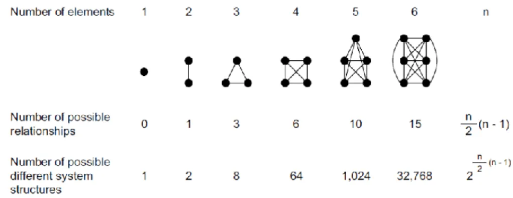
Flood and Carson (1993) define a system as “an assembly of elements related in an organized whole”, making immediately clear for the reader that its two distinctive properties are the number of elements that constitute it and the relationships that keep them together. The way in which they are mutually connected to each other describes the structure of the system.
Marti (2007) translating Patzak (1982) individuates in the number and types of both elements and relationships the determining factors causing complexity to arise.
Figure 12 - Visualization of the drivers for complexity of a system (Marti, 2007) from (Patzak, 1982)
Theoretical background
To better give an idea of how quickly the number of possible variants of a product can grow, it’s enough to think of a three-element system. Keeping the elements constant and assuming the relationships between them as bidirectional and boolean (present=1, absent=0), the system has 8 possible configurations. Doubling the number of elements, from 3 to 6, the number of possible system structures becomes 32˙768, more than 4˙000 times the result of the first case. (Marti, 2007) from (Flood & Carson, 1993)
Figure 13 - Example of elements, relationships, and system structures as a measure of complexity (Marti, 2007) from (Flood & Carson, 1993)
Each one of the elements and relationships in turn has specific qualities or properties, referred to as attributes, some of which can be changed to guarantee variety. (Flood & Carson, 1993)
Nowadays a product in order to be competitive in the market must be able to meet customer requirements in terms of specifications that generate the so-called external complexity. To satisfy the requests by adjusting the product’s attributes, developers introduce variety in the design. Variety, however, doesn’t affect just the product structure, but “spreads to all functional areas” of the manufacturing company, causing internal complexity. Of great interest is therefore to find the optimum combination between the creation of product variants and the additional cost associated with them. (Marti, 2007)
Figure 14 - Graphical representation of trade-off between costs and benefit associated with product variety (Marti, 2007) from (Rathnow, 1993)
Ulrich and Tung (1991) however, point out that variety is only appealing for customers if it enhances the functionality of the product, especially “in terms of the specific performance characteristics of the product relative to a particular functional element”. The indication on which attributes it’s necessary to change in order to meet a specific need can be found in the product architecture. (Ulrich & Tung, 1991)
Theoretical background
2.1.2
Mass customization
To resolve the conflict between uniformity and variety, economy of scale and economy of scope, an apparently oxymoronic concept has been introduced: Mass Customization, defined as “production and distribution of customized goods and services on a mass basis” (Davis, 1987)
The term mass customization was coined by Stanley Davis in his visionary work appropriately titled Future Perfect (1987) wherewith he subverted the industrial mindset of that time in the same way Einstein’s theories shook classical physics. The author develops this revolutionary concept from the application of science to business, as the former derives fundamental properties of the universe, whose comprehension makes them transferrable to the creation of products and services for the latter. (Davis, 1987) (Pine, 1993)
Possibly inspired by Einstein’s approach, he analyses three of the fundamental quantities of the universe, time, space and matter but from the point of view of industrial economy, with the aim of fundamentally transforming their meaning and the way in which they are perceived, from constraints to resources. (Davis, 1987) The breakup point with tradition lays in the switch from a producer centred to the new customer centred reference system: Davis (1987) summarizes the key points of this shift as any time, any place, no matter.
Emblematic of this attention towards the customer is the example with which this term was introduced, the customization of mass-produced shirts, challenging at the same time both the dichotomies of either/or and part/whole. Indeed, the fact that every one of the shirts is mass produced with the same specifications makes it a part of a whole batch, but since each one could be individually personalized already in the production line it becomes simultaneously a whole and a part of the whole. (Davis, 1987) (Pine, 1993)
Figure 15 - Mass produced monogrammed shirt wherewith Davis (1987) introduced the term Mass Customization
Consequently, the idea of mass market loses its meaning and, as Davis (1987) recognises, every customer is his own market. Pine (2011) goes one step further stating that “every customer is multiple markets” unfolding this concise proposition with the following example:
“Think of travel. If you travel for business, you want one thing from the
airline, the hotel, the rental car company, the restaurants you frequent, and so forth. Bring your spouse with you and suddenly all of those requirements change. Bring the kids along and they change again. Travel for pleasure, rather than for business, and each permutation mutates yet again.” (Pine,
Theoretical background
Piller and Kumar (2006) agree with Pine (2011), Victor and Boynton (1993) on the dangers of excessive variety to blindly pursue the maximum customization. “Customer satisfaction may not only plateau after a certain customization level of the product, it may decrease because of the frustration a customer feels due to excessive choice or variety.” (Piller & Kumar, 2006)
Toffler and Toffler (1970) used the term overchoice to identify this phenomenon and by reasoning on the worst possible scenario described a dystopian situation in which people are paralyzed in front of decisions by a surfeit of variety.
To avoid this hyperbolical effect, it is then necessary to develop “some sort of design tool” to help customers bring into focus their generally blurry needs without having to articulate it (Pine, 2011), set the best degree of customization (which is hardly ever the maximum) and define the mass customization specifics (Piller & Kumar, 2006), as “Fundamentally customers don’t want choice; they just want exactly what they want” (Pine, 2011).
2.1.3
Modularity
As emerged from the historical excursus introducing this section, the challenge for companies has nowadays become to offer their clients customizable and flexible products keeping at the same time prices in line with the ones of mass production. This prompts the question as to how to handle the deriving complexity (Schuh, Rudolf, & Vogels, 2014)
Finding the point of optimum balance between external variance and internal standardization is the main motivation behind the choice of a modular approach in the configuration of the product. (EY, 2015)
“If we want to perfectly understand a problem we must reduce it to its simplest terms and divide it up into the smallest possible parts.” (Descartes, 1619-1630)
Several centuries later, Clark and Baldwin (2000) open their book by suggesting the same strategy to manage complexity, introducing the concept of modularity. Extremely peculiar is the fact that their definition of modularity, has itself the same structure as the concept that it must convey. By readapting McClelland and Rumelhart (1986), Clark and Baldwin (2000) define modularity as the combination of two distinct ideas, whose sum is greater than the sum of its parts (Aristotélēs, IV century b.C): the first one being interdependence within and independence across modules, while the other incorporates abstraction, information hiding, and interface.
Designing a modular product then basically means conceive it as made up of discrete and mutually independent units that embody a specific abstract product task (function), this way dividing the complexity of the whole system and hiding it in each component. The standardization of the interfaces guarantees the integrability of the modules in the final structure, combining the functions while maintaining the independence of the structure. (EY, 2015) (Baldwin & Clark, 2000)
The term modulus takes its origin as a diminutive of modus (“measure”) and has initially been used as conventional unit of measurement for the proportioning between the various parts of a whole, were it the human body, ships or buildings. The term was formalised by Vitruvius in the third chapter of the fourth book of his opera De Architectura, reason why the term with this connotation is also referred to as Vitruvian modulus (Miller & Elgård, 1998)
The term remained mainly used in the fields of art and architecture, until Bauhaus, an architecture movement itself, introduced the aspect of interface compatibility to its meaning. The concept of module became closely linked to the idea of “building block”, intended to be a specific room, each of which could be connected to the others in
Theoretical background
different arrangements thanks to the standardised interfaces, in an attempt to rationalise geometries, allowing the usage of prefabricated materials to increase the efficiency during both the planning and construction phases. (Miller & Elgård, 1998) This formulation raised the interest of the mechanical world that decided to implement this approach to the design of products and machines to create variety the combination and exchange of different building blocks. (Miller & Elgård, 1998)
Figure 16 - Different types of building block systems (mainly according to size) (Miller & Elgård, 1998) after (Borowski, 1961)
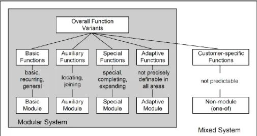
Miller & Elgård (1998) attribute to Pahl, Beitz, Feldhusen, and Grote (1996) the integration of functionality in the concept of module and the categorization of the latter on the base of the kind of function they embody, automatically excluding from the definition anything that cannot be assigned to these categories.
They distinguish type of function, importance, complexity, combination, resolution, concretization and application. (Miller & Elgård, 1998) citing (Pahl, Beitz, Feldhusen, & Grote, 1996)
Figure 17 - Function types and module types in modular and mixed product system (Miller & Elgård, 1998) after (Pahl, Beitz, Feldhusen, & Grote, 1996)
Albers, Burkardt, Sauter and Sedchaicharn (2008) define them as:
Basic functions: fundamental scopes of the product, not variable in principle.
Auxiliary functions: required for the connection of the various product’s components. Special functions: additional sub-functions related to specific product variants. Auxiliary functions: necessary for the adaptation of the product with the others.
Theoretical background
The tool that associates the functional structure to physical components in the product structure is the product architecture. (Ulrich, 1992)
Ulrich (1992) defines more rigorously product architecture as:
1. The arrangement of functional elements
2. The mapping from functional elements to physical components
3. The specification of the interfaces between interacting physical components
In order to derive the functional product structure, it is necessary to clearly state the main function of the product and then proceed top-down individuating the hierarchy of all the subfunctions that make up the product task, each one expressed in an abstract and solution-neutral way. (EY, 2015)
The physical components proposed to fulfil the various functions, are not necessarily a single hardware element, but can as well be subassemblies whose elements address a function altogether or even software subroutines. (Ulrich, 1992)
The degree of modularity is measurable through the morphology of the mapping, i.e. “the level of functional independence of the components and the interface standardization between different elements of the product structure”. (EY, 2015) Functional independence investigates the complexity of the relationships between functions and components. These relations can essentially be of two kinds:
• “one-to-one”: biunique relation between function and component (Ulrich, 1992) (EY, 2015)
• “non one-to-one”: complex mapping in which several functions are implemented by more than one component, and in which several components each implement more than one function (Ulrich, 1992)
Therefore, one product will be all the more modular, the more one-to-one relationships characterise its architecture. (EY, 2015)
The process of modularization indeed “is not a process to turn a non–modular into a completely modular product but it can be applied to increase the degree of modularity”. (Albers, Burkardt, Sauter, & Sedchaicharn, 2008) citing (Rapp, 1999)
Theoretical background
Another fundamental aspect in the analysis of the product architecture is the coupling / decoupling of the interfaces of the components, i.e. the extent the change of one component will affect all the components that interface with it in order to maintain the functionality of the while system unaffected. (Ulrich, 1992)
Figure 19 - Difference between de-coupled interface and coupled interface (Ulrich, 1992)
In the example in the picture, the eventual change of thickness of the bed would only affect the box in the system on the right (coupled interface), while, thanks to the nature of their connection, the one on the left would remain the same (decoupled interface). (Ulrich, 1992)
The constraints on interfaces do not only depend on the geometry though, considering that for the system to correctly perform, energy, information and material have to flow without obstacles on their way. (Ulrich & Tung, 1991) (Miller & Elgård, 1998)
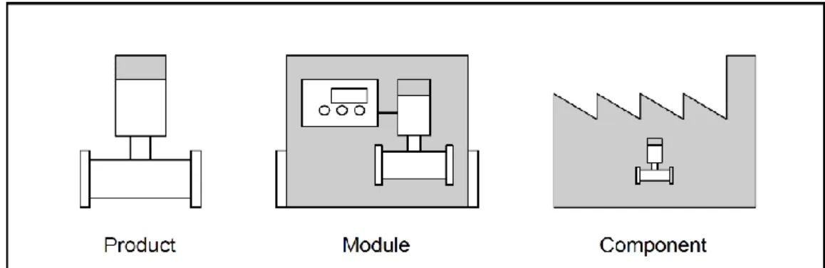
It is important to note that Ulrich and Tung (1991) describe modularity as a “relative property” since it can only be quantified in relation to other products. Furthermore, modularity is a principle that can be applied at several levels of the product as explained by Miller and Elgård (1998) with the recapitulatory scheme below, using the example of a flowmeter:
Figure 20 - Different perception of the same object during its lifecycle (Miller & Elgård, 1998)
1. The life cycle of the flowmeter starts at the manufacturing company, where it is seen as a product
2. It is then dispatched to a manufacturer of energy-meter for hot water, where it is used as a module, together with a processor and a temperature gauge.
3. Finally, when the energy meter is installed in a large process plant, the flowmeter becomes a component
To sum up the contents presented in this section so far, functional independence and standardized interfaces guarantee interchangeability of the constituent components consequently allowing to reach variety of products while at the same time reducing variety in manufacturing. (Ulrich & Tung, 1991) (EY, 2015)
Theoretical background
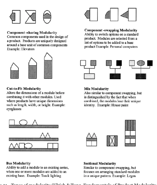
The image below displays the types of modularity presented by Ulrich and Tung (1991)
Figure 21 - Types of modularity (Ulrich & Tung, Fundamentals of Product Modularity, 1991)
To develop the perfect structure of the products, the R&D can resort to this scheme and even combine two or more of these approaches.
To conclude, using the wording proposed by Miller and Elgård (1998), the main drivers behind modularization result to be:
• Variety creation (customize)
Offer the customer differently tailored products combining standard modules • Use of similarities (reuse resources and standardize)
Reuse knowledge to speed up work, cut all redundancies, limit risks focusing on improving the stable solutions (modules) by reducing internal variety • Complexity Reduction
Enhance comprehension of the problem by diving it and resolving its subparts with different groups working in parallel
As a final note, it is essential to evaluate in each case the cost-benefit balance of such approach and to pursue “an optimal rather than maximal degree of modularity”. (EY, 2015)
Theoretical background
2.1.4
Standardization
The higher degree of variety reachable for instance through modularization, increases the internal complexity of the product, jeopardizing the performance of the whole production system and causing the costs to rise. (Perera, Nagarur, & Tabucanon, 2000) One way to reduce the number of variables maintaining the same level of variety is represented by standardization, since, as indicated by Agard and Kusiak (2004), this technique focuses on “the use of common components, products, or processes to satisfy heterogeneous needs”.
This approach is especially suitable in tandem with modularization, as not only does standardization aim to reduce the newly arisen internal complexity, but throughout the process of modularization, the function of each component as well as the interface of the component with the rest of the product has to be clearly defined, giving the instruments for the standardization of components on a functional base. (Ulrich & Tung, 1991)
The more standard the interfaces are, the higher level of interchangeability could be reached, allowing not just to swap different solutions for a specific product function, but even to use the same one or more components on different products. (Ulrich & Tung, 1991)
It has been proved that standardization improves efficiency by means of access to economy of scale and simplification of manufacturing processes. Agard and Kusiak (2004) show that standardization can reach different depths in the development of the product:
− Commonality of components in different products
− Standardization of components for comparable requirements
− Standardization of the manufacturing process (Agard & Kusiak, 2004)
Theoretical background
According to Ulrich and Tung (1991) the advantages of standardization include: • reduced component costs because of economies of scale in component
production,
• enhanced component performance arising from ongoing refinement, • broad amortization of product development costs,
• reduced materials management costs because of a reduction in part
numbers used in the production system.
While the choice of a standardized component could cause the following collateral costs: (Ulrich & Tung, 1991)
• a mismatch between ideal performance characteristics and those available
in standard components,
• an increase in unit costs arising from the use of a component with excess
(costly) capability.
With this premise, it is evident that the main drivers for standardization are grouping of functions in one component and cost reduction.
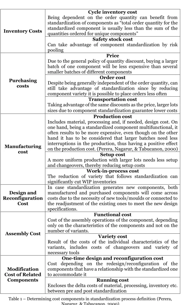
Perera, Nagarur and Tabucanon (2000) examine qualitatively the cost to be considered in the evaluation of which components to standardize as summed up with the chart in the next page.
The authors, as a concluding note underline the importance of logistic issues deriving from the supply of the component, suggesting a further evaluation of make or buy decision, manufacturing process and supplier choice in the light of the economic analysis just carried out.
Theoretical background
Inventory Costs
Cycle inventory cost
Being dependent on the order quantity can benefit from standardization of components as “total order quantity for the standardized component is usually less than the sum of the quantities ordered for unique components”
Safety stock cost
Can take advantage of component standardization by risk pooling
Purchasing costs
Price
Due to the general policy of quantity discount, buying a larger batch of one component will be less expensive than several smaller batches of different components
Order cost
Despite being generally independent of the order quantity, can still take advantage of standardization since by reducing component variety it is possible to place orders less often
Transportation cost
Taking advantage of the same discounts as the price, larger lots sizes due to component standardization guarantee lower costs
Manufacturing cost
Production cost
Includes material, processing and, if needed, design cost. On one hand, being a standardized component multifunctional, it often results to be more expensive, even though on the other hand it has to be considered that larger batches need less interruptions in the production, thus having a positive effect on the production cost. (Perera, Nagarur, & Tabucanon, 2000)
Setup cost
A more uniform production with larger lots needs less setup and changeovers, thereby reducing setup costs
Work-in-process cost
The reduction of variety that follows standardization can significantly cut WIP inventories
Design and Reconfiguration
Cost
In case standardization generates new components, both manufactured and purchased components will come across costs due to the necessity of new tools/moulds or connected to the readjustment of the existing ones to meet the new design specifications.
Assembly Cost
Functional cost
Cost of the assembly operations of the component, depending only on the characteristics of the components and not on the number of variants.
Variety cost
Result of the costs of the individual characteristics of the variants, includes costs of changeovers and variety of necessary tools
Modification Cost of Related
Components
One-time design and reconfiguration cost
Cost depending on the redesign/reconfiguration of the components that have a relationship with the standardized one to accommodate it
Running cost
Encloses the delta costs of material, processing, inventory etc. between pre and post standardization
Table 1 – Determining cost components in standardization process definition (Perera, Nagarur, & Tabucanon, 2000)
Theoretical background
2.1.5
Previous similar studies
Heuristic method
The heuristic method takes as starting point the functional decomposition of the product according to the type of flow (material, energy, signal) associated with it, adding the concept of functional dependency to “further arrange functional models with respect to time” (Stone, Wood, & Crawford, 1998). The order in which the functions must be performed can be sequential or parallel according to the same logic as for electricity flows. When one flow passes through all sub-tasks it is called sequential, whereas when all the tasks depend on a common sub-function while still being independent from each other it is defined parallel. (Stone, Wood, & Crawford, 1998)
The heuristic method comprehends three distinct approaches, all relying on the same flow basis.
1. Dominant flow: groups in a module all the sub-functions a flow encounters before leaving the system or being converted in a different kind of flow. (Stone, Wood, & Crawford, 1998)
Figure 23 - Dominant flow heuristic applied to a generic function structure (Stone, Wood, & Crawford, 1998)
2. Branching Flows: modules correspond to branches of parallel function chains. With this approach the product architecture enables component swapping and bus modularity (Stone, Wood, & Crawford, 1998)
Figure 24 - Flow branching heuristic applied to a generic function structure (Stone, Wood, & Crawford, 1998)
3. Conversion-Transmission Modules: combines in a module conversion
sub-functions or conversion-transmission pairs, i.e. those sub-functions which take as input a certain type of flow and turn it into another form of output flow. (Stone, Wood, & Crawford, 1998)
Theoretical background
Figure 25 - Conversion-transmission applied to a generic set of sub-functions
Downsides that prevented the choice of this method:
• the modules identified differ depending on the approach chosen
• “each of the methods may identify overlapping modules or modules which are subsets or supersets of other modules” (Stone, Wood, & Crawford, 1998)
Figure 26 – Example of the confusion in the choice between modules identified with the 3 heuristic approaches in the example of a SKIL Twist power screwdriver, adapted from (Stone,
Theoretical background
Design structure matrix
The Design Structure Matrix is a network modelling tool used to recognise modules in the system structure from groups of elements that have more internal than external interactions. (Eppinger & Browning, 2012) (Albers, Burkardt, Sauter, & Sedchaicharn, 2008)
The DSM is represented as a square N x N matrix, mapping the interactions among the set of N system elements. (Eppinger & Browning, 2012)
The DSM can be applied to several types of systems (product, organization, process), in the case of product architecture modelling “the elements would be the components of the product and the interactions would be the interfaces between them” (Eppinger & Browning, 2012).
The components are labelled in the leftmost column and the top row and the relationships between them are marked in the corresponding off-diagonal cells.
Figure 27 - Example of binary DSM (a) and its equivalent in diagraph form (b) (Eppinger & Browning, 2012)
Each off-diagonal mark in the matrix represents the output of the element in the corresponding column and the input of the element in that row, so proceeding column by column all the outputs of the heading element of the column can be seen while examining each row all the inputs to the heading element of the row are represented. The main advantage of the use of the DSM method is the ease of understanding, which thanks to the graphic representation in matrix form allows to represent even complex architectures in a compact and “intuitively readable” way. (Eppinger & Browning, 2012)
A confirmation of this fact can be seen comparing the DSM above with the chart below representing the same structure in an evidently less effective way.
Table 2 - Chart relationship representation
In the example the interactions were classified just as present or absent, but in different types of DSM charts the relations can be indicated by a numerical or symbolic weighting factor representing the number of relationships or their importance.
Element A B C D E F G H Inputs E D, F, G H A, B, F B E C E
Theoretical background
The technique to recognise the modules in the product structure through the analysis of the DSM is called clustering and consists in reordering the rows and columns to maximize the number and importance of interactions between adjacent elements in the DSM (Eppinger & Browning, 2012).
The goal of the clustering process is to isolate modules that have as many relationships as possible within them and as few as possible between them, so several iterations may be required.
The two main key factors that must be carefully balanced for a successful outcome of the modularization process are the dimensions of clusters and the number of interactions outside them. Eppinger and Browning (2012) indeed propose the following expression for the objective function to be minimized for the clustering analysis:
𝑂𝑏𝑗 = 𝛼 ∑𝑀𝑖=1𝐶𝑖2+ 𝛽𝐼𝑜 (1
)
Where Ci is the size of the cluster, Io the number of outer interactions and α and β weighting factors.Additional aspects to be considered comprehend:
• Interaction types: interactions can be traced back to four main types (spatial proximity, material flow, information flow and energy transfer) and depending on the relative weight given to each of them, different sets of clusters can be individuated for the same structure. (Eppinger & Browning, 2012)
• Integrating elements: elements that remain unassigned to any of the clusters due to the variety of components they interact with act as integrative components in bus modularity architectures (Eppinger & Browning, 2012)
Figure 28 - Composite DSM including spatial, energy, information, and material interactions (left) compared to its clustered form (right) (Eppinger & Browning, 2012)
Downsides that prevented the choice of this method:
• heavily influenced by the importance attributed to each type of interaction, generating results not consistent over time (Eppinger & Browning, 2012) • overlapping clusters (Eppinger & Browning, 2012)
• even though it is always possible to manually rearrange the elements, for the clustering to be effective complex systems require the use of commercial software or macros. (s0me examples on DSM Conference (2019))
Method and implementation
3 Method and implementation
3.1 Research design
To perform the study commissioned for this thesis work, the research course represented in the flowchart below has been followed.
Method and implementation
The research object of this paper has been carried out adopting an interpretivist approach, grounded on the collection and subsequent analysis of data to derive rules and knowledge. Interpretive approaches rely on inductive reasoning to gain understanding (Kroeze, 2012) “in areas with no or insufficient a priori theory” (Bhattacherjee, 2012). In contrast with positivism, where research questions are used for theory testing, the inductive approach uses them to “narrow the scope of the study” (Gabriel, 2019). In this method, the research work, starting from data, aims to build “a theory about the phenomenon of interest from the observed data” (Bhattacherjee, 2012), consequently this research work can be divided in three main stages:
1. Prestudy 2. Data collection 3. Data analysis
For each of which several methods and techniques (described more in detail later on in this chapter) have been employed.
The term prestudy refers to the gathering of background information necessary to frame the research and provide directions for the way forward, before getting into the central theme of the paper.
The first step, once established the purpose of the project, was the acquisition of a general view of the context of the research work, i.e. the concepts of modularization and standardization and their implications.
For this reason, even before physically being in the company, an extensive literature research has been carried out to gain an insight on the existing approaches to the topic, inspecting relevant publications, websites and course literature.
Once in the company, another piece of background information necessary for the project has been collected: the external perspective. As prompted by Schuh, Rudolf and Vogels (2014) the market analysis was used to identify the initial field of observation and market segments. This investigation comprehends technical similarities with competitors, customer fields, new competitors and innovations as well as price ranges, regions and usage. (Schuh, Rudolf, & Vogels, 2014)
The next phase was the collection of data directly significant for the scope of the research. The material gathered concerns all stages of the of the product development process: identification of customer needs and expectations, commercial offer and definition of the architecture of the system. The sources were respectively clients and the company’s employees dealing with them, historical records of Ficep’s commercial offers and dossiers on handling systems already realized and Ficep’s experienced product managers and designers in cooperation with Trennitalia’s expertise and knowledge. The methods used in this process were brainstorming, to obtain the full spectrum of customer requests straight from the interested parties, case studies and interviews, to look for patterns in the translation of the requests into technical specifications of the system, the relationships between technical specifications and physical characteristics of the elements of the handling system and the rules for their configuration.
All the information assembled in the previous phase was then analysed with the scope of deriving a new product architecture. The methods used in consecutive order were functional decomposition to subdivide the functionalities of the whole handing system into functions of the individual units that make them up, Function-means tree analysis to assign the functions to constituent modules, the interface analysis through which the interdependencies of the modules are used to standardize the interfaces between them to guarantee interchangeability and set the performance to remain the same. To structure this knowledge a configurator has been created using Excel as base software and, being the distribution of translator arms a linear optimization problem, the built in Solver tool has been included in the computation routine. Automatizing the definition of constraints (self-adapting on the base of the input specifics) and launch of the solver through the coding of macros allowed the individuation of the optimal
Method and implementation
3.2 Prestudy
3.2.1
Literature research
The first stage in a research project is the definition of the context and the background for the study and the best way to start gaining acquaintance with the topic is to perform a literature research on it. This procedure involves analysing and synthetizing the conceptual literature as well as articles, completed research reports, theses, conference papers and all the relevant material about the topic under investigation (Williamson, 2002). Exploring the information directly connected to the topic of the study can also widen the horizons of the researcher, leading to serendipical discoveries beyond the specific field of study and uncover links between subjects useful in the subsequent practical applications of the theory examined. (Williamson, 2002)
The exploration of the topic in literature includes the selection and articulation of the research questions to be investigated in relation to the object of interest of the research. All actions from that point onward will indeed be aimed at seeking answers to the research questions chosen. (Bhattacherjee, 2012)
Unlike positivist approach, in which the research questions are formulated as hypotheses to be validated using empirical data, in interpretivist research designs the research questions state the area in which new theory will have to be derived from data (e.g. what, why, how, when, etc.) (Bhattacherjee, 2012).
3.2.2 Market and competitors’ analysis
Ficep customers are either builders of structural steel structures that work on contracts for large infrastructure projects and carry out the entire process, or their subcontractors, outsourcing partners specialized in carrying out the machining of beams and profiles they are subcontracted for.
The main applications can be: − Industrial buildings
− Residential buildings (skyscrapers)
− Other public buildings (e.g. stadiums, arenas, etc.) − Offshore structures
− Telecommunication towers and transmission infrastructures − Bridges and other major infrastructures
Figure 30 - Examples of Ficep customers’ applications (courtesy of Ficep)
Ficep's reference market is mainly foreign, where over 90% of turnover is realized, and extra-European where 80% of turnover is realized. It is therefore important to investigate the situation of the competitors on a global scale.