Architectural software patterns and maintainability: A case study
(HS-IDA-EA-01-105)
Fredrik Hoffman (a98freho@student.his.se) Department of Computer Science
University of Skövde, Box 408 S-54128 Skövde, SWEDEN
Final year project in Systems Programming, spring 2001. Supervisor: Henrik Jacobsson
Architectural software patterns and maintainability: A case study Submitted by Fredrik Hoffman to Högskolan Skövde as a dissertation for the degree of B.Sc., in the Department of Computer Science.
2001-06-07
I certify that all material in this dissertation which is not my own work has been identified and that no material is included for which a degree has previously been conferred on me. Signed: _______________________________________________
Architectural software patterns and maintainability: A case study Fredrik Hoffman (a98freho@student.his.se)
Abstract
The importance of building maintainable software is being recognized in the community of software development. By developing software that is easy to maintain, the time and resources needed to perform the modifications may be decreased. This will in turn mean economical savings and increased profits.
Architectural software patterns are said to promote the development of maintainable software. The aim of this project was therefore to investigate whether architectural software patterns possess this property or not. A case study was performed where two candidate architectures were compared using a method called Architectural analysis of modifiability. This method uses change scenarios and modification ratios to identify differences between candidate architectures. A system developed at Ericsson Microwave Systems AB was used for the case study.
One of the candidate architectures consisted of two architectural software patterns: the Layers pattern and the Model-View-Controller pattern. The architecture analysis showed that the Layers pattern did promote maintainability whereas the Model-View-Controller pattern did not, from the basis of judgement associated with the method.
Keywords: software patterns, maintainability, software architectures, software architecture analysis.
Table of contents
1
Introduction ...1
2
Software architecture...2
2.1 Definition of software architecture... 2
2.2 Multiple views... 3
2.3 Documenting software architecture... 4
2.4 The purpose of using software architectures ... 5
2.4.1 Communication among stakeholders ... 6
2.4.2 Early design decisions ... 6
2.4.3 Transferable abstraction of a system ... 6
2.5 Scenario-based software architecture analysis ... 6
3
Software quality attributes...8
3.1 What is meant by software quality? ... 8
3.2 The quality attributes... 8
3.2.1 Attributes observable by execution ... 8
3.2.2 Attributes not observable by execution ... 8
3.3 Software architecture and maintainability... 9
4
Software patterns ...11
4.1 What is a software pattern? ... 11
4.1.1 Architectural patterns ... 11
4.1.2 Design patterns ... 12
4.1.3 Idioms... 12
4.2 Properties of software patterns ... 12
4.3 An architectural pattern example ... 13
4.4 Related – styles and frameworks... 14
5
Problem definition ...16
5.1 Software maintenance ... 16
5.2 Problem description... 17
6
Method...19
6.1 Approaches... 19
6.2 Software architecture analysis ... 20
6.3 Method specification ... 21
6.3.1 Get to know ComSim... 22
6.3.2 Describe the existing architecture of ComSim... 22
6.3.3 Describe a new pattern-based architecture ... 22
6.3.4 Elicitation of change scenarios... 22
6.3.5 Evaluate the change scenarios ... 22
7
Results...24
7.1 Getting to know ComSim... 24
7.2 Describing the existing architecture of ComSim ... 24
7.3 Describing a new pattern-based architecture of ComSim ... 27
7.4 Elicitation and selection of change scenarios... 32
7.4.1 Scenario I – Simulation of multiple units... 32
7.4.2 Scenario II – Implementation of dynamic message handling... 32
7.4.3 Scenario III – Implementation of message history handling ... 32
7.5 Evaluation of the change scenarios ... 32
7.5.1 Scenario I – Simulation of multiple units... 33
7.5.2 Scenario II – Implementation of dynamic message handling... 33
7.5.3 Scenario III – Implementation of message history handling ... 33
7.6 Interpreting the results from the scenario evaluation ... 34
8
Analysis...36
8.1 Analysis of the existing architecture ... 36
8.2 Analysis of the new pattern-based architecture... 36
8.3 Differences between the existing and the new architecture ... 37
8.3.1 Structural differences ... 37
8.3.2 Differences exposed by change scenarios ... 38
9
Conclusions ...40
9.1 Results ... 40
9.2 Discussion ... 41
9.3 Future work ... 42
9.3.1 Other aspects of maintainability of architectural software patterns ... 42
9.3.2 Carefully prepared software corresponds to software patterns ... 43
9.3.3 Using software patterns promote maintainability but worsens performance 43 9.4 Visions... 43
1 Introduction
1
Introduction
The importance of maintainability and reusability is significant for software engineering today. According to Lientz and Swanson (1980) approximately 50 to 70 percent of a systems total cost is in the maintenance phase, i.e. after it was initially delivered. Bass et al. (1998) estimate that the maintenance phase contributes up to 80 percent of the total cost of the system, which in turn means that most developers work with systems in the maintenance phase. It is therefore important that systems are well documented and well structured to be able to support change, since this decreases the efforts needed to meet changes in the requirements, the functional specification or the system environment. To accomplish good structuring, developers should design software architectures. Hofmeister et al. (2000) say that by modeling software architectures, the software developer take early design decisions and plan actively to try to meet the system’s requirements. These requirements are often expressed as software quality attributes; maintainability is an example of such a software quality attribute.
The structure, or the architecture, of the software is of vital importance to be able to maintain the software. Maintaining the software could involve activities such as increasing or decreasing functionality, adjusting the software to satisfy new requirements, adapting it to newer technologies or correcting errors and bugs.
Extending functionality or adapting software with poor architecture and inconsiderate solutions may be very difficult and time-consuming. This will be even worse if the documentation is insufficient. According to Buschmann et al. (1996), the use of software patterns in developing software systems may reduce these problems, by providing well-proven solutions and a way of forwarding the original intentions that led to the architecture design. Further, they say that the use of software patterns supplies the people involved in the software development with a basis for discussing solutions using standard concepts, but also to complement the documentation of the software system. And last, but not least, according to Buschmann et al. (1996) patterns for software architecture explicitly consider non-functional aspects, e.g. changeability and reusability.
Prechelt et al. (1998) find it interesting to investigate how software with software patterns compare to software without. They say: “[…] how does maintenance compare for software with patterns versus equivalent software without?” (Prechelt et al., 1998, p13). It would therefore be interesting to investigate how architectural software patterns affect a system’s maintainability, since maintainability is largely related to the system’s architecture (Bass et al., 1998). Will the use of architectural software patterns in software architecture design promote maintainability? The aim of this project is to find an answer to this question, by performing a case study.
At Ericsson Microwave Systems AB (EMW) in Skövde the importance of software architecture has recently attracted much attention. There is therefore a certain interest in investigating the benefits from using software patterns in the software architecture design. This is why this project is performed in cooperation with EMW.
2 Software architecture
2
Software architecture
Software architecture is an unexplored area, and as Hofmeister et al. (2000) put it: “Unfortunately, software architecture is still very much an emerging discipline within software engineering” (Hofmeister et al., 2000, p.3). This chapter gives an introduction to software architecture, first by defining software architecture. In section 2.2, the theory of multiple viewpoints of software architecture is explained. The following sections deal with documentation of software architectures and the benefits from applying system architecture. The last subsection gives a brief introduction to software architecture analysis.
2.1
Definition of software architecture
What does the expression software architecture really mean? Bass et al. (1998) point out that, since the discipline of software architecture is relatively young, there is no single accepted definition of the term software architecture. There are a lot of different opinions present. The definitions are somewhat equal at the core; they handle the structural and runtime properties of a system. Clements and Northrop say: “[Software architecture] is a focus on reasoning about structural issues of a system” (Clements & Northrop, 1996, p. 3). This definition puts its focus on the static viewpoints of the system. Beck and Johnson give the following straightforward definition; “An architecture is the way the parts work together to make the whole” (Beck & Johnson, 1994, p. 1). This definition is more about dynamic, or runtime, issues of the system. According to Shaw and Garlan “The architecture of a software system defines that system in terms of computational components and interactions among those components.” (Shaw & Garlan, 1996, p. 3). They continue by specifying the interactions between the components as connectors, which could be procedure calls, protocols, pipes etc. However, this definition is also principally concerned with the runtime behavior of the system.
The definitions mentioned so far are not very thorough, but broad. The following, more detailed, definition is presented by Bass et al. (1998, p. 23):
The software architecture of a program or computing system is the structure or structures of the system, which comprise software components, the externally visible properties of those components, and the relationships among them.
This definition is also emphasizing the structural issues of a software system. Bass et al. (1998) are precise when they point out that software architecture hides details about the system, and that it is the properties visible from outside the components that are of interest. Thus, the architecture is an abstraction, hiding information not interesting at this level. This means that information about a component that does not pertain to its interactions should be omitted, according to Bass et al. (1998). They continue by stating that the primary building blocks of an architecture is the components and the connectors, which is the same viewpoint that Shaw & Garlan present. Bass et al. (1998) mean that a
2 Software architecture
components. So, they do not explicitly talk about runtime behavior in their definition, but they say that connectors perform runtime functions.
Hofmeister et al. (2000) consider the software architecture to be a design plan – a blueprint – of the system. They elucidate the expression design plan as a “[…] structural plan that describes the elements of the system, how they fit together, and how they work together to fulfill the systems requirements.” (Hofmeister et al., 2000, p. 4). This definition is more relevant, since it handles both the static and the dynamic aspects of the software system. Moreover, it emphasizes the fulfillment of system requirements. This definition will be used in this report, since it handles both the structural (static) and runtime (dynamic) aspects of the software system, and the meeting of requirements. These aspects lead on to the next section, which handles the need for multiple views to be able to fully describe a software system.
2.2
Multiple views
According to Kruchten (1995) there exist different stakeholders in the development of software systems. These stakeholders could be for instance; end-users, developers and project managers. All of these stakeholders have different knowledge and interest in the software system, and as Bass et al. put it; “[A] software exhibits many structures, and we cannot communicate meaningfully about it unless it is clear which structure we are describing.” (Bass et al., 1998, page 36). They continue by saying that a software system consists of both static (structural) and dynamic (runtime) properties. Because of this the need for different views of a software system arises. Kruchten (1995) therefore introduces the 4+1-view model of software architecture.
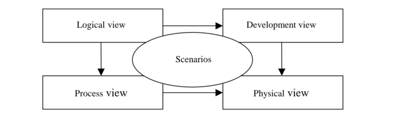
In this model Kruchten (1995) proposes the following views:
The logical view the object model of the system. This view is used to depict the functional requirements of the system at an abstract level. This view also emphasizes the interaction between entities in the system, and is often described by using a class diagram.
The process view captures the concurrency and synchronization aspects of the design. This view puts its focus on the runtime behavior of the system, i.e. the behavior of processes in the system, e.g. how objects are created and how they communicate.
The physical view describes the mapping of the software onto the hardware and is also concerned with distributed aspects, i.e. how processes are distributed on computers in a network.
The development view shows the static organization of the software in the development environment, which is concerned with how the components in the systems are organized.
Kruchten’s additional “+1-view” is set up of scenarios that shows how the four other views are related and how they work together. Kruchten (1995) presents the following figure (Figure 2-1) to show how the different views are related:
2 Software architecture
Figure 2-1. The 4+1-view (Kruchten, 1995, p. 2).
Bass et al. (1998) have further developed the ideas of multiple views. They present nine different views that they regard to be the most common and useful ones. However, they do admit that their views are closely related to Kruchten’s 4+1-views.
Hofmeister et al. (2000) found, in a study of large complex industrial software systems, that software architecture has four distinct views. They say that these views help people to manage complexity, and allow addressing higher priority decisions first. The four views that Hofmeister et al. (2000) found in their study are also very similar to Kruchten’s 4+1-view model.
It is clear that there is a need for multiple views to be able to fully describe a software system, but it should also be noted that not all systems need to be described with all the views. According to Hofmeister et al. (2000), Bass et al. (1998) and Kruchten (1995), views in small systems might be so similar that they can be described together. Whereas in larger systems the difference between views become more obvious.
2.3
Documenting software architecture
As noted in the previous section, software architectures should be modeled in multiple views. How should this be done and what notation should be used? Bass et al. (1998) propose a box and line-type notation. However this notation does not spring from any standards. Hofmeister et al. (2000), on the other hand, use UML1, which at recent years has become a de facto standard. There will be no examples of these modeling techniques in this report; the reader is referred to Hofmeister et al. (2000). It should be emphasized that the use of UML is preferable since it is a widespread standard. As Chris Kobryn points out, “Using this de facto standard saves us from learning yet another specification language and allows us to focus on the subject matter instead of splitting notational and semantic hairs about what boxes and lines mean.” (Hofmeister et al., 2000, foreword).
Development view Physical view Process view Logicalview Scenarios
2 Software architecture
2.4
The purpose of using software architectures
Why is it important to design software architectures? According to Hofmeister et al. (2000) the software architecture serves as an abstraction that helps the developers to manage a systems complexity. This is accomplished by encapsulating details into architecture elements, such as components. The software architecture is, according to Hofmeister et al. (2000), a bridge between the requirements and the implementation. Gacek et al. (1995) mean that since the software architecture support the needs of all kinds of stakeholders e.g. customers, users, developers and maintainers, the software architecture is involved throughout the software systems whole lifetime. In figure 2-2, the software architecture is closely related to all the activities in the software system’s lifecycle. In fact, the software architecture could be seen as the hub that all the development activities are connected to.
Figure 2-2. Software Architecture involvement lifecycle (Gacek et al., 1995, p. 7).
Gacek et al. (1995) continue by stating that the software architecture is the key milestone in the system’s lifecycle. They emphasize that a software project should not proceed into full-scale development until a software architecture has been designed.
Bass et al. (1998) say that the importance of software architecture is to ensure good software quality (software quality is further explained in section 3.1), but they are also convinced that the software architecture alone would not guarantee system quality. “A good architecture is necessary, but not sufficient, to ensure quality.” (Bass et al., 1998, page 32). They recognize three major areas of interest related to software architectures, namely:
• Communication among stakeholders
• Early design decisions Requirements Design Implementation Testing Maintenance Software Architecture Integration
2 Software architecture
• Transferable abstraction of a system
In the following three subsections these areas are further explained. 2.4.1 Communication among stakeholders
As noted in section 2.2 there exist different stakeholders in the software development process. These stakeholders need different views to address their special aspects of the system. Bass et al. (1998) say that the software architecture will provide for a means of communication between the different stakeholders, allowing mutual understanding. 2.4.2 Early design decisions
The software architecture embodies the earliest design decisions. These decisions are according to Bass et al. (1998), the hardest ones to get right, the hardest ones to change and the ones that have the largest impact on the software system and its development. This is because it is in the architecture design phase that the foundation, for how well the system will meet its desired quality attributes, is laid. Furthermore, according to Bass et al. (1998), the components in the software architecture are usually used to group development teams.
2.4.3 Transferable abstraction of a system
Bass et al. (1998) and Gacek et al. (1995) propose that reuse at the software architecture level is the highest level of reuse. They say that the earlier reuse is applied in the development cycle the bigger the benefits. It is clear that reuse of code is beneficial, but reuse at architectural level will give further benefits. “[…] reuse at the architectural level provides a tremendous amount of leverage for systems with similar requirements.” (Gacek et al., 1995, p. 8).
2.5
Scenario-based software architecture analysis
How does one know whether a software architecture is good or bad, according to its requirements? If it would not be possible to determine if the software architecture meet its requirements, then it would, according to Clements and Northrop (1996), be rather hazardous to choose the right architectural solution from the start. It would be very costly to realize in the middle of the implementation that the whole system needs to be reorganized. This is why there are a number of different methods to analyze the software architecture, before it has been implemented. This report will focus on the methods using scenarios for evaluation, since they are fast and relatively easy methods, compared to other methods, i.e. formal analysis.
Bass et al. (1998) propose the Software Architecture Analysis Method (SAAM) for software architecture analysis. In this method the software systems quality attributes are evaluated (the software quality attributes will be further presented in chapter 3). This is accomplished by creating domain specific scenarios that reflects qualities of interest. The method will then contrast candidate architectures from how well they fulfill the scenarios applied. For further information about this method the reader is referred to Bass et al. (1998). The SAAM has been refined into the Architecture Tradeoff Analysis Method
2 Software architecture
used to identify areas of potential risk, sensitivity points and trade-off points within the software architecture. See Kazman et al. (2000) for additional information on the ATAM. Bengtsson et al. (2000) suggest a method for software architecture analysis of modifiability. This method is also based upon scenarios, and its aim is threefold. Bengtsson et al. (2000) recognize three different goals for performing an architecture analysis of modifiability, namely:
• Maintenance cost prediction: estimate the effort needed to accommodate changes.
• Risk assessment: identifying changes not supported by the software architecture.
3 Software quality attributes
3
Software quality attributes
This chapter deals with software quality attributes. The first subsection declares what is generally meant with software quality. Section 3.2 discusses the different quality attributes used, and section 3.3 discusses the quality attribute maintainability in the context of software architecture.
3.1
What is meant by software quality?
The expression software quality is concerned with how well the system meets its requirements, i.e. how well it meets its users need. But how should this be measured? It would not be enough to say that a system meets its requirements. Different users may have different needs, which could be differently fulfilled. Barbacci et al. give the following definition of software quality: “Software quality is the degree to which software possesses a desired combination of attributes” (Barbacci et al., 1997, p. 1). This is why software quality is measured with different attributes – software quality attributes – which are the subject of the next section.
3.2
The quality attributes
Bass et al. (1998) call attention to that there are mainly two types of quality attributes, namely attributes that are:
• Observable by execution.
• Not observable by execution.
These types of attributes is briefly presented in the two following subsections. 3.2.1 Attributes observable by execution
Bass et al. (1998) identify attributes observable at execution time as those attributes that corresponds to how well the system meets its behavioral requirements. They identify these attributes as the following:
Performance corresponds to how well the system responds to stimuli.
Security is the measure of how well the system resists unauthorized usage, but still provides service to legitimate users.
Availability represents the measurement of the length of time between failures. Functionality is the ability of the system to do the work it was intended to do. Usability is related to how well the system supports the user of the system. 3.2.2 Attributes not observable by execution
According to Bass et al (1998), attributes that are not observable by execution time are e.g. related to modifying and testing the software system. The following attributes are pertained to these topics:
3 Software quality attributes
Modifiability refers to the ability to make changes to the system, and how functionality is divided. The system should support quick and cheap change.
Portability is related to how easy it is to have the system run on different platforms.
Reusability corresponds to designing the system so that it is possible to use parts of it in future software systems.
Integrability describes the ability of the components to work correctly together. Testability represent with which ease the system can be tested for finding
faults.
All of these attributes are not totally applicable at the software architecture. Bass et al. (1998) take as an example, the attribute usability. How easy an interface is to use is not related to the software architecture. However, there are other attributes, such as modifiability, that are largely related to software architecture.
3.3
Software architecture and maintainability
The quality attribute modifiability mentioned earlier is very closely related to maintainability. Lientz and Swanson (1980) classify maintainability to consist of three parts, namely: modifiability, understandability and testability. Bengtsson et al. (2000) have a similar opinion. Bengtsson et al. (2000) point out that modifiability is a subset of maintainability, and that maintainability adds the correction of bugs to the topics related to modifiability. They give the following definition of modifiability: “The modifiability of a software system is the ease with which it can be modified to changes in the environment, requirements or functional specification.” (Bengtsson et al., 2000, p. 3). Bass et al. (1998) say that from the point of view of achieving maintainability and modifiability via architectural means, they are the same. Since this report puts it focus on the level of software architecture, modifiability and maintainability will be treated synonymously.
Buschmann et al. (1996) have their own viewpoint upon maintainability. They consider the non-functional property changeability to consist of: maintainability, extensibility, restructuring and portability. On the other hand, Bass et al. (1998) mean that modifiability consists of: extendibility, portability, restructuring and deletion of unwanted capabilities. As discussed in the previous paragraph, Bass et al. (1998) consider maintainability and modifiability to be synonymously, whereas Bengtsson et al. (2000) believe that modifiability is a subset of maintainability. This is an equation that is not very easy to solve. However, by comparing the viewpoints of Buschmann et al. (1996) and Bass et al. (1998), changeability and modifiability should be considered to be the same. Since it was stated earlier in this report that modifiability and maintainability will be treated synonymously in this project, this relation is extended with changeability. This report will therefore consider maintainability, modifiability and changeability to be the same, from an architectural viewpoint. Modifiability is, according to Bass et al. (1998), also very closely related to some other quality attributes, e.g. reusability. They consider reusability
3 Software quality attributes
and modifiability to be two sides of the same coin; systems built to be modifiable are also reusable.
Bass et al. (1998) recognize the following categories of change: Extending or changing functionality, deleting unwanted functionality, adaptation to new operating environment or restructuring. Bass et al. (1998) show that software architecture partition the changes into three categories, namely:
Local changes where a change affects a single component.
Nonlocal changes concerned with changing multiple components, but leaving the architecture intact.
Architectural changes that affects fundamental component interaction, requires change all over the system.
Bass et al. (1998) emphasize that, since the local changes are the easiest to perform, the software architecture should be modeled in such a way that the changes most likely to occur are the easiest to make.
4 Software patterns
4
Software patterns
This chapter deals with software patterns. The first subsection defines what a software pattern is, and different software pattern categories. Section 4.2 describes the benefits from using software patterns, and the following chapter gives an example of an architectural software pattern. The last subsection of this chapter deals with expressions closely related to architectural software patterns.
4.1
What is a software pattern?
What is a software pattern? Buschmann et al. (1996) give the following description: “A pattern addresses a recurring design problem that arises in specific design situations, and presents a solution to it” (Buschmann et al., 1996, p. 5). This description states that a software pattern is a general solution, possible to apply to similar, specific problems. According to Gamma et al. (1995), a software pattern describes the core solution to a specific problem, but offers the ability to adjust the solution to the problem at hand. It should be stated that software patterns do not offer fully detailed solutions. Buschmann et al. (1996) call attention to that software patterns provide a scheme for a generic solution to a family of problems, and cannot be used “as is”. Further, software patterns do not replace the use of software development methods, i.e. RUP2. Instead, software patterns should be used in conjunction with these methods.
Buschmann et al. (1996) recognize three different categories of software patterns, since they cover various ranges of scale and abstraction. The three categories mentioned are the following:
• Architectural patterns
• Design patterns
• Idioms
The following subsections will describe these different abstraction levels of software patterns.
4.1.1 Architectural patterns
Architectural patterns are used as templates for software architectures. The following definition is given by Buschmann et al. (1996, p. 12):
An architectural pattern expresses a fundamental structural organization schema for software systems. It provides a set of predefined subsystems, specifies their responsibilities, and includes rules and guidelines for organizing the relationships between them.
Buschmann et al. (1996) emphasize that one single software pattern is not enough to describe software architectures. Several combined software patterns may be needed to design a complete framework for the software architecture. Buschmann et al. (1996) point
2 RUP (Rational Unified Process), the reader is referred to Kruchten P., (2000). The rational unified process. Reading, Mass. : Addison-Wesley
4 Software patterns
out though, that it takes experience to know what software patterns to combine. They say that the selection of a certain software pattern should be driven by the software system properties, since different software patterns support different properties. In Buschmann (1999), guidelines for how to design a software with the help of software patterns are presented.
4.1.2 Design patterns
Design patterns are used to describe smaller architectural units, and the relationships between them. Design patterns are defined by Buschmann et al. (1996, p. 13) as follows:
Design patterns are medium-scale patterns. They are smaller in scale than architectural patterns, but tend to be independent of a particular programming language or programming paradigm. The application of a design pattern has no effect on the fundamental structure of a software system, but may have a strong influence on the architecture of a subsystem.
Observe that design patterns, like architectural patterns, are independent of what programming language or what programming paradigm that is used. They are general enough, according to Buschmann et al., to be implemented in an object-oriented fashion, as well as in a procedural style. Gamma et al. (1995) are, on the other hand, convinced that design patterns should be used in object-oriented manners.
4.1.3 Idioms
Idioms are the lowest level of software patterns, and are related to both design and implementation. Buschmann et al. (1996, p. 14) defines idioms like this:
An idiom is a low-level pattern specific to a programming language. An idiom describes how to implement particular aspects of components or the relationships between them using the features of the given language.
As noted by this definition, idioms are not as general as design patterns. Idioms are concerned with how to solve a specific problem in a specific programming language.
4.2
Properties of software patterns
Software patterns provide general solutions to design problems in software development. Are there any benefits from using software patterns? Buschmann et al. (1996) state that there are several advantages in using software patterns.
According to Buschmann et al. (1996) and Gamma et al. (1995), software patterns provide a means to reuse the design knowledge gained by experienced software developers. Thus, making it possible to reuse successful and well-proven solutions. Software patterns put its focus on practicability, meaning that software patterns should describe well-known solutions to recurring problems rather than the latest scientific results.
4 Software patterns
be easier, since lengthy and complicated descriptions would not be necessary. A software pattern name can be used to explain which parts of a solution that corresponds to which component in the software pattern. The developers would, of course, have to be acquainted with the software patterns mentioned.
Buschmann et al. (1996) mean that software patterns support the documentation of the software system. Software patterns provide a way of forwarding visions that led to an architecture, this helps developers to avoid violating these visions in the maintenance phase. Beck and Johnson (1994) agree to this, by saying that software patterns mediate the decisions that led to a design.
Buschmann et al. (1996) say that software patterns support software complexity management. A software pattern describes what components, and their relationships, that are needed to solve the problem it addresses. There is no need to invent a new solution to the problem, if there is a software pattern that describes it. Shaw and Garlan make the following remark: “Original designs are much more rarely needed than routine designs.” (Shaw & Garlan, 1996, page 7). A software pattern offers a standardized way to solve a problem; it has been proved to do the job. If there is a working solution at hand, why invent the wheel all over again?
Finally, Buschmann et al. (1996) say that patterns for software architecture explicitly consider non-functional aspects, i.e. changeability and reusability, of which the aspect changeability is treated synonymously with maintainability in this report (see section 3.3).
4.3
An architectural pattern example
Every software pattern underlies a three-part schema, recognized by Buschmann et al. (1996). The three parts are:
• Context - concerns the situation in which the problem arises.
• Problem - defines the recurring problem in the context.
• Solution - describes how to solve the recurring problem.
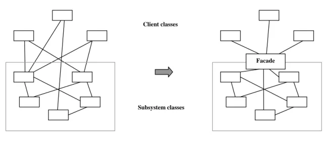
Buschmann et al. (1996) extend this schema with some additional information, e.g. name, example, structure and implementation. For a complete list, see Buschmann et al. (1996). Below the Model-View-Controller pattern is introduced. It is taken from Buschmann et al. (1996), but is not presented in its entirety. Some parts have been omitted, e.g. implementation examples and scenarios, and those parts that are present have been simplified. However, this description should give a feeling for how a software pattern is described. For a fully detailed description the reader is referred to Buschmann et al. (1996). Examples of other architectural software patterns are Layers, Blackboard and Pipes-and-filters.
Name Model-View-Controller
Context Interactive applications with a flexible human-computer interface.
Problem User interfaces is especially prone to changing requests. These changes could be to modify menus when new functionality is added. If the user
4 Software patterns
interface is closely interwoven with the functional core it would be expensive and error prone to introduce changes.
Solution Divide the application into three areas: processing, output and input.
• The model component encapsulates core data and functionality.
• The view components display information to the user. There can be multiple views obtaining their information from the model.
• The controller, one per view, receives input, usually as events. These events are translated to service requests, and are sent to either the model or to the view. The controller is therefore the component to which the user communicates.
This solution allows changing a subsystem without causing major effects to the other subsystems.
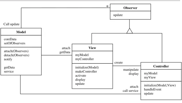
Structure
Figure 4-1. Structure of the MVC-pattern (Buschmann et al., 1996, p. 129).
Notice in the figure (Figure 4-1) the parent class Observer, it defines the update interface common to View and Controller. The Observer class corresponds to the Observer pattern, introduced in Gamma et al. (1995).
4.4
Related – styles and frameworks
Closely related to architectural software patterns are architectural styles and frameworks. This subsection tries to straighten things out.
Both Bass et al. (1998) and Hofmeister et al. (2000) are using the expressions
Controller myModel myView initialize(Model,View) handleEvent update View myModel myController initialize(Model) makeController activate display update Model coreData setOfObservers attach(Observers) detach(Observers) notify getData service Observer update Call update attach getData create manipulate display attach call service *
4 Software patterns
recognize a slight difference, and prefers to separate them. They say that software patterns are more problem-oriented than architectural styles. Buschmann et al. (1996) do, however, admit that architectural styles are very similar to architectural software patterns, and say that every architectural style can be expressed as an architectural pattern. This report will use the phrase architectural software pattern, since it is the most common and accepted expression.
According to Buschmann et al. (1996), a framework is a partially complete software system. This implies that a framework is not as general as an architectural software pattern. A framework is devoted to a specific domain or platform and is generally implemented in a particular language, whereas a software pattern is not restricted to a certain domain or platform and described in a language independent manner. Buschmann et al. (1996) point out that a framework may consist of software patterns, but the opposite can never be true.
5 Problem definition
5
Problem definition
This chapter puts this project into a broader perspective and motivates the importance of it. Further, this chapter defines the aim of this project.
5.1
Software maintenance
As mentioned in the introduction of this report, a system’s major cost is in the maintenance phase. Lientz and Swanson (1980) found in a survey that 50 to 70 percent of a systems total cost is in the maintenance phase, while Bass et al. (1998) estimate the maintenance cost to approximately 80 percent. It is easy to understand that everything that would speed up and simplify this activity should imply large economical savings. Gacek et al. (1995) estimate that about 47 percent of the maintenance efforts are related to software system understanding. The importance of system understanding cannot be neglected, since if the system is not understood, the risk of destructive changes increase. What ways of reducing cost and workload in the maintenance phase are there? Parnas (1994) and Buschmann et al. (1996) propose the following guidelines for enhancing maintainability: accurate documentation, intense reviewing, preserving structure when introducing changes and design for change in advance. This means that it is important to have a thorough and correct documentation of the software system to facilitate understanding. This will give maintainers a possibility to preserve the software architecture. It is also important that, when changes occur, the documentation is updated according to the changes made. Finally, Parnas (1994) and Buschmann et al. (1996) emphasize that the design of the software architecture should take future changes under consideration. Bass et al. (1998) support this statement, they say that “[…] an effective architecture is one in which the most likely changes are also the easiest to make.” (Bass et al., 1998, page 33). To summarize, the major means for reducing cost and workload in the maintenance phase are flexible architectures developed with future changes in mind and good documentation that facilitate understanding.
How does one construct flexible architectures that supports maintainability? According to Buschmann et al. (1996), software patterns support the construction of software with defined properties and design for change. They say, “patterns explicitly address nonfunctional requirements for software systems, such as changeability, reliability, testability or reusability” (Buschmann et al., 1996, p. 7). Furthermore, Buschmann et al. (1996) emphasize that software patterns are a means of documenting software architectures. They say that software patterns forward architectural vision, which helps developers in the maintenance phase to preserve the software architecture. Beck and Johnson (1994) agree to this, they say that the use of software patterns mediates the reasons for the design solutions made, and why they were made that way. The software patterns used would, of course, have to be described in the documentation. The point is that when the intentions that resulted in the software architecture are accessible to the maintainer, it will be easier to understand and preserve the software systems architecture.
5 Problem definition
quite costly to find out that the software system does not support maintainability when it is modified for the first time. This is why there are methods for analyzing software architectures, before they are implemented. The earlier system requirements can be evaluated, the lesser the time spent in development and the bigger the economical savings. As noted in chapter 2.5 there has been a lot of research in this area. Bass et al. (1998) and Bengtsson (2000) are examples of researchers that have put a lot of efforts in finding a way to evaluate software system requirements at the architectural level. They both propose a scenario-based evaluation of the requirements, which they prefer to speak of as the quality attributes. Maintainability is an example of such a quality attribute.
5.2
Problem description
Software patterns are said to promote maintainability. Are software patterns proved to have this property? Though to all the books and articles written in the subject, none of them reference to any scientific report that states the positive properties of software patterns. However, a recent report, Prechelt et al. (2000), does try to investigate what benefits software design patterns have upon maintainability. The focus in Prechelt et al. (2000) is at software design patterns, the benefits from using architectural software patterns is not dealt with. In another paper, Prechelt et al. (1998), they say in the future work section that: “Finally, and perhaps most interestingly, how does maintenance compare for software with patterns versus equivalent software without?” (Prechelt et al., 1998, p13).
To answer this question Prechelt et al. (2000) choose to investigate how design patterns affect maintainability. They studied a group of software developers when they performed modifications to small pieces of software. Prechelt et al (2000) found that unless there is a clear reason for not using a design pattern, the flexibility introduced by the design pattern is advantageous because of unexpected changes in the requirements. Prechelt et al. (2000) mention implementation overhead as a reason for not using design patterns. Since maintainability is largely determined by its architecture (Bass et al., 1998), it would be interesting to evaluate the impact on maintainability introduced by architectural software patterns.
As noted in the introduction, EMW are interested in architectural software patterns. This project is performed in cooperation with EMW, since there is a system available for case study purpose there. EMW feel that this is an interesting area that needs further investigation. They are aware of the cost associated with maintainability, and are interested in simplifying this phase.
The aim of this project is to evaluate the actual gain from using architectural software patterns when modeling software architectures, with respect to maintainability. A case study will be performed where two different software architectures will be compared; one modeled with architectural software patterns and the other one modeled ad hoc, or at least not using architectural software patterns. Of course, these two software architectures should have the same specification of requirements. The problem of this project is therefore to find an answer to the following question: Will the use of architectural software patterns promote maintainability? The expected result of this study should be
5 Problem definition
that a pattern-based architecture should promote maintainability in a better way than an equivalent architecture without patterns.
There are some prerequisites for the project. Only the architectural software patterns in Buschmann et al. (1996) will be used. If there will be design patterns needed to describe the architecture of possible subsystems or to complement the architectural software patterns, those design patterns from Buschmann et al. (1996) and Gamma et al. (1995) will be considered. There are different aspects of maintainability, as discussed in section 3.3. It is decided to focus on the changing part of maintainability, since there are architecture analysis methods for evaluating this aspect of maintenance. Lientz and Swanson (1980) categorize understandability as another aspect of maintainability, but understanding will not be evaluated.
The candidate architecture that best supports modifications is considered to be the most maintainable. If the pattern-based architecture is the one that best supports maintenance, then architectural software patterns will be considered to promote maintainability.
6 Method
6
Method
This chapter deals with how the problem of evaluating the effects that architectural software patterns have on maintainability is to be investigated. First, some different approaches to deal with the problem are discussed, resulting in the selection of an approach. Then some architecture analysis methods are compared, which results in the selection of the analysis method to be used in this project. In the last section the method to be used in this project is specified.
6.1
Approaches
One approach to investigate the problem could be to make a literature study. Since there are a lot of books and articles in the subject area, this would be possible. However, the literature written in the subject area does not refer to any research in the topic. To give the literature study some additional weight, it could be complemented with interviews of how some different software companies uses architectural software patterns and what consequences they have experienced from this. The problem with this approach would be to find companies that are using architectural software patterns when they model software architectures. Furthermore, since software architecture is an “emerging discipline” (Hofmeister et al., 2000, p.3), it may even be difficult to find companies that models software architectures at all. The advantage of this approach would be that it gives an overall picture of the community of software development viewpoints on the consequences from using architectural software patterns.
Another, perhaps more interesting, approach would be to fully implement two systems from the same specification of requirements, one modeled with architectural software patterns and the other one modeled in ad hoc manners, or at least not using architectural software patterns. A set of changes should be made to both the systems, and then an evaluation of which one of the systems that best support the changes could be made. However, this procedure would be much too expensive in terms of time and efforts needed.
To save time and effort, an alternative approach could be evaluation of change support made at the architectural level. This would be possible since a system’s maintainability is largely determined by its architecture (Bass et al., 1998). By comparing two candidate architectures with an architecture analysis method, no implementation is needed. This procedure would be much more economical with concern to time and efforts needed. The drawback would, of course, be that this alternative would not be as reliable as the previous approach. Rather, this evaluation would be built on assumptions and estimations about relationships and solutions not visible at the architectural level.
Because of the limitations associated with this project and the problems associated with the literature study, the last of the proposed approaches will be performed, i.e. an architectural analysis.
6 Method
6.2
Software architecture analysis
There are alternative ways to do a software architecture analysis, e.g. formal methods or scenario-based methods. However, formal methods are quite complicated. First the architecture must be described in a formal description language, and then the formal analysis method may be applied. This formal approach is too complicated to fit into the boundaries of this project.
As described in section 2.5 there exist scenario-based software analysis methods. These methods are easier to perform and understand than formal methods. Furthermore, they are rather quick to perform, and therefore fit the limitations of this project. In section 2.5 three different methods were presented, the SAAM (Software Architecture Analysis Method), the ATAM (Architecture Tradeoff Analysis Method) and Analyzing software architectures for modifiability (hereafter noted ASAM). The SAAM and the ATAM are used to analyze all the quality attributes of interest, whereas the ASAM method is concerned with modifiability only.
As noted in section 3.3, modifiability and maintainability are treated synonymously. The scenario-based analysis method that is to be used in this project is the ASAM method, developed by Bengtsson et al. (2000). Since this method is concerned with modifiability only it fits the purpose of this project.
Bengtsson et al. (2000) recognize three goals for performing software architecture analysis for modifiability, namely:
• Maintenance cost prediction: estimate the effort needed to accommodate changes.
• Risk assessment: identifying changes not supported by the software architecture.
• Software architecture selection: selecting the most optimal candidate architecture. Bengtsson et al. (2000) propose different procedures and techniques depending on the goal for performing the analysis. Lassing et al. (2000) emphasize the importance of making sure that there is one clear goal set for the analysis, combining the techniques is far from trivial. Even though all of the goals, proposed by Bengtsson et al. (2000), are interesting, one of the goals has got to be selected. The goal that best fits the purpose of this project should be the software architecture selection. The purpose of this goal is to find the software architecture that best supports future maintenance, which is exactly the intention of this project.
Having the goal set for the architecture analysis, the following steps in a software architecture selection are proposed by Bengtsson et al. (2000):
1. Describe software architecture: describe relevant parts of the software architecture. For candidate comparison at least two different architectures are needed. According to Bengtsson et al. (2000), the information of interest is the following:
6 Method
• Lower level design and implementation.
• Relationship to system environment.
Bengtsson et al. (2000) emphasize that not all the relationships and dependencies are visible in the software architecture. This is because some of these relationships and dependencies are introduced in lower level design and implementation. If this information is not yet available, assumptions will have to be made about the relationships and dependencies. This will, of course, affect the accuracy of the analysis. If there are change scenarios that require adaptation to the environment, there should be information about the system’s relationships to the environment available in the architecture description.
2. Elicit scenarios: find a set of relevant change scenarios. For candidate comparison, only those scenarios that expose differences between the architectures are selected. To be able to find the right scenarios, different stakeholders should be interviewed. This is because finding the relevant scenarios requires domain and system knowledge.
3. Evaluate scenarios: determine the effects of the scenarios applied. Bengtsson et al. (2000) propose a component modification ratio, where, for each scenario, the total number of components in the architecture divides the number of modified components.
4. Interpret the results: draw conclusions from the analysis results, and choose the most change supportive architecture.
Bengtsson et al. (2000) emphasize that since the software architecture evolves during architecture design, the amount of information available for analysis purposes depends at the point in time at which the architecture analysis is performed. The analysis will of course be more correct if more information is available.
To be able to describe a system’s architecture in this project, either a new system will have to be modeled or an existing system could be used. At EMW there is a system available for this purpose. The system is called ComSim and is presented in section 7.1.
6.3
Method specification
In this section the method to be used in this project is presented. The method is largely based on the architecture analysis method proposed by Bengtsson et al. (2000). The method consists of the following six steps:
1. Get to know ComSim.
2. Describe the existing architecture of ComSim. 3. Describe a new pattern-based architecture.
4. Elicit and select change scenarios applicable for both architectures. 5. Evaluate the change scenarios.
6 Method
Each step is explained in more detail in the following subsections. 6.3.1 Get to know ComSim
To be able to describe the architecture of the system, domain and system knowledge is needed. To support the learning phase there are some resources available. There is the code, a class diagram and a specification of requirements available. The best resource though, is that the developers that constructed the system are available for interviews and discussions. Above this, there is also the possibility to study the system at execution. 6.3.2 Describe the existing architecture of ComSim
In this step the architecture of ComSim is to be described. As noted there is a specification of requirements available. In addition there is a class diagram showing all of the classes and their relations, but there is no software architecture description available. This step is therefore concerned with raising the level of abstraction, moving from the class diagram to a software architecture, describing components and their relationships. 6.3.3 Describe a new pattern-based architecture
A candidate architecture, based on architectural software patterns, should be modeled in this step, using the guidelines in Buschmann (1999) and the architectural software patterns described in Buschmann et al. (1996). The description of the new pattern-based architecture, and the existing one, should use the UML notation, because of reasons discussed in 2.3. Before proceeding to the elicitation of scenarios, both the architectures should be verified by the developers of ComSim.
6.3.4 Elicitation of change scenarios
The Elicitation of change scenarios consist of two phases. The first phase is concerned with finding change scenarios, and the second phase deals with selecting the change scenarios that are most interesting to evaluate. The elicitation of change scenarios should be done in collaboration with the developers of ComSim. This is because they have a better understanding of the system and the domain of ComSim. It is worth emphasizing that the scenarios to be elicited should be relevant, meaning that there must be a possibility that these changes will be performed in the future.
6.3.5 Evaluate the change scenarios
In this step the scenarios elicited in the previous step should be applied to both candidate architectures. For each of the scenarios the components affected directly by the change scenario, but also components affected indirectly, should be identified. The developers of ComSim should review the evaluation of the architectures, to confirm the accuracy of it. 6.3.6 Interpret the results
Bengtsson et al. (2000) propose different measurement methods for each of the goals presented in section 6.2. For candidate comparison the number of affected components, for each scenario, should be divided by the total number of components in the architecture. This will give a component modification ratio for each scenario and
6 Method
problem with this method, when there are few components in the candidate architectures or when small changes are performed. Consider the following example.
An architecture analysis is performed with two candidate software architectures A and A’. Architecture A consists of two components and A’ is modeled with three components. A future change is identified and requires one component to be modified in both the candidate architectures. Suppose that the change is quite simple and is only concerned with modifying one single class in both the architectures. Following the measurement method proposed by Bengtsson et al. (2000), architecture A will get a modification ratio of 1/2 and A’ a modification ratio of 1/3. This condition is quite misleading, since the change scenario is concerned with modifying one class only in both the candidate architectures.
Because of this the modification ratio will be extended, the number of changed classes for each change scenario and candidate architecture should be estimated as well. Since this project is using an existing system, it should be possible to identify the number of classes that are affected from applying a change scenario. By calculating the number of modified classes it will be possible to identify misleading modification ratios.
7 Results
7
Results
This chapter presents how the method, specified in the previous chapter, was applied to the problem. Each of the steps in the specified method is presented in the following subsections.
7.1
Getting to know ComSim
ComSim was not developed with any specific software pattern in mind. However, this does not exclude the possibility that there are software patterns present. Since the system was developed by experienced developers, solutions that correspond to software patterns might have been used.
ComSim is a verification tool for hardware components in the radar system Erieye, developed at EMW. As the name implies, ComSim simulates communication in Erieye. This means that ComSim is able to simulate different hardware components in the radar system, which simplifies testing of the operator interface. ComSim is also used for registration purpose, meaning that it is used for recording and replaying communication in the radar system.
ComSim is written in the Java programming language. This is because ComSim should be possible to run in both Windows NT and Solaris platforms. The system consists of at least 35.000 lines of code. In addition, there is a lot of code generated with the help of CORBA3. The graphical user interface is developed with the help of Visual Café4.
System knowledge was accomplished largely by studying the class diagram and the code. However, interviews and discussions with one of the developers gained the initial and broad insight to how the system worked and was constructed. Moreover, he was available throughout the learning phase for question.
7.2
Describing the existing architecture of ComSim
Throughout the learning phase it was possible to distinguish two components in ComSim. This was because the graphical user interface (GUI) was strictly separated from the system’s functionality (called COM), following the principles of the Facade design pattern from Gamma et al. (1995). The developers verify this approach, they confirm that the major issue was to separate the GUI from the system’s functionality. The functionality of ComSim is accessible through one class, called Message. Thus, the Message class forms the facade of the COM component, which makes it easier to use according to Gamma et al. (1995).
It was decided to represent the architecture of ComSim in a layered way, even though it would mean only two layers. Thus, the GUI forms the topmost layer of the application, allowing the operator to view and control the message traffic. The lowest layer is the actual simulator, i.e. the COM component, concerned with holding IP-addresses of other
7 Results
hardware units in the network, the storage of messages and for sending and receiving the messages in the form of byte streams, using UDP (User Datagram Protocol). This gives the following architecture (figure 7-1):
Figure 7-1. First architecture draft.
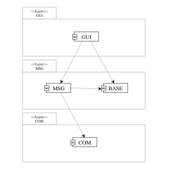
However, by studying the class diagram and the code further, it was found possible to split the COM layer into two separate layers, a message layer and a communication layer. This was possible since the UDP communication is separated from the message handling, but also because they represent to different levels of abstraction. This means that the COM component will be split into a MSG component, responsible for handling messages, and a COM component that is responsible for sending and receiving byte streams. Furthermore, there is a component responsible for holding the templates for the messages that are to be sent or received. This template makes it possible to transform a byte stream into a message and vice versa. Both the GUI and the MSG component use this message template component. This component is called base message (BASE) and is inserted in the middle layer. These modifications result in the following architecture (figure 7-2):
Figure 7-2. Second architecture draft.
Even though the COM layer is connected to the BASE component in the middle layer (figure 7-2), there is no relation between them. Thus, to emphasize the relations in the architecture an alternative viewpoint is presented in figure 7-3, where the relations between components are clearer. Note that the software architecture is described in one view only, i.e. the logical view (Kruchten, 1995). As discussed in section 2.2, a software architecture should be modeled in multiple views. Since ComSim is a rather small system and the analysis is concerned with maintainability only, there is, according to Bengtsson et al. (2000), no need to describe the architecture with any additional views. This is because maintainability is not so much concerned with the runtime behavior or the
GUI COM GUI MSG COM BASE
7 Results
distribution of processes. The notation used in figure 7-3 is a mix-up of the UML notation used by Rational Rose5 and the notation proposed by Hofmeister et al. (2000). The reason for this is that Hofmeister et al. (2000) introduce modules in the module view, which corresponds to Kruchten’s (1995) logical view. The modules proposed by Hofmeister et al. (2000) consists of one or more components, so the difference is not very dramatic. Instead of using the modules described in Hofmeister et al. (2000), the component notation used in Rational Rose is applied.
Figure 7-3. Proposed software architecture of ComSim. The arrows indicate dependency.
Buschmann et al. (1996) and Bachmann et al. (2000) present a few rules that distinguish a layered architecture from a non-layered architecture. Preferably, components should use only those components in the layer directly beneath. For efficiency reasons, however, relaxation to this rule is allowed, resulting in a relaxed layered architecture (Buschmann et al., 1996). In a relaxed layered architecture a component is allowed to use components
<<Layer>> GUI <<Layer>> MSG <<Layer>> COM MSG GUI BASE COM
7 Results
in all layers beneath. Furthermore, it is imperative in a layered architecture that there are no components that are using components in a higher layer (Bachmann et al., 2000). As can be seen in figure 7-3, both these rules are fulfilled.
However, a closer look at the code reveals that knowledge of the object to receive the message in the MSG component is hard-coded into the COM component. Resulting in that, on receiving a message, the COM component uses the MSG component to put messages into the received message buffer. These circumstances ties the MSG component and the COM component together, violating the meaning of layers. Since this is the only “upward-uses” relation it should be considered to be an exception. Thus, the existing architecture of ComSim should still be considered to consist of three layers.
An alternative way of solving the “upward-uses” problem would have been to use the same method that is used in the MSG component to notify the GUI when a new message has arrived. The MSG component implements a callback handler. The objects in the GUI that need to know when a new message has arrived, register themselves at the callback handler in the MSG component. At the arrival of a new message the callback handler in the MSG component notifies all the registered objects in the GUI, which themselves fetch the message from the MSG component. This strategy corresponds to the Observer design pattern in Gamma et al. (1995). A similar approach could have been used in the COM component for notifying the MSG component on message arrival, partitioning the MSG component and the COM component.
7.3
Describing a new pattern-based architecture of ComSim
Using a layered approach for the software architecture of ComSim is a natural solution, because the very nature of ComSim situates components in different levels of abstraction. Everything from high-level graphical user interfaces to low-level byte transmission. There is no reason to change this concept, and therefore the alternative, architectural software pattern based architecture will be designed with the Layers pattern (Buschmann et al., 1996, pp. 31-51) in mind.
Furthermore, since ComSim is an application with an interactive user interface and multiple views dependent of the same data, the Model-View-Controller (MVC) (Buschmann et al., 1996, pp. 125-143) pattern may also be suitable. This means that the new pattern-based architecture should be designed combining the MVC pattern and the Layers pattern. The structures of these architectural software patterns is presented in figure 7-4 and 7-5.
The layered structure is quite simple and straightforward, whereas the MVC pattern may be a little more confusing. The major issue is to separate the GUI from the functionality. The Model is responsible for the functionality and the data, whereas the GUI is separated in two parts. The View is responsible for updating the user interface and the Controller performs action on user events.
7 Results
Figure 7-4. Structure of the Layers pattern Figure 7-5. Structure of the MVC pattern
These two patterns may be combined in several alternative ways; two of these alternatives are presented in this report. The first alternative is to start with the MVC pattern and then to partition the Model component into layers. This approach is visually presented in figure 7-6.
Figure 7-6. Combination of the MVC and the Layers patterns.
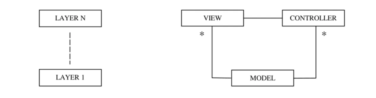
The second alternative would be to start off with the Layers pattern and integrate the MVC pattern into the layered structure. The resulting architecture could look something like figure 7-7.
Which one of these approaches to choose would be quite troublesome to decide. However at this stage in the project a desired future change is known, namely to be able to simulate more than one hardware unit at a time on one computer. To be able to do this, it must be possible to have several MSG components running. However, due to limitations in the transmission protocol it is not possible to have more than one COM component per machine, meaning that several MSG components have to share a common COM component. This knowledge makes the selection easier. To be able to have several MSG
MODEL VIEW CONTROLLER * * LAYER 1 LAYER N VIEW CONTROLLER * * MODEL LAYER 1 LAYER N
7 Results
architecture alternatives is suitable, since the first alternative would associate one COM component per MSG component.
Figure 7-7. Combination of the Layers and the MVC patterns.
To preserve the rules of the Layers pattern, the notification of incoming messages should be performed by the principles of the Observer design pattern in the new alternative architecture. This functionality has to be implemented in three components, namely COM, BUFFER and MSG. Buschmann et al. (1996) has another name for the Observer pattern, they prefer to call it the Publisher-Subscriber design pattern, however it is still the same software pattern. This metaphor may be easier to understand. The structure of the Observer pattern is presented in figure 7-8.
Figure 7-8. Structure of the Observer pattern (Gamma et al, 1995, p. 294). <<LAYER N-1>> VIEW CONTROLLER MODEL * * <<LAYER N>> <<LAYER 1>> Subject attach() detach() notify() getState() setState() subjectState observers[] Observer update() observerState subject *
for all o in observers { o->update() }
observerState= subject->getState()

![Figure 7-8. Structure of the Observer pattern (Gamma et al, 1995, p. 294). <<LAYER N-1>>VIEWCONTROLLERMODEL**<<LAYER N>><<LAYER 1>>Subjectattach()detach()notify()getState()setState()subjectStateobservers[]Observerupdate(](https://thumb-eu.123doks.com/thumbv2/5dokorg/3389180.20989/34.892.123.775.840.1047/structure-observer-viewcontrollermodel-subjectattach-getstate-setstate-subjectstateobservers-observerupdate.webp)