Postadress: Besöksadress: Telefon:
Box 1026 Gjuterigatan 5 036-10 10 00 (vx)
An experimental investigation of a
crossover concept for high accuracy indoor
positioning systems
Andreas Lind
MASTER THESIS 2015
INFORMATICS
Postadress: Besöksadress: Telefon:
This exam work has been carried out at the School of Engineering in
Jönköping in the subject area Master of Science with a major in Informatics, specialisation Information Engineering and Management. The work is a part of the Master of Science programme.
The authors take full responsibility for opinions, conclusions and findings presented.
Examiner: Vladimir Tarasov Supervisor: Rob Day
Scope: 30 credits (second cycle) Date: 2015-06-18
Abstract
To know your whereabouts is important and sometimes exact position is the determinant of success or not. Since the launch of the USA made Global Positioning System (GPS) in the late 1970s, global tracking has been available both for military and civilian use. Today, satellite based systems like the American GPS, European Galileo and the Russian GLONASS are the standard for basically any navigation or location application. However these systems are limited by the fact that they must have connection with multiple satellites in order to work. This means that satellite dependent systems are very limited in indoor environments. Despite this, there is no standard for indoor positioning systems (IPSs) even close to the satellite dependent systems when it regards distribution and accessibility for use where satellite dependent systems are limited or not working. However, this new age of connectivity provides a number of options for positioning indoors. There are some systems available, but very few of them provide good enough accuracy.
This Master thesis evaluates different options for indoor positioning using technologies that are available in smart devices and smart phones, such as Wi-Fi and Bluetooth, and focuses on indoor positioning systems that can provide high accuracy. The current state of the technologies and the possible future for them, considering rising need and interest in indoor positioning systems are covered in this thesis. A selection of technologies and approaches are explored, tested in conditions designed for this purpose and evaluated to highlight their differences in approach, accuracy and usability.
In order to achieve the goals of this thesis, a hybrid method of experimental research design and system development is selected as the main research method. The hybrid method is focused on experimental research, and is used to investigate if the accuracy of the positioning data can be affected and improved by tuning independent variables in an IPS. To be able to do this, an application for smart devices, such as android smartphones, is developed. The application developed is the heart of the conceptual crossover IPS (CCIPS), which is named Locantis, that is being developed and used in the experimental stages of this investigation. It is also used to test the hypothesis that a CCIPS could be a valid contender for replacing the established IPSs.
The observations show how the accuracy and precision of the location data is affected by change to independent variables in an IPS and how well a CCIPS can meet real time requirement’s.
The main conclusion is that changes to independent variables have greater impact on the precision than the accuracy for location data in an IPS and that a CCIPS in many cases are the sensible choice of IPS.
Sammanfattning
Att veta var du befinner dig är viktigt och ibland är exakt position avgörande för framgång. Sedan lanseringen av amerikanska Global Positioning System (GPS) i slutet av 1970 har global navigation varit tillgängliga för både militärt och civilt bruk. Idag är satellitbaserade system, som det amerikanska GPS, europeiska Galileo och det ryska GLONASS, standard för i princip alla navigering eller platsinformation. Men dessa system är begränsade av det faktum att de måste ha kontakt med flera satelliter för att fungera. Detta innebär att satellitberoende system är mycket begränsad i inomhusmiljöer. Trots detta finns det ingen standard för inomhus positioneringssystem (IPSS) som kan mäta sig med de
satellitberoende systemen när det gäller distribution och tillgänglighet. Men denna nya generationens kommunikation ger ett antal alternativ för positionering
inomhus. Det finns IPS tillgängliga idag, men väldigt få av dem kan tillhandahålla en hög noggrannhet på positioneringen.
Detta examensarbete utvärderar olika alternativ för inomhuspositionering med teknologier som är tillgängliga i smarta enheter och smarta telefoner, som Wi-Fi och Bluetooth, fokus ligger på inomhus positioneringssystem som kan ge hög noggrannhet. Det aktuella läget för dessa teknologier och dess möjliga framtid, med tanke på stigande behov och intresse av inomhus positioneringssystem, behandlas i detta examensarbete. Ett urval av teknologier och metoder utforskas, testas under förhållanden utformade för detta ändamål, och utvärderas för att lyfta fram sina skillnader i tillvägagångssätt, noggrannhet och användbarhet.
För att uppnå målen i detta examensarbete har en hybrid metod för experimentell designforskning och systemutveckling valts som huvudsaklig forskningsmetod. Hybridmetoden fokuserar på experimentell forskning och används för att undersöka om positioneringsdatas noggrannhet kan påverkas och förbättras genom att förändra oberoende variabler i ett IPS. För att kunna göra detta har en applikation för smarta enheter, så som Android, utvecklats. Applikationen som utvecklats är hjärtat i det konceptuella kombinations inomhuspositioneringssystem Locantis som utvecklas och används i det experimentella stadiet i denna
undersökning. Den används också för att testa hypotesen att en CCIPS kunde vara en giltig kandidat för att ersätta den etablerade IPSer.
Observationerna visa hur noggrannhet och precision av positioneringsdata
påverkas av förändring på oberoende variabler i ett IPS och hur väl ett CCIPS kan uppfylla realtidskravet talet.
Huvudslutsatsen är att förändringar på oberoende variabler har större inverkan på precision än noggrannheten för lokaliseringsuppgifter i en IPS och att ett CCIPS i många fall är det klokt val av IPS.
Keywords
Bluetooth Low Energy, BLE, Indoor-positioning system, HAIP, Network centric, Mobile centric, Android, Locantis
Acknowledgments
I would like to thank Ulf Björkman and Benny Saxén at Saab Training & Simulation in Huskvarna. You have given me a lot of valuable input. You have inspired me to look further and have made me feel welcome at Saab.
I would also like to thank Rob Day, who has been my thesis supervisor. You have spent a lot of your time discussing ideas and possibilities with me, which means a lot for me as a single student writing a thesis without partner. Our discussions and you feedback has made this thesis better.
Abbreviations
API – Application Programming Interface BT – Bluetooth
BTT – Bluetooth Technology BLE – Bluetooth Low Energy
CCIPS – Conceptual crossover Indoor Positioning System HAIP – High Accuracy Indoors Positioning
IDE – Integrated Development Environment ILA – InLocation Alliance
IR – Infra Red
ISM – Industrial, Scientific and Medical MC – Mobile Centric
MCHAIP – Mobile Centric High Accuracy Indoor Positioning System NC – Network Centric
NCHAIP – Network Centric High Accuracy Indoor Positioning System SIG – Special Interest Group
GATT- Generic Attribute Profile GPS – Global Positioning System IPS – Indoor Positioning System PAA- Phased Array Antennas RF – Radio Frequency-based RQ – Research Question RR – Request Rate
RSSI – Receiver Signal Strength Indicator SHF – Super High Frequency
TS – Training & Simulation UDP – User Datagram Protocol UHF – Ultra High Frequency
UNII – Unlicensed National Information Infrastructure URL – Uniform Resource Locator
Contents
1
Introduction ... 10
1.1 BACKGROUND ... 10
1.2 PURPOSE AND RESEARCH QUESTIONS ... 11
1.3 DELIMITATIONS ... 12
1.4 OUTLINE ... 13
2
Theoretical background ... 14
2.1 TECHNOLOGIES ... 14
2.1.1 Wireless network (Wi-Fi) ... 14
2.1.2 Bluetooth ... 15
2.1.3 Bluetooth Low Energy ... 15
2.2 POSITIONING TECHNIQUES ... 23
2.3 STANDARDS FOR IPS USING BLE ... 23
2.3.1 High Accuracy Indoor Positioning (HAIP) ... 24
2.3.2 Centralised... 26
2.3.3 Distributed ... 26
2.4 THE CCIPS ... 26
2.5 EMBEDDED SENSORS IN SMARTPHONES... 26
2.6 PRECISION, ACCURACY AND GRANULARITY ... 28
2.7 SIMULATIONS ... 30
2.8 EXERCISE MODEL ... 31
3
Method ... 32
3.1 EXPERIMENTAL RESEARCH DESIGNS ... 32
3.2 SYSTEM DEVELOPMENT ... 33
4
Implementation ... 34
4.1 APPLICATION DEVELOPMENT ... 34 4.1.1 Locantis ... 34 4.1.2 Embedded sensors ... 36 4.1.3 Communication ... 38 4.2 EXPERIMENTAL RESEARCH ... 38 4.2.1 Experimental set up ... 38 4.2.2 Experimental design ... 404.2.3 Experiment 1: Delta time 1 ... 41
4.2.4 Experiment 2: Delta time 2 ... 43
4.2.5 Experiment 3: Estimation accuracy and precision ... 46
4.3 RELIABILITY OF MEASURES ... 48
4.4 VALIDITY ... 49
5
Findings and analysis ... 50
5.1 DIFFERENCE BETWEEN CENTRALIZED AND DISTRIBUTED SIMULATION SYSTEMS ... 50
5.2 IMPACT ON CURRENT EXERCISE MODELS ... 50
5.3 DELTA TIME1 ... 51
5.3.1 Observations on 2Hz tag configuration. ... 52
5.3.2 Observations on 5Hz tag configuration ... 53
5.3.3 Observations on 9Hz tag configuration ... 54
5.3.4 Observations on 9Hz two-tag combo configuration ... 55
5.4 DELTA TIME 2 ... 57
5.4.1 Observations on Locantis with 1Hz request rate ... 58
5.4.3 Observations on Locantis with 4Hz request rate ... 60
5.5 ESTIMATION ACCURACY AND PRECISION ... 61
5.5.1 2Hz single tag configuration... 62
5.5.2 5Hz single tag configuration... 63
5.5.3 9Hz single tag configuration... 64
5.5.4 9Hz two-tag configuration ... 65
5.5.5 2Hz, 5Hz, 9Hz and 9Hz-combo configurations... 66
5.5.6 Estimated error ... 67
6
Discussion and conclusions ... 70
6.1 DISCUSSION OF METHOD ... 70 6.1.1 Theoretical ... 70 6.1.2 Practical ... 70 6.2 DISCUSSION OF FINDINGS ... 72 6.2.1 RQ1 ... 72 6.2.2 RQ2 ... 73 6.2.3 RQ3 ... 74 6.2.4 RQ4 ... 75 6.3 CONCLUSIONS ... 75 6.4 FUTURE WORK ... 76
References ... 77
Search terms ... 79
Appendices ... 80
Table of equations
EQUATION 1: JOULE'S LAW OF HEATING, WHERE H = HEAT, I = CURRENT, K = CONSTANT OF CALORIES/JOULE, R = RESISTANCE AND T = TIME OF TRANSMISSION MEASURED IN
Table of figures
FIGURE 1: THE 2.4 GHZ ISM BAND IS CLUSTERED WITH WIRELESS TRANSMISSIONS FROM
SEVERAL TECHNOLOGIES [12]. 16
FIGURE 2: THE SCANNER CAN SEE ONE OR MORE BLE ADVERTISERS. ADVERTISERS ARE THE
INITIATORS, SINCE THEY ADVERTISE THEIR PRESENCE AND AWAIT ORDERS [12]. 19
FIGURE 3: BLE ARCHITECTURE [11, P. 27]. 20
FIGURE 4: BLE ADVERTISING AND DATA CHANNELS. 37, 38 AND 39 ARE ADVERTISING
CHANNELS [12]. 21
FIGURE 5: A TYPICAL BLE PACKAGE. 22
FIGURE 6: PAA WITH 4 ANTENNA ELEMENTS ARRANGED WITH DIFFERENT SPACING [16, P.
15]. 24
FIGURE 7: POSITIONING PRINCIPLE OF HAIP [3]. 25
FIGURE 8: POSITIONING PRINCIPLE WITH TWO HAIP LOCATORS [2]. 25
FIGURE 11: LOW ACCURACY AND PRECISION. 29
FIGURE 12: ACCURATE, BUT LOW PRECISION. 29
FIGURE 13: PRECISE, BUT LOW ACCURACY. 29
FIGURE 14: BOTH ACCURATE AND PRECISE. 30
FIGURE 15: A TYPOLOGY FOR FIDELITY. BASED ON REHMANN ET AL, 1995 AND MODIFIED
BY BEAUBIEN & BAKER. [19] 31
FIGURE 16: THE CMI ARIZONA RESEARCH MODEL, AS CAN BE FOUND ON THE UNIVERSITY
OF ARIZONA WEB PAGE [21]. 33
FIGURE 15: A CONCEPT PICTURE OF THE LOCANTIS CCIPS. BLUE COLOUR INDICATES BLE COMMUNICATION AND GREY COLOUR INDICATES WI-FI COMMUNICATION. THE NEEDED INFRASTRUCTURE, CENTRAL CONTROL UNIT AND LOCATORS, CAN BE
SEEN AS WELL. 35
FIGURE 16: LOCANTIS TIMELINE OF EVENTS. 36
FIGURE 17: COMPASS AND HEADING REPRESENTATION IN LOCANTIS APP. 37
FIGURE 18: ACCELERATION VALUES REPRESENTATION IN LOCANTIS APP. 37
FIGURE 19: NETWORK CENTRIC HAIP SYSTEM THAT IS BEING USED DURING THE
EXPERIMENTS. 39
FIGURE 20: EXPERIMENTAL SETUP OF THE NCHAIP. 40
FIGURE 21: EXPERIMENTAL GROUPS FOR DELTA TIME 1 EXPERIMENT. 42
FIGURE 22: THE TAG FREQUENCY AND CONFIGURATION AS INDEPENDENT VARIABLES. 43 FIGURE 23: SYSTEM NANO TIME FUNCTION THAT IS USED TO START AND STOP THE TIMER
FOR DELTA TIME 2. 43
FIGURE 24: THE LOCANTIS APP REQUESTING AND RECEIVING LOCATION DATA FROM THE
NCHAIP SYSTEM USING WI-FI CONNECTIONS. 44
FIGURE 25: EXPERIMENTAL GROUPS FOR DELTA TIME 2 EXPERIMENT. "STATIONARY AND
"MOVING" REFERS TO BOTH THE LOCANTIS APP AND THE TAGS. 45
FIGURE 26: FIXED, KNOWN REFERENCE POINTS USED FOR THE GRANULARITY
EXPERIMENT. 47
FIGURE 27: RENDERED COVERAGE ESTIMATE USING QUUPPA SITE PLANNER AND
DEPLOYMENT TOOL. 47
FIGURE 28: PAIRING OBSERVATIONS FOR COMPARISON. 52
FIGURE 29: DELTA1:1, AVERAGE RESPONSE TIME 975MS 53
FIGURE 30: DELTA1:2, AVERAGE RESPONSE TIME 950MS. 53
FIGURE 31: DELTA1:3, AVERAGE RESPONSE TIME 549MS. 54
FIGURE 32: DELTA1:4, AVERAGE RESPONSE TIME 548MS. 54
FIGURE 33: DELTA1:5, AVERAGE RESPONSE TIME 352MS. 55
FIGURE 34: DELTA1:6, AVERAGE RESPONSE TIME 350MS. 55
FIGURE 35: DELTA1:7, AVERAGE RESPONSE TIME 475MS. 56
FIGURE 36: DELTA1:8, AVERAGE RESPONSE TIME 355MS. 56
FIGURE 37: PAIRING OBSERVATIONS FOR COMPARISON. 58
FIGURE 38: LOCANTIS APP WITH 1HZ REQUEST RATE AND 107 MS AVERAGE RESPONSE
TIME. 58
FIGURE 40: LOCANTIS APP WITH 2HZ REQUEST RATE AND 110 MS AVERAGE RESPONSE
TIME. 59
FIGURE 41: LOCANTINS APP WITH 2HZ REQUEST RATE AND 120 MS AVERAGE RESPONSE
TIME. 60
FIGURE 42: LOCANTIS APP WITH 4HZ REQUEST RATE AND 96 MS AVERAGE RESPONSE
TIME. 60
FIGURE 43: LOCANTIS APP WITH 4HZ REQUEST RATE AND 100 MS AVERAGE RESPONSE
TIME. 61
FIGURE 44: AN OVERVIEW OF THE ACCURACY AND PRECISION ANALYSIS. 62
FIGURE 45: THE RESULTS OF 2HZ SINGLE TAG CONFIGURATION COMPARED TO THE
REFERENCE POINTS. 63
FIGURE 46: THE RESULTS OF 5HZ SINGLE TAG CONFIGURATION COMPARED TO THE
REFERENCE POINTS. 64
FIGURE 47: THE RESULTS OF 9HZ SINGLE TAG CONFIGURATION COMPARED TO THE
REFERENCE POINTS. 65
FIGURE 48: THE RESULTS OF 9HZ TWO-TAG CONFIGURATION COMPARED TO THE
REFERENCE POINTS. 66
FIGURE 49: LOCATION ESTIMATE IN RELATION TO TRUE REFERENCE POINTS. 67
1 Introduction
In this chapter the problem area, the purpose, and the research questions this thesis aims to answer is introduced. The Background and the Purpose and research questions give a clear explanation to why this thesis is conducted.
1.1 Background
To know your whereabouts can be important and sometimes is exact position knowledge the determent of success or not. GPS (Global Positioning System) is probably the most developed, distributed and well-known positioning system there is. It can be used for almost anything and is being used in many critical applications where exact positioning is crucial. However, GPS only works when the hand-held devices have direct communication with the GPS satellites
providing position data. This means that GPS are very limited in indoor
environments. Positioning data must be provided by another system when precise whereabouts are needed in these environments. Despite this, there is no standard even close to GPS for indoor use. The problem is not lack of research, several technologies for indoor positioning systems (IPS) have been explored and some have even made it as commercial products to the market [1]. It is believed that the problem rather is the understanding of the needs of IPS. A common factor
amongst IPS that have made it to the market is that they are implemented in small scale and serve a specific purpose related to a very specific use case scenario. Small-scale implementation rarely leads to acceptance of significant standards. This is de facto the case of IPS.
One of the technologies that have been proposed and are being used in some commercial IPS is the radio frequency-based (RF) Bluetooth technology (BTT). One of the biggest advantages of using Bluetooth (BT) is the deep penetration in society BT have. Most mobile and portable devices have BT as a standard
communication implemented already from the start. This means that the hardware costs for BT are very low. The low cost, level of integration in the society that BT have, and research shows that BT is a viable candidate for large scale IPS
deployments.
IPS has been carefully researched in several aspects the last couple of years. All kinds of technologies have been exploited. One of the more resent once are Bluetooth Low Energy (BLE) based IPS [2]. As with all other technologies, BLE have been researched, tested and commercialised with different approaches. This thesis investigates the difference between distributed and centralised IPS using BLE. The focus is on the triangulation approach by conducting experiments on a commercial centralised system working according to the Network Centric (NC) High Accuracy Indoor Positioning (HAIP) standard, and researching the non-standardised Mobile Centric (MC) HAIP system [3].
This master thesis was conducted at Saab Training & Simulation (Saab TS), which is a branch of the Swedish defence contractor Saab Group. Saab TS specialises in the development, manufacturing and sell equipment to be used in military
simulations [4].
This master thesis was performed according to a hybrid method consisting of both experimental research design and systems development. The main focus is on the experimental research, which is used to test the proposed HAIP system. In order to be able to conduct the experimental research on the HAIP system, some system development has to be done. This lead to a conceptual crossover system, where a NCHAIP system has means of distribution implemented.
1.2 Purpose and research questions
This thesis originates in the positioning of exercise participants in military, law enforcements and other civil simulations in indoor environments. Today, large-scale implementations of IPS in exercise areas often uses old technologies, such as infra red light (IR). Such technologies make it possible to have a distributed IPS, but only with ”room level” accuracy of the objects being positioned.
The purpose of this thesis is to gain deeper knowledge of suitable replacement systems for existing IPS in large-scale implementations. This is done by
investigating the future MCHAIP standard and by experimental research design combined with some system development on the existing NCHAIP standard for IPSs. The system development and the experiments are conducted to improve and verify the functionality of NCHAIP IPS. The system development leads to a conceptual crossover IPS (CCIPS) that utilizes a NCHAIP IPS to collect and estimate location data, and a smart device as a receiver of the collected and estimated data. This is done because there are several application areas where a CCIPS capable of providing positioning data with accuracy of less than one meter (sub meter accuracy), could be considered as a future replacement system for the existing IPS.
As a part of this thesis, current exercise and simulation models regarding
positioning and the effects on participants related to positioning will be reviewed. Replacing a positioning system could affect the entire model that is being used in simulations today. Providing more precise positioning data makes it possible to have a more realistic simulation regarding events taking place in close proximity to the simulation participants. This means that danger and damage levels can be more elaborate, and that dangerous objects and unstable buildings can have more realistic effects upon participants. Replacing existing systems with non-IR-based IPSs will not only improve the accuracy, but will also eliminate IR light sources that are affecting the night vision equipment used by participants in simulations during dark hours.
For this thesis project a small demonstration kit (“demo kit”) for indoor positioning is being used. Quuppa, a Finish company with its roots in Nokia,
produces the demo kit [5]. This system is a BLE IPS and it is used as the test equipment in this thesis project. The intention is to learn if the Quuppa IPS could be a suitable contender as replacement for existing IPSs, and how to best
implement it as a distributed system. The optimal outcome is an implementation method for this conceptual crossover IPS that can support up scaling (going from a small set of antennas and one tag in one room to a larger amount of antennas and several tags distributed in several rooms and even buildings). A Full-scale implementation of this system will be extensive and have the capacity for a large amount of exercise participants.
With the Background in mind, and based on the purpose of this thesis project, the
following research questions (RQs) have been established to describe what the investigation and project depicts:
RQ1: What differentiate a distributed simulation system from a centralized simulation system?
o What differences are there in the implementation of centralized vs. distributed simulation system?
o How to implement a distributed system to support scaling-up? o When is it suitable to have centralized vs distributed IPS? RQ2: How will current exercise models be affected by improved position
granularity?
o What changes have to be made in the exercise model? o What accuracy can be achieved?
RQ3: Could a conceptual crossover IPS (CCIPS) be a valid contender to replace today’s established IR-based IPS?
o How can positioning data be distributed in a NCHAIP system? o Can the CCIPS meet the real-time requirements of the established
IR-based IPS?
RQ4: What other sensors existing in a smart device can be used to aid a BLE IPS?
o Can the BLE IPS data be combined with other sensor data to provide more accurate and stable location data?
1.3 Delimitations
This thesis covers both theory and practical work regarding IPS using technologies that are available in smartphones today. There is “Internet Of Things” (IOF) suitable communication languages widely distributed, such as Zigbee [6], which is competing with BT and BLE in several application areas, but not available in smart devices as an adopted standard. Due to this, systems, such as Zigbee will not be a part of this thesis.
The Quuppa IPS is a network centric high accuracy indoor positioning system (NCHAIP). NCHAIP is an adopted standard for BLE IPS.The Quuppa IPS is used to conduct experiments, to test theories and as a base for smart device application integration. This thesis will not result in a “ready-to-sell” system that can be sold the customers of interest.
The application being developed will only contain basic functionality and is likely to be developed further in the future. The application will be developed for Android devices only. This decision is based on the fact that Android is an open platform. This means that there will not be any devices for IOS or any other smart device system architecture. The application is developed to show how the
information collected in a centralized IPS can be distributed the equipment of the participants. The application will not be integrated into any other equipment in an existing system.
Quuppa claims that their system can be used as a mobile centric high accuracy indoor positioning system (MCHAIP), but there is no MCHAIP standard on the market yet. In this thesis, investigation of the future MCHAIP standard is being done, but no attempt to develop a MCHAIP system is made while the Bluetooth Special Interest Group (BT SIG) is working on a standard [3]. Attempts to
develop an own version of a MCHAIP system in the near future could potentially be a waste of time.
1.4 Outline
What follows from here are five parts. First part, chapter two, is allocated to give the reader a better understanding of the technologies in today’s smart devices that can be used for indoor positioning systems. In this chapter, related work to the different technologies and commercial systems will also be covered. Chapter three is allocated to describe the method of choice. Chapter four is allocated for the actual work being done. The course of action to answer the research questions for this thesis are explained. In chapter five, the findings are discussed and analysed. Finally, the discussion and conclusion, where the method and findings are discussed, conclusions are finalised and recommendations are made.
2 Theoretical background
In this chapter, the theory behind the project work will be highlighted and
discussed. The different technologies and how they are used in IPS are explained here. Focus has been on BLE IPS, but some IPS using alternative technologies has been researched as well.
2.1 Technologies
Indoor positioning is a relatively new thing. Global positioning system (GPS) has been around since the introduction in the late 1970s’ as a result of the need for accurate global guidance for military as well as civilian use. The expressed need for indoor positioning is more recent than the need for global navigation, but indoor positioning has been the topic of research for the last two decades [7]. As
Technology evolves and matures, new areas of use become possible and the technology becomes the solution for several applications. It is quite known that GPS works well and provides accurate positioning data as long as the GPS device have direct contact with the dedicated satellites orbiting some 20 000 km above the face of the earth [8]. But when the GPS device is inside a building, the direct line of sight becomes disturbed and the GPS are likely to fail in delivery. This has been a problem without technical solution for positioning systems in indoor environments until quite recently. Today, several technologies can provide coverage for positioning devices even inside buildings where the GPS satellites cannot reach.
In this section, some of the technologies available today are covered. The focus of this thesis is on technologies that are available for smart devices, such as IOS- and Android-devices.
2.1.1 Wireless network (Wi-Fi)
Wi-Fi is a wireless local area network (WLAN) technology that allows electronic devices, such as computers and smartphones, to communicate and network. The communication use either the industrial, scientific and medical (ISM) radio band of 2.4 GHz ultra high frequency (UHF) or the unlicensed national information infrastructure (UNII) of 5 GHz super high frequency (SHF).
2.1.2 Bluetooth
Today, Bluetooth is a well-distributed technology for communication, connecting phone, headsets and other communication devices together. One of the areas where Bluetooth is exceptionally good is wireless transferring or streaming stereo sound between devices. This is perhaps what the technology is best known for. Developed during the ‘90s by the Swedish company Ericsson as a wireless alternative to the RS-232 data cables [9], Bluetooth soon caught the interest of other companies as well. In 1998, Ericsson and four other major companies founded the Special Interest Group (SIG), with the purpose to develop the technology further. From now on, the technology is formally named Bluetooth (BT). SIG and its members are responsible for the standardisation of any new Bluetooth standard, and in July 2010 SIG announced the adoption of core version 4.0. Now for the first time, the core version of BT supported Bluetooth Smart, also known as Bluetooth Low Energy (BLE), which is a scaled down
communications protocol with low energy consumption. [10] 2.1.3 Bluetooth Low Energy
As the BT technology matures, more areas of use become clear and drives the development of the technology further with faster and more powerful radio transmitters. Despite the fact that BLE borrows a lot from its bigger brother, the technology should be seen as a completely separate technology [11, p. 3]. BLE is developed to be the most energy efficient wireless technology for the market, and aims to be used as a technical solution for different problems than BT. In
difference to BT, BLE is supposed to transfer low data rates in an efficient way rather than a large quantity of data in a rapid pace. This opens up new possibilities previously limited by the battery life of transmitters and receivers. Devices can be implemented in inconvenient places and in consumer products where the lifetime expectancy no longer exceeds the lifetime of the BLE transmitters battery. The idea is to have small BLE transmitters embedded in any product where it would be beneficial to have a wireless communication link.
Radio
The radio is one of the most important parts of BLE; it is one of the major
components of the technology. Whenever the radio is on, no matter for how long, energy is being consumed. Minimizing the time the radio is active, sending or receiving, is one of the cornerstones of BLE [11, p. 5].
BLE devices communicate with each other as masters and slaves. BLE slave devices are also known as advertisers. A device implemented as a slave unit advertises its presence to other units by sending three consecutive regular
communications over its radio. BLE technology uses three distinct frequencies as advertising frequencies. They are sending one advertising communication per frequency. Three frequencies are a compromise between stability and efficiency. Fewer than two frequencies would mean increased risk of the system locking itself while more frequencies would increase the energy consumption doing more frequency jumping. [11, p. 8]
As with several other wireless technologies, the radio in BLE operates at 2.4 GHz ISM band. In Figure 1, below, is an illustration of how BLE and Wi-Fi are
coexisting. Despite the fact, that the two technologies are in the same ISM band, not all frequencies have to be shared. The illustration shows that some of the channels used by BLE are outside or between the channels of Wi-Fi. The green spikes are BLE advertising channels, and the darker blue spikes are BLE data channels that are outside of Wi-Fi channel-frequency scopes. A complete description of the actual frequencies used by BLE is given in the Link Layer section.
Figure 1: The 2.4 GHz ISM band is clustered with wireless transmissions from several technologies [12].
Once a BLE slave device have advertised its presence to a BLE master device, it opens its radio and listens for responses. The response will be instructions for the slave or requests for collected data, which the master units need in order to complete their tasks. BLE Master units are also known as scanners. They are scanning for these three consecutive regular communications from BLE slave units, and after receiving such a communication sequence, starts to send instructions for the slaves to handle.
The radio is, by far, the most energy consuming component on a BLE device, but it is the most important too. Since the slaves are advertising their presence every now and then, the master need to have its radio activated and ready to receive the slaves communications during a longer time than the slaves. This results in the master having significantly higher energy consumption than the slaves.
The whole idea of a radio is to transmit data, no matter what system or technology it uses. The data being sent, including the meaningful payload, are sent in short packages. This has several benefits and a few drawbacks. Efficient coding means that the same amount of data can be sent faster using less of the device’s energy reserve. Short packages are also beneficial in the sense that the recipient does not have to make adjustments and calibrations on the device’s internal radio clock during the time packages are being transmitted.
Another aspect to consider is that shorter packages avoid the radio being active long enough to heat up the entire chip, where the radio component is placed. Warm components on a silicon chip will eventually warm the entire chip. This can cause a slight change in the character of the silicon chip, leading to higher
resistance in the conducting line. Higher resistance in turn leads to more heat [11, p. 12]. The heat generated internally in the radio component and the silicon chip can be calculated using Joule’s law of heating [13, pp. 303, 304].
𝐻 ∝ 𝐼2∗ 𝐾 ∗ 𝑅 ∗ 𝑡
Equation 1: Joule's law of heating, where H = heat, I = current, K = constant of calories/joule, R = resistance and t = time of transmission measured in seconds [13, p. 303].
Design
The BLE design is fundamentally asymmetric. This is to ensure that application devices with the smaller energy storage are more energy efficient by having fewer radio transmissions to do than the device with the larger energy storage. A radio generally has two purposes, transmitting and receiving. In BLE, a device can have bot types implemented, but it is also possible to implement an asymmetric
network, where only one device is transmitting and the rest is receiving. The intended tasks for a BLE device have a considerable effect on how it is designed. In the architecture, there is two stages where it is decided what typed of device it is supposed be: The Link Layer and the Attribute Protocol Layer.
In the Link Layer, it is decided if the device is supposed to be a Master, Slave, Scanner or Advertiser [11, p. 14]. The different tasks a BLE device have depends on what type of device it is. For instance, an advertiser device sends data and a scanner device mainly receives data. There are also different types of connections decided in the link layer and roles for communications are set here. A slave device is very limited in its connections and tasks. It must always be connected to a master device in order to be useful, and it cannot introduce any complex tasks. The master device is the hard working device, it is responsible for the frequency hopping, piconet timing, any encryption and several other complex tasks the system have to cope with [11, p. 14]. All of these tasks are vital for the system to work correctly. Piconet timing synchronizes the master and the slave during transmission over data channels used by BLE. In this way, collision of data packages on the same data channels is avoided. The way Bluetooth units communicate over channels is called frequency hopping; the transmitter is
jumping between several channels switching between frequencies accordingly to a predefined schedule. Making the master device responsible for these tasks make the slave device free from several responsibilities, and the slave can be very simple in its construction. Apart from being very simple in the construction, the slave devices are energy efficient and production costs are low.
At Attribute Protocol Layer, the different devices are known as clients and servers [11, p. 14]. Server devices are basically the same as slaves; they can only perform tasks they are ordered to do. Just as master devices, clients are the once
performing the actual work. BLE uses this asymmetric design for the security as well. Slave devices shares distribution scheduling key with their masters, and once the key has been shared the sole responsibility rests on the master device to remember this key in order to be able to connect to the slave devices.
In the Figure 2, below, two slave devices advertising their presence to a master device can be seen. Even if slave devices can’t start any complex procedures, they are the initiators of the two device types. The slaves are sending three short messages on three different frequencies advertising their presence making it possible for master devices to connect to them. Once the connection has been made the slave devices performs tasks given to them by the master. It should be noted that slaves are also known as advertisers and masters as scanners.
Figure 2: The scanner can see one or more BLE advertisers. Advertisers are the initiators, since they advertise their presence and await orders [12].
Architecture
Bluetooth core specification 4.0 was the first to include BLE (Bluetooth smart). BLE have its own protocols and functions, but still share some features with regular BT. Logical link control and adaptation protocol (L2CAP) is such a feature [11, p. 169]. Put simply, the architecture of BLE can be divided into three parts: Controller, Host and Application. In Figure 3, the three major parts can clearly be viewed. The Controller is the lowest section in the architecture. It includes the Link Layer, Direct Test Mode and the Physical Layer. The Controller is a physical unit, able to send and receive data packages using radio signals. Both the Host and the Application parts build upon the Controller, and it is in the Application part the user interface, whatever it is, will be.
Figure 3: BLE architecture [11, p. 27].
Physical layer
In the physical layer are the radio signals transmitted and received using a 2.4 GHz radio. The data in a received signal is interpreted by the amplitude, phase and frequency of the wave [11, p. 27]. In BLE radio frequencies are switching between zero and one by using Gaussian Frequency Shift Keying (GFSK), which is modulation scheme. Shift Keying allows ones and zeros to be implemented with slightly shifting frequency up or down. BLE channels are stacked upon each other, and BLE uses something called Adaptive Frequency Hopping Spread Spectrum (AFHSS) [11, p. 27]. This allows signals to be spread over several frequencies and solves a problem with data channels on radio devices. Two data channels next to each other have very similar frequencies, and a “zero” sent on the lowest
frequency of a data channel could be interpreted as a “one” on the highest
frequency of the data channel below. This way, some space between frequencies is introduced.
Link Layer
The Link Layer is a complex part of the BLE architecture, which is responsible for several of the radio communications activities. Scanning for, Advertising, creating and maintaining connections between BLE devices are some of the link layers’ responsibilities. Another responsibility is to make sure that data packages are structured correctly. A package is a data being transferred over the radio according to a specific procedure. The handle packages three basic concepts are used: Packet, Channels and Procedures.
In order for the radio to be more energy efficient than regular BT, BLE uses fewer channels than BT. Instead of 79 channels BLE has 40 [11, p. 55]. Out of those 40 channels, BLE utilises three as advertising channels used by slave units to advertise their presence, and the other 37 as data channels used to transfer data. The three advertising channels are spread across the entire range of channels to avoid collisions and interference and the 37 data channels are used through an adaptive frequency-hopping engine that ensures stable connections and data transfer [11, p. 55]. The Figure 4, below, BLE channels range and the frequencies used are illustrated. The channels marked as green are advertising channels.
Figure 4: BLE advertising and data channels. 37, 38 and 39 are advertising channels [12].
Any BLE device can hear the broadcasts from other devices on the advertising channels, the small amount of data on these channels are public to any device within range. However, the data channels can be encrypted. The encryption, as well as the destination and the actual content of the package, must first be defined according to the BLE standard. Packages look the same if they are sent as
broadcasts on the advertising channels as if they are sent as actual data on the data channels. The minimal size of a package is 80 bits, which is the number of bits required to send an empty package [11, pp. 76-84]. An empty package means that there is no payload, useful data, being sent. All packages, non-dependent on the content or purpose, are structured the same way and contains the following parts:
o A preamble of 8-bits, which is enough to let the receiver
synchronize its internal bit timing and sets the radio to automatic gain control.
o A 32-bit access address, which is the receivers’ address but fixed for broadcasting packages.
o An 8-bit length defining the length of the package. Not all bits are used here due to a maximum of 37 octets of payload are allowed in the package.
o Payload, the number of bits depends on the actual information being sent.
o A 24-bit Cyclic Redundancy Check (CRC) makes sure that no bit error goes unnoticed.
In most cases, some data are going to be sent in the packages. The sizes of the packages depend on the information contained in it, but 376 bits are the largest packages allowed in the BLE standard [11, pp. 76-84]. Figure 5, below, is an illustration of a typical BLE package. In the image, all the needed parts are illustrated and marked with their size in bits.
Figure 5: A typical BLE package [11, pp. 76-84].
Generic attribute profile – GATT
As mentioned before, BLE devices have two configuration options; they can be configured as masters or slaves. This configuration is made in the generic attribute profile (GATT). The GATT construction supports client and server
communications between BLE devices at the application level [11, p. 231]. This is why the masters and slaves are known as clients and servers in the GATT profile. The GATT has three basic procedures: Discovering, server and client procedures. The server and client procedures are the way the different devices communicate and the discovering procedure is how the devices find and connects to each other [11, pp. 231-240].
Bluetooth low energy profiles
A common expression when talking about BLE is profiles. The profiles are basically the highest level of software in a BLE GATT server device. It is the software that makes the device perform certain tasks. The differences between different profiles are the kind of data they transmit. For instance, a thermometer profile transmits thermometer related data and a blood pressure profile transmits blood pressure data [11, pp. 294-299].
2.2 Positioning techniques
Generally, positioning using modern technology is based on radio signals being sent from a known object and location and received by a mobile device, which uses the data, transmitted in the radio signals, to navigate.
Radio frequency based (RF-based) positioning techniques can be divided into six different approaches: trilateration, time of flight (TOF), filter-based positioning, cell-based positioning, fingerprinting and triangulation [1].
The triangulation technique is the one being used in this thesis. Triangulation is a trigonometric way to determine the position of an object. It utilises the angle of arrival (AOA) or angle of departure (AOD) of radio signals to calculate the position of the radio signals source (the beacon node). There are several ways for the receiver to determine the AOA or AOD from a source of signals (beacon node). The receiver can be equipped with a directional antenna, a compass model, an antenna array or two ultrasonic receivers. Triangulation requires that the
antennas be aware of the reference axis (X, Y, Z), against which the AOA from the transmitter being trigonometric calculated. [1]
The Quuppa IPS uses triangulation to determine the position of beacon nodes, and uses an antenna array to determine the AOA [5].
2.3 Standards for IPS using BLE
Since there are several different approaches and techniques to use BLE in an IPS, there are also different standards. In this section of the thesis, the different
standards and approaches of using an antenna array to determine the AOA or the AOD will be discussed. There are basically two ways of looking at the data
collection. The data collection is the measurements being sampled and used to calculate the position of a device. The first, centralisation, is when several antennas (Locators) are deployed in an environment, and are listening for radio signals (beacons) from a given source (tag), which marks the devices being positioned. The antennas collect signals from the tags and forward the data to a central unit that calculates the tag’s position. Centralised systems could be seen as tracking systems, where individuals or devices carrying tags are tracked in a given environment.
The other approach is a distributed system. Distributed systems are basically the opposite of centralised systems. Here are beacons mounted in the same positions as the antennas in the centralised system. The beacons are transmitting signals, which the moving device hears and interprets, and calculates its own position. Both of these approaches are described in more detail in the following sections. The different standards that exist and are under development are discussed here as well.
2.3.1 High Accuracy Indoor Positioning (HAIP)
There are several IPS that are said to be able to perform with high accuracy, but there is a few IPS that are classified as High Accuracy Indoor Positioning (HAIP) systems. HAIP is an IPS standard with accuracy of less than one meter (sub-meter accuracy) developed at Nokia Research Center [2]. In 2012, the original inventors of HAIP started Quuppa, a company that brings HAIP solutions to the market [14].
The HAIP technology utilises phased array antennas (PAA), which is several radio receivers connected in a system. The PAA is in some cases bi-directional, meaning that they are constructed of a set of radio components capable of both
transmitting and receiving signals. In the HAIP standard, PAA is bi-directional. The PAA are used to determine the AOA of RF-based transmissions [3]. In the future, when the mobile-centric HAIP (MCHAIP) standard is released and
available, the PAA could be used to determine the AOD of the RF transmissions. When a PAA receives a signal, there is an implicit delay in the signal arriving at the different sensors in the PAA [15, p. 2]. The sensors are mounted with some distance from each other, and the signal has a finite velocity. The delay at each sensor will be different from the next. Because of this, the PAA can calculate from what direction the signal is arriving, and the array can be tuned to focus in a
specific direction. This is called Beamforming [15, p. 2]. Different configuration of antenna elements within the PAA gives different reception and radiation
patterns [16, pp. 10-16]. Figure 6, below, is an example of this. Here four antenna elements have been placed with different spacing from each other during tests.
In the Figure 7, below, the positioning principle of HAIP is illustrated. The PAA is located in a device referred to as “HAIP Locator”. The HAIP Locator has a fixed, known position, and it is fully aware of the reference axis (X, Y, Z). The HAIP Tag is a device that broadcasts data about itself using BLE signals. These signals are what the HAIP Locator is using to determine the location of the HAIP Tag. The Locators internal PAA makes it possible for a single HAIP
Locator to, with high accuracy, estimate the location of the HAIP Tag in a two-dimensional coordinate system [2] [3].
Figure 7: Positioning principle of HAIP [3].
Using two or more HAIP Locators give the possibility to calculate the HAIP Tag in a three-dimensional coordinate system. In Figure 8, below, a case where two HAIP Locators are used to determine the location of an HAIP Tag, or in this case a smartphone, in a three-dimensional coordinate system is seen.
Figure 8: Positioning principle with two HAIP Locators [2].
The accuracy of the location estimates depends at large on how accurate the PAA itself is, and how much of the received radio signals are non-reflected signals. The
PAA in the HAIP Locators of the Quuppa system have a reception angle of roughly 100 degrees (°) where the signals are likely to generate high location precision, and a reception angle of roughly 130° where the precision is reduced [3].
2.3.2 Centralised
Network Centric High Accuracy Indoor Positioning (NCHAIP)
NCHAIP is an HAIP system where a tag is broadcasting (ping) its location [3]. Locators typically mounted in the ceiling retrieve the radio signals, and a central control unit, which is connected to the locators, is calculating the location of the tag. NCHAIP is a track and trace system where the position and location of devices are known by the control unit.
2.3.3 Distributed
Mobile Centric High Accuracy Indoor Positioning (MCHAIP)
MCHAIP is a pending standard for a distributed version of the NCHAIP [3]. In the MCHAIP, the locators are now transmitting data instead of listening. They transmit data about their own location for the recipient device to use as reference to calculate its own location. The MCHAIP system, in its functionality, is closer and more typically a navigation system than NCHAIP. Only the device receiving the RF-based signals knows its location. Seen from a privacy perspective, this approach is preferable since no one else has access to the location of the device. It is private.
2.4 The CCIPS
As discussed in the chapter 2.3, HAIP systems have two major disciplines, of which only the NCHAIP standard is available on the market. NCHAIP systems are designed for tracking of objects and offer little support for navigation.
Creating a conceptual crossover indoors positioning system (CCIPS) could fill the void of the MCHAIP standard and missing features of the NCHAIP standard. This is discussed in detail in 4.1.1.
2.5 Embedded sensors in smartphones
Smartphones have a variety of embedded sensors that are being used by the phone for different purposes, such as controls for games and for determining the brightness of the screen. Considering the Locantis as a possible replacement system for the established IPS of today puts a smart device as a central
component embedded in the exercise participant’s equipment. This means that the smartphones embedded sensors could beneficially be used together with the positioning data from Locantis.
Samsung Galaxy S5 (SM-G900F), which is a popular phone on the market today and it is a device that is considered to be a valid platform for the Locantis
investigation, has a variety of sensors that can be used in combination with the Locantis positioning data. It has [17]:
Gesture sensor Fingerprint sensor Hall sensor Accelerometer Geomagnetic sensor Gyro sensor Light sensor Barometer Proximity sensor
Some of these sensors are of more interest than others for applications such as Locantis. Two of the sensors that have been considered and are of interest are the geomagnetic sensor and the accelerometer. The geomagnetic sensor is of interest since it could be used give the geomagnetic heading acting as a compass. Using the compass could give the heading of exercise participants. The heading could be estimated without the compass if the direction of movement is considered to always be face forward. However, since a human being can walk forwards, backwards and sideways, a more realistic and natural movement is desirable and an appropriate goal of the implementation.
Knowing the heading could give better indications of what directions possible dangers could be in relation to an exercise participant.
This information could be used to improve the simulation systems’ equipment and environmental fidelity and let the system give more realistic data in the
exercise model regarding movement and even damage levels to participants in the simulation. Improved damage levels could impact on participants during the simulation, while realistic movement helps the reviewers of the simulation to give more accurate feedback to the participants after the simulation.
The accelerometer could be used when measuring how much exercise participants are moving and how much they are standing still. A tactical simulation, where the mission is to test stealth abilities, would have much lower acceleration forces on the accelerometer than in a full speed simulation. The acceleration data could be used as an indication of how well exercise participants are performing in different simulations. It would potentially be possible to introduce new damage levels where the simulation takes into account exercise participants acting recklessly and injuring themselves, for instance when falling. The accelerometer could also be used to confirm or discard possible errors occurring when simulations are being reviewed. Glitches and temporary signal losses might cause tracked objects, such as exercise and simulation participants, appear to “jump” and “leap” long
distances faster than they actually have, or to slowly move when they are actually at rest. Such phenomena can occur when the tracking equipment temporary loses the signal or misses a position update.
Accelerometer data could be compared to data from the IPS to eliminate odd behaviour from the simulation after the simulation is finished. Reviewing and evaluation of the simulation and the participant’s behaviour is important for the purpose of the simulation, and processed reviewing material improve the
visualisation of the simulation could enhance the impact of the simulation.
2.6 Precision, accuracy and granularity
In this thesis, precision, accuracy and granularity are very important factors. As stated in the Purpose and research questions, one of the purposes of this thesis is to test and verify the operational capabilities of the defined IPS. To give precision, accuracy and granularitymore meaning, an explanation is given here.
Precision is a measure of how great the variance is of a set of repeated
measurements of a single position. When talking about location and positioning it can be said that precision quantifies the ability to repeat the determination of a position within a reference frame. [18]
Accuracy is a measure of how close a position is to reality, to the true value. This must be calculated mathematically. It is easier to achieve great accuracy through high precision. For location and position this is a measurement of how close the estimated and calculated position is to the absolute true physical position of the object that is being located. [18]
Figure 9, Figure 10, Figure 11 and Figure 12, below, exemplifies what high/low accuracy and precision look like.
Figure 9: Low accuracy and precision.
Figure 10: Accurate, but low precision.
Figure 12: Both accurate and precise.
As we can see above, accuracy and precision is related to each other but not the same thing. Both rely on granularity, which is a static property of scale [19]. Take a ruler and a micrometre for instance. Both these instruments measure length using the same scale. However, the micrometre is much more precise since it has finer granularity of units. For this thesis, it can be said that measuring accuracy and precision is done to investigate the granularity of the IPS.
2.7 Simulations
This thesis is conducted to investigate how well a conceptual crossover system could work as replacement system for the established IPS used in environments where simulations are carried out. Simulations can mean different things to different individuals, especially if the individuals have different careers and backgrounds. To sort this out, an explanation to the concept simulation is given below.
In general, a simulation is an attempt to recreate characteristics of the real world in a controlled environment [20]. There are several benefits of using simulations and simulator devices during training. Simulations give the educator the possibility to control the learning environment by carefully changing aspects of the simulation to test participants’ abilities to work with different scenarios. When talking about simulations, the word fidelity is frequently used. Fidelity is traditionally used as a measure of the degree of “realness” of a simulation. What high fidelity is has been lively debated, and opinions depend largely on debaters’ background and what is considered to be important for simulations and simulators to them.
Rehmann A. and his colleagues proposed a typology where high fidelity is dependent on more than just the technical dimension [21]. This typology can be seen in Figure 13 below. It suggests that technical aspects, such as how closely simulation equipment replicates the feel and appearance of a real system, environmental aspects, such as how realistically the simulation environment is, and the psychological aspect, how believable is it to the participants, are equally important for a high fidelity simulation. [20]
The maximal learning outcome from a simulation is reached when participants can act as they do in real life, and when realistic equipment and environment aspects let the participants relate to the scenario on a psychological level. That
combination motivates them to see the simulation as vital experience and an opportunity to learn or perfect skills that later could be applicable in real life scenarios.
Figure 13: A typology for fidelity. Based on Rehmann et al, 1995 and modified by Beaubien & Baker. [20]
2.8 Exercise model
Improving the granularity of exercise participant’s position when monitoring, in both real-time and post-exercise, could potentially affect the exercise model. The exercise model depends on the fidelity of the simulation, including both technical (equipment) and environmental aspects as discussed in chapter 2.7. The exercise model is to what degree a simulation is carried out, either if it is practicing of individual tasks or if it is a full-flagged simulation. If the granularity of the participant’s position could be improved, monitoring of events taking place in close proximity to the exercise participants could also be improved. This could include monitoring of hidden objects, simulated unstable buildings and other dangers in the simulation. In combat simulations, where groups of exercise
participants are exchanging simulated fire, damage levels from simulated grenades and mortar fire on exercise participants might have to be modified to better suite the higher granularity of the IPS. This could ultimately improve the simulations fidelity.
3 Method
This thesis investigates the current state of HAIP system standards. What future HAIP standards may offer, and how suitable they are as replacements for existing IPS that relies on old technology. This is done by carefully examining current systems available with the HAIP standard today, and by conducting experiments on a defined HAIP system. As previously mentioned, a hybrid method of
experimental design and system development is used in this thesis. These two methods are selected based on the formulation of the research questions. Experimental research design is selected since this thesis seeks to answer questions about a specific IPS suitability as a replacement system. The other method is system development. It is selected in order to support the development of the CCIPS that is being used in the experiments. Data collected from the experiments using the developed prototype CCIPS are used to determine the accuracy, reliability and for what application purposes the BLE IPS is suitable.
3.1 Experimental research designs
Experimental research is a scientific method in which testing of hypothesis is done using reasoning processes to go from general principles towards individual
instances [22, pp. 125-126]. Experiments are undertaken to trace cause and effect relations between variables defined specifically for the experiments.
In experimental research, it is typical to use some terminology that normally is not used to describe every day scenarios. [22, pp. 126-127]inspires the terminology used in the experiments for this thesis, and here stated and explained:
Hypothesis - proposition or statement about predictions in relations
between variables. Hypothesis exists in hierarchies going from general to operational hypothesis.
Independent variable: factors that are under investigation. This variable
is manipulated in order to see what changes are caused on other variables.
Dependent variable: elements and/or factors that are being measured in
order to determine the effects of the changes on the independent variables.
Extraneous variables: unknown factors, which are not a part of the
scope of the study but which, can be assumed to have some observable effects on the dependent variables.
3.2 System development
System development as a research model can be considered to be an engineering type of research that falls under the applied science category. It is based on the general assumption and philosophical belief that development, without exception, is associated with exploration, advanced application and realization of theory. [22, p. 148]
The system development approach as a research model may be classified as “research and development” when theory and scientific knowledge are used to produce artefacts, such as devices, systems or methods including the actual design and development of prototype process. [22, p. 148]
System development commonly exists as a “state” in a generalised research
process model for information system research. The actual system development as a research procedure can be used to address an existing problem, from which a hypothesis has emerged, to produce artefacts in forms of systems and system prototypes. System development is firmly oriented around the testing of theories, and as Figure 14 indicates, has less focus on the theory building aspect than other research methods. It can be used to prove theories and can be thought of as proof-of-concept or proof-by-demonstration. [22, pp. 148-151]
Figure 14: The CMI Arizona research model, as can be found on the University of Arizona web page [22, p. 151].
4 Implementation
This chapter is allocated to explain how the chose research methods were implemented, what was developed, and how the experimental procedures were planned and conducted.
4.1 Application development
The application developed for this research was an Android application. The application was developed using Android Studio [23], which is an integrated development environment (IDE) for development on the Android platform. Android Studio is a relatively new IDE. It is based on JetBrains IntelliJ IDE, and the first stable version of Android Studio was released in December 2014 [24]. 4.1.1 Locantis
The CCIPS that is designed for this thesis has been named Locantis. It is a crossover system between a centralized and a distributed IPS, in which the centralized system has means of distributing its location data. In this case, a NCHAIP system is being used as the platform for collecting location data of the objects being tracked. By distributing the collected location data to a mobile device, providing navigation is a possibility.
The Locantis system is the first NCHAIP system that has means of distribution of location data to a mobile device using Wi-Fi connections. This possibility has not been provided before. Figure 15 is a concept picture of the Locantis system, and shows how different communication types are used. Locantis also provides the possibility to experiment with different combinations of data from the embedded sensors in the android smartphone combined with the location data provided by the NCHAIP system. The embedded sensors that are available in a smart device, and how they can be used together with the location data from the Quuppa system, are covered in a later section: 4.1.2.
Figure 15: A concept picture of the Locantis CCIPS. Blue colour indicates BLE communication and grey colour indicates Wi-Fi communication. The needed
infrastructure, central control unit and locators, can be seen as well.
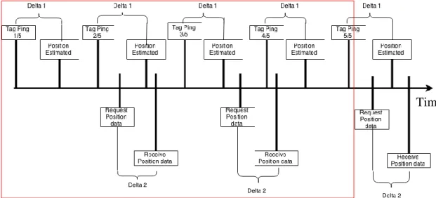
As explained above and shown in Figure 15, Locantis is based on a centralised IPS to collect position data and a smart device that acts recipient in a semi-distributed system. Adding more technology and changing the purpose of the system to the one of Locantis creates a new timeline of events. When Locantis is active and running four major events, tag ping, position estimated, request and retrieve position data, are taking place. An example of this can be seen in Figure 16, where the duration of little more than one second is illustrated. The red square marks the events that would be taking place within the duration of one second. Here, the tag is configured to ping its location with 5 Hz and Locantis app is requesting positioning data at 2Hz.
Figure 16: Locantis timeline of events.
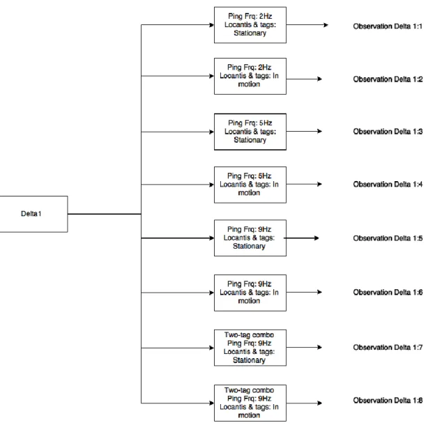
The experimental investigation determines the performance of Locantis by examining how the system is reacting to controlled changes made within the system. In chapter 3.1, the terminology for the experimental investigation is stated and explained. Delta 1 & 2, as can be seen in Figure 16, are under investigation and described in more detail in 4.2.3 and 4.2.3, where the experiments are stated and explained.
4.1.2 Embedded sensors
In chapter 2.5 a number of sensors are listed and two are stated as interesting for this thesis and implementation into Locantis. In this thesis the smartphone running Locantis application is not embedded in any other equipment and is a standalone device. To prove the concept of data combination of the embedded sensor data combined with positioning data, all data is displayed on the
smartphones display. In the future, this data would be used as discussed in chapter 2.5.
The geomagnetic sensors application-programming interface (API) is used as a compass to display the heading of exercise participants. The heading and compass data are displayed as shown Figure 17 below. Here it is seen that the current heading is 26° to east-northeast.
Figure 17: Compass and heading representation in Locantis app.
The accelerometer data is collected using the accelerometer API. The
accelerometer gives values for acceleration forces on the device in relation to X, Y and Z reference planes. The values are represented as numerical values. In Figure 18, below, the acceleration data representation can be seen. These values are from a device that has undergone heavy shaking and then positioned flat on the back on top of a table. The first three rows are the current acceleration forces on the device and the later three rows are maximum-recorded acceleration forces on the device. It should be noted that 0.0 means that there is no change in force on the device. In reality, objects at rest are under the force of 1.0 G in reference to the Z plane.
4.1.3 Communication
In order for the smartphone with the developed application to be able to receive the centrally collected positioning data the application must have some means of communication. Having a smartphone as a platform for simulation equipment has some benefits regarding the communication. Smartphones today have several means of radio communication, such as GSM, 3G, 4G, BT and Wi-Fi, that could be used for this purpose. In this project, Wi-Fi is considered to be the most sufficient and suitable mean of communication for distribution of the positioning data. Wi-Fi requires access points the smartphone can connect to. In this project, the experimental procedure is taking place in a room small enough for only one access point to be required in order to be able to conduct the investigation. Measuring the receiver signal strength indicator (RSSI) value of the single Wi-Fi access point in this investigation ensures that this is the case.
Locantis app receives positioning data by sending HTTP requests to a uniform resource locator (URL) that is unique for the tag that is being tracked. This way of distribution provides posibility to request positioning data from a single tag. There are other ways that the positioning data could be distributed. For instance, user datagram protocol (UDP). This way the NCHAIP system broadcasts the positioning data on a designate internet protocol address (IP address) and the receiving device are listening for broadcasts on that specific IP address. HTTP requests are selected as the way for Locantis app to receive positioning data since the implementation is fairly straight forward and HTTP requests can provide high enough update frequency.
4.2 Experimental research
In this chapter the experimental investigation is discussed. The experiments are explained and the different components used are stated.
4.2.1 Experimental set up
The experiments designed for this thesis are conducted in what will be an office landscape, but for now is empty. The testing and experiment area is some 130 𝑚2 with concrete walls and roof pillars. The IPS used in the experiments is a
NCHAIP system from Quuppa. The system consists of five HAIP locators, a power over Ethernet (POE) switch that connects the HAIP locators and a HAIP controller in a wired network, and 15 HAIP tags included in the demo kit. Figure 19 shows how the different components of HAIP system are connected to each other.
![Figure 1: The 2.4 GHz ISM band is clustered with wireless transmissions from several technologies [12]](https://thumb-eu.123doks.com/thumbv2/5dokorg/5452263.141318/18.892.138.757.552.721/figure-ghz-ism-band-clustered-wireless-transmissions-technologies.webp)
![Figure 4: BLE advertising and data channels. 37, 38 and 39 are advertising channels [12]](https://thumb-eu.123doks.com/thumbv2/5dokorg/5452263.141318/23.892.142.752.346.652/figure-ble-advertising-data-channels-advertising-channels.webp)
![Figure 8: Positioning principle with two HAIP Locators [2].](https://thumb-eu.123doks.com/thumbv2/5dokorg/5452263.141318/27.892.226.661.774.1060/figure-positioning-principle-haip-locators.webp)