1876-6102 © 2017 The Authors. Published by Elsevier Ltd. This is an open access article under the CC BY-NC-ND license (http://creativecommons.org/licenses/by-nc-nd/4.0/).
Peer-review under responsibility of the scientific committee of the 8th International Conference on Applied Energy. doi: 10.1016/j.egypro.2017.03.932
Energy Procedia 105 ( 2017 ) 4389 – 4394
ScienceDirect
The 8
thInternational Conference on Applied Energy – ICAE2016
Numerical Evaluation on a Direct-contact Thermal Energy
Storage system
Weilong Wanga, Shiquan Heb,*,Jing Dinga, Hailong Lic, Jinyue Yanc, Jianping Yangd aSchool of Engineering, Sun Yat-sen University, Guangzhou, China bAcademy of Building Energy Efficiency of Guangzhou University, Guangzhou, China
cSchool of Business, Society and Energy, Mälardalen University, Västerås, Sweden
d School of Chemistry and Chemical Engineering, South China University of Technology, Guangzhou, China
Abstract
This study evaluates numerically various configurations of direct-contact PCM thermal energy storage devices, regarding inlet location, inlet flow directions, pre-heating and inlet tubes with straight fins. The direct-contact conjugate heat transfer between the heat transfer fluid (HTF) and PCM during melting process, is solved numerically by enthalpy-porosity formulation in the computational fluid dynamic approach . The results indicate that pre-heating could form channels in a short time, which improve heat transfer rate for charging stages. To further enhance heat transfer performance, inlet tubes embedded with straight fins. Compared to pre-heating method, the electric power can be saved. Each design are evaluated with respect to their heat transfer performance vis-à-vis heat storage ratio.
© 2016 The Authors. Published by Elsevier Ltd.
Selection and/or peer-review under responsibility of ICAE
Keywords: Quick channel, Fins, Heat transfer performance, Numerical simulation, Direct-Contact thermal energy storage
1. Introduction
Thermal storage system with phase change material is widely used in industrial waste heat recovery. The waste heat melts the PCM and is stored in the form of latent heat. Compared with the indirect heat exchange system, the direct-contact system has an extremely simple structure and more rapid heat exchange due to the negligible pipe or capsule[1,2]. Recently, some work studied the performance of direct-contact energy storage system, and found that shortening the charging time could improve the technical and economic performances[3-5]. Therefore, this paper is to investigate the heat storage performance and phase change behavior of PCM in the direct-contact structure of energy storage system through numerical simulation. Six cases are proposed and then calculated to find out the key factor on © 2017 The Authors. Published by Elsevier Ltd. This is an open access article under the CC BY-NC-ND license
(http://creativecommons.org/licenses/by-nc-nd/4.0/).
decreasing charging time. The results will provide guidelines for the design and optimization of the direct contact energy storage system.
2. Simulation model and numerics
A two-dimensional CFD model using ANSYS FLUENT code was built to analyze the melting behavior of the PCM. According to experimental results, the model has been simplified by ignoring the melting behavior difference in the axial direction. The PCM below the inlets on the bottom was neglected due to the negligible thermal energy stored in that small quantity and the inlet pipes were replaced by two edges. The residual of all variables was 10-3. The time step for integrating temporal derivatives was 0.1 s. The model has been validated in our previous work[5], and it showed a good agreement with experiment.
The properties of thermal oil are fixed at temperature 140 ć , and the properties of PCM are temperature dependent. The melting point of PCM is 120 ć. All the thermal physical properties are presented in reference [6].
At the beginning of calculation, the temperature of oil and PCM was set as ambient temperature and the liquid fraction was zero. The inlet boundary was given temperature and mass flow rate of thermal oil. The boundary was pressure outlet.
In our previous study, the melting process was divided into two stages, forming channels and melting solid, as illustrated in Fig. 1. The first stage, forming channels, spent quite a long time to finish, and the heat release efficiency was low. The second stage had a high efficiency and spent less time. Therefore, shortening the time of forming channels could improve the efficiency of melting stage.
Fig. 1 The stages of melting process
Seven cases were proposed with various designed structure in our calculation to find out the way of improving melting process, as illustrated in Table 1. Case 1 was experimental measured, and the inlet flow direction was upward. Case 2 and Case 3 had the inlets on the interface between oil and PCM region. Both cases would not form channels during the melting process. The inlet flow direction of case 2 was upward. In case 3, the directions were opposite, and flow disturbance in oil region would much stronger than that in case 2. To accelerate formation of channels, heaters were set up in case 4 and 5, but the electric power was different. Case 6 was designed using another way to form channels. Thermal oil flowed downward in the inlet tubes with straight fins. Prior to the formation of channels, heat transfer between hot oil and solid PCM is heat conduction, and the straight fins could enhance heat transfer and reduce the time of forming channels. In case 7, heat flux was added to the fins and tube surfaces. When the solid PCM around fins became liquid and flow channels formed, thermal oil began to flow and the heat flux was set to zero. All the cases have the same inlet flow rate, 0.1h2 kg/s, and the thermal oil temperature is 140 ć. The initial temperature of PCM and oil is 25 ć.
Table 1 Case List (Foil=0.2 kg·s-1, Tin=140 ć)
Case Number Sketch Pre-heating power Case Number Sketch Pre-heating power Stage 1:
Forming channel
Stage 2: Melting stage
1 50% 50% Thermal Oil PCM Inlet Inlet Outlet Stage 1: q1=0 W Stage 2: q1=0 W - 5 50% 50% Thermal Oil PCM Inlet Inlet Outlet q2 q2 Stage 1: q2=1000 W Stage 2: q2=0 W 2 50% 50% Thermal Oil PCM Inlet Inlet Outlet Stage 1: q1=0 W Stage 2: q1=0 W 6 50% 50% Thermal Oil PCM Inlet Inlet Outlet Stage 1: q1=0 W Stage 2: q1=0 W 3 50% 50% Thermal Oil PCM Inlet Inlet Outlet Stage 1: q1=100 W Stage 2: q1=0 W 7 50% 50% Thermal Oil PCM Inlet Inlet Outlet q3 q3 Stage 1: q3=50 W Stage 2:q3=0 W 4 50% 50% Thermal Oil PCM Inlet Inlet Outlet q1 q1 Stage 1: q1=100 W Stage 2: q1=0 W
3. Results and discussion 3.1. Flow dynamical performance
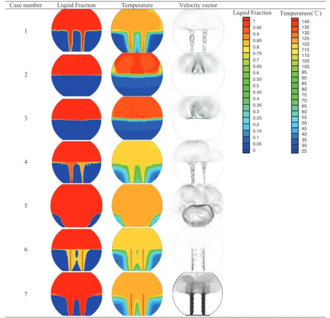
The time evolution of melting of PCM is presented in table 2. Solid PCM is blue and liquid region is red. In case 1, surface contact area between oil and PCM is enlarged when channels form, and the melting process is accelerated. However, although case 2 and case 3 can save the time of forming channels, they offer worse heat transfer performance, since melting fraction at the initial stage of melting process are smaller, and heat transfer region is limited to the interface with constant contact area.
Although case 1 shows a good characteristic of melting process, it takes a long time to form channels. To shorten the time of forming channels, two heaters are installed in each channel region. Power of each heater is 100 W and 1000 W corresponding to case 4 and case 5, respectively. When the channels form, heaters are powered off. Results show that case 4 and 5 dramatically cut off the melting time due to the quick channels forming. The melting process could be further accelerated with higher power, since the channel forming time is much shorter.
It should be noticed that when the heating power is too high in case 4 and 5, the liquid around heaters will be overheated, and lead to dissociation of PCM and oil. Furthermore, electric energy consumption should be considered. Therefore, two inlet tubes with straight fins on the outside surface are designed to form quick channels with less electric energy consumption. In case 6, thermal oil flowed downward in the inlet tubes. Due to the large surface contact area, solid PCM around fins could melt in a short time. After that, heat transfer around tube fins is mainly convection and it is enhanced through the fins. In case 7, the flow dynamical performance is similar to that in case 6, but the temperature is a little higher due to the additional preheated power.
In the two channels, liquid PCM is disturbed by thermal oil, and it has a high velocity magnitude. When the solid PCM between two channels disappear, turbulence intensity inside PCM region becomes strong, and convection heat transfer is enhanced. In case 6 and case 7, we can see natural convection heat
transfer represented by high velocity magnitude around the fins, especially in the region between two tubes.
Table 2 Liquid fraction of PCM, temperature and velocity vector during charging at 100 minutes Case number Liquid Fraction Temperature Velocity vector
1 Liquid Fraction 1 0.95 0.9 0.85 0.8 0.75 0.7 0.65 0.6 0.55 0.5 0.45 0.4 0.35 0.3 0.25 0.2 0.15 0.1 0.05 0 Temperature(ć) 140 135 130 125 120 115 110 105 100 95 90 85 80 75 70 65 60 55 50 45 40 35 30 25 2 3 4 5 6 7
Fig. 2 presents the liquid fraction of the calculated cases during melting process. Here, several features are apparent: foremost among them is that cases with pre-heaters (case 4, case 5) yield higher heat transfer rate as compared to case without pre-heaters (case 1). It is also noted that cases with inlets located at the top of PCM region (case 2, case 3) perform lower heat transfer rate as compared to case with inlets located at the bottom (case 1). Charging rate for case 5 improves by up to around ~56% followed by case 4 (~11%) compared to case 1. Simultaneously, it is found that case 1 and case 4 offer low heat transfer rate in the first 50 minutes, and which is due to the fact that heat transfer is mainly conduction in the first stage, forming channels. After 50 minutes, the first stage has finished, and thermal oil could flow through
the channels. Convection heat transfer is dominated and liquid PCM could be disturbed by the flow, and thus the melting rate increases significantly. However, the first stage is not so clear in case 5, case 6 and case 7. Due to high electric power in case 5, the forming channels stage is finished in a short time. In case 6 and case 7, natural convection and conduction coexist simultaneously around fins, and hence heat transfer is significant enhanced. Consequently, melting rate will be kept in a high value. In reference [3], wall heating case is studied to improve the heat transfer close to the container corners, but the result shows the melting time has no change in the first 60 minutes.
0 100 200 300 400 0.0 0.2 0.4 0.6 0.8 1.0 Time/mins Liquid Fraction of PCM Case 1 Case 2 Case 3 Case 4 Case 5 Case 6 Case 7 Wall heating[3]
Fig. 2 Liquid fraction of charging phase change material
3.2. Energy storage efficiency
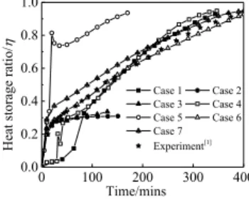
Fig. 3 shows the heat storage ratio in the heat storage process. Heat storage rate for case 5 is higher than other cases. It took about 170 minutes to finish 97% heat storage, while the time for case 4, case 5, case 6 and case 7 is over 300 minutes. Heat storage ratio for case 2 and case 3 is only 30% at 150 minutes, and the curves become flat after 20 minutes. The rapid heat storage ratio rise in the first 20 minutes is caused by the increase of sensible heat storage of thermal oil. From 20 to 150 minutes, the contact surface area is limited on the top of solid PCM, and heat transfer is mainly conduction. This results in a low melting rate. In case 1 and case 4, heat storage ratio is quite low before 50 minutes. According to table 2, liquid fraction also shows a small increase since the process is the forming channels stage. Subsequently, the storage rate increase as the increase of time when the channels have formed. However, a decrease is observed at 32 and 20 minute corresponding to case 4 and case 5, respectively. At this point, heaters were powered off and thermal oil began to flow. The liquid temperature around heaters is higher than thermal oil, therefore, heat storage ration shows a decrease. Although heat storage for case 5 is much higher, temperature on the surface of heaters also reach a high value, and the PCM could be over heated and dissociated. As can be seen in Fig. 2, heat storage rate for case 6 and case 7 shows a high value at the beginning, and the PCM will not be at the risk of overheating. In case 7, heat storage ratio is higher than the value in case 6 before 100 minutes because of the preheated heat flux.
0 100 200 300 400 0.0 0.2 0.4 0.6 0.8 1.0 Time/mins
Heat storage ratio/
K Case 1 Case 2 Case 3 Case 4 Case 5 Case 6 Case 7 Experiment[1]
Fig. 3 Heat storage ratio of charging phase change material
In the present work, a numerical investigation is carried out to investigate and enhance the heat transfer performance in the direct-contact thermal energy storage system (TES), viz. inlet modification and formation of quick channels. The results indicate that the design with quick formed channels provides higher heat transfer performance followed by inlet modification. It is found that the time of forming channels could be shorten as the increase of pre-heating power.
It is also found that the implementation of inlet tubes with straight fins could enhance heat transfer performance within the direct-contact TES. Straight fins significantly enhance the heat transfer performance due to the large surface contact area and natural convection. Inlet tubes with straight fins during charging process forms channels in a short time, and it helps to shorten the time of charging process.
5. Copyright
Authors keep full copyright over papers published in Energy Procedia.
Acknowledgements
This paper was financial supported by Natural Science Foundation of Guangdong Province (2014A030310377), Nature Science Foundation of China (U1507113), High School Science & Technology Fund Planning Project of Guangzhou (1201431060), Science and Technology Planning
Project of Guangdong Province (2015A010106006) and "Yangcheng Scholar" Project of Guangzhou
(1201581559).
References
[1] Akihide K, Hiroomi K, Atsushi K, et al. Thermal and flow behaviors in heat transportation container using phase change material. Energy Convers Manage 2008;49:698-706.
[2]Nomura T, Tsubota M, Sagara A, et al. Performance analysis of hea storage of direct-contact heat exhanger with phase-change material. Appl Therm Eng 2013;58:108-113.
[3]Shaopeng G, Hailong L, Jun Zh, et al. Numerical simulation study on optimizing charging process of the direct contact mobilized thermal energy storage. Appl Energy 2013;112:1416-1423.
[4] Weilong W, Hailong L, Shaopeng G, et al. Numerical simulation study on discharging process of the direct-contact phase change energy storage system. Appl Energy 2015;150:61-68.
[5] Weilong W, Shaopeng G, Hailong L, et al. Experimental Study on the Direct/indirect Contact Energy Storage Container in Mobilized Thermal Energy System (M-TES). Appl Energy 2014;119:181-9.
[6] Weilong W, Shiquan H, Shaopeng G, et al. A combined experimental and simulation study on charging process of Erythritol-HTO direct-blending based energy storage system. Energy Convers Manage 2014;83:306-313.
Biography
Weilong Wang, working at the Sun Yat-sen University, focuses on heat and mass transfer, energy storage, heat transfer enhancement, sustainable and renewable energy.