Adapting offshore
wind power foundations
to local environment
report 6367 • may 2010
Conditions for marine life are affected on sites where new materials and surfaces are introduced to the bottom of the ocean.
The offshore wind mill foundations are all made of hard structures but the effects on the marine life varies depending on the surface conditions of the foundation and the methods of installation. Another factor of impact is the type of habitat existing before establishment.
This report describes the various types of changes in the marine habitat which can be expected during establishment of offshore wind mill foundations on different types of bottom substrates.
The knowledge can be used as a basis for planning, licensing and environmental impact assessments concer-ning offshore wind parks.
issn 0282-7298
wind power foundations
to local environment
Vindval is a programme that collects knowledge on the environmental
impact of wind power on the environment, the social landscape and people’s perception of it. It is aiming to facilitate the development of wind power in Sweden by improving knowledge used in IEAs and planning- and permission processes. Vindval finances research projects, analyses, syntheses and dissemination activities. The programe has a steering group with representatives for central and regional authorities and the wind power industry.
SWEDISH ENVIRONMENTAL PROTECTION AGENCY
by Linus Hammar, Sandra Andersson and Rutger Rosenberg Translation: Anna Dimming
Internet: www.naturvardsverket.se/bokhandeln The Swedish Environmental Protection Agency Phone: + 46 (0)8-698 10 00, Fax: + 46 (0)8-20 29 25
E-mail: registrator@naturvardsverket.se
Address: Naturvårdsverket, SE-106 48 Stockholm, Sweden Internet: www.naturvardsverket.se
ISBN 978-91-620-6367-2.pdf ISSN 0282-7298
Preface
There is a great need for knowledge concerning the impact of wind power on humans and landscapes, the marine environment, birds, bats and other mam mals. Previous studies regarding the environmental impacts from wind farms have lacked an overall view of the effects. This has lead to deficiencies in the processes of establishing new wind farms.
Vindval is a program of knowledge and a cooperation between Energi myndigheten (Energy Authority) and Naturvårdsverket (Environmental Protection Agency). The purpose of the program is to collect and distribute scientific based facts regarding the impacts of wind power on human and nature. The commission of Vindval extends to 2012.
The program comprises about 30 individual projects and also three so called works of syntheses. These syntheses consists of experts which compile and assess the collected results of research and experience regarding the effects of wind power within three different areas – humans, birds/bats and marine life. The results from the research projects and work of syntheses will provide a basis for environmental impact assessments and in the processes of planning and permitting associated with wind power establishments.
Vindval requires high standard in the work of reviewing and decision making regarding research applications in order to guarantee high quality reports. These high standard works are also carried out during the reporting approval and publication of research results in the projects.
This report was written by Marine Monitoring AB; Linus Hammar, Sandra Andersson and Rutger Rosenberg 2007 and translated by Anna Dimming 2010. The authors are responsible for the content.
Contents
PrEfAcE 3 SummAry 7 1 InTrOducTIOn 9 2 fOundATIOnS 12 2.1 Gravity foundation 132.1.1 General information on gravity foundation 13 2.1.2 When is a gravity foundation used? 13 2.1.3 A detailed description of concrete gravity foundation 14 2.1.4 Description of steel gravity foundations 15 2.1.5 Construction of gravity foundation 15 2.1.6 Applied summary of gravity foundation 16
2.2 Monopile foundation 17
2.2.1 General information on monopile foundation 17 2.2.2 When is a monopile foundation used? 18 2.2.3 A detailed description of monopile foundation 18 2.2.4 Construction of monopile foundation 19 2.2.5 Applied summary of monopile foundation 20
2.3 Tripod foundation 21
2.3.1 General information of tripod foundation 21 2.3.2 When is a tripod foundation used? 22 2.3.3 Applied summary of tripod foundation 22
2.4 Jacket foundation 23
2.4.1 General information of jacket foundation 24 2.4.2 When is a jacket foundation used? 24 2.4.3 Applied summary of jacket foundation 25
2.5 Other foundations 25
2.6 Score protection 27
3 SOurcES Of InfluEncES 29
3.1 Fouling and reef-effect 30
3.1.1 Background 30
3.1.2 Differences between sea areas 34
3.1.3 Differences between various foundations 35 3.1.4 Adjustments to minimize or maximize the impact 37 3.2 Noise during the operational stage 41
3.2.1 Background 41
3.2.2 Differences between ocean areas 45 3.2.3 Differences between the various foundations 46 3.2.4 Adjustments in order to reduce negative impacts 47
3.3.2 Differences between ocean areas 51 3.3.3 Differences between the various foundations 52 3.3.4 Adjustments to reduce the negative impacts 53
3.4 Construction noise 53
3.4.1 Background 53
3.4.2 Differences between ocean areas 58 3.4.3 Differences between the various foundations 58 3.4.4 Adjustments to reduce the negative impacts 58 3.5 The spread of sediment during the construction phase 61
3.5.1 Background 61
3.5.2 Immediate effects of construction work at Lillgrund wind park 62 3.5.3 Differences between ocean areas 63 3.5.4 Differences between various foundations 64 3.5.5 Adjustments to minimize negative impacts 64
4 fOundATIOn OPTImIzATIOn 65
4.1 Summary – Gravity foundation 65
4.2 Summary – Monopile foundation 66
4.3 Summary – Tripod foundation 67
4.4 Summary – Jacket foundation 69
4.5 Summary – Other foundations 70
4.6 Other sources of impact 70
4.7 A relative degree of influence on the environmental impact 70 4.8 Recommendations in the choice of foundation 72
rEfErEncES 77
Personal communication 85
Summary
The aim of this study is to provide an environmental perspective regarding the choice of foundations for offshore windpower, suggesting that differences in environmental impact should be involved in decisionmaking and develop ment concerning future offshore windpower foundations. The study concerns only the marine environment, excluding seabirds, and is based on the level of knowledge available in 2007.
The study focuses on three different types of foundations; gravity mono pile and jacket foundations. Also tripod bucket and floating foundations are mentioned. The different characteristics of the foundations are discussed based on their environmental impact in five different areas; 1) epifouling and reefeffects, 2) operational noise, 3) changes in hydrographical conditions, 4) noise during construction, and 5) dissolved sediment during construction.
Regarding epifouling, it is noted that the surface texture of the founda tion (i.e. steel, concrete) is of less importance in the long run since the initial substrate soon will be covered with organisms, creating a rugged surface for later colonising organisms. It is rather the level of salinity, distance to shore, exposure, depth and turbidity of the water that decide which organisms that will dominate the different foundations after a few years. Generally all foun dations for offshore windpower are expected to be dominated by filtering ani mals, such as blue mussels. A possible exception is if concrete is coated with a silicone product that limits larger organisms to establish on the foundations. This kind of surface treatment has not yet been used by the windpower indus try but occurs on other submarine concrete constructions.
The potential for an evident reefeffect (local increased occurrence of mobile animals such as fish and crustaceans) increases with the complexity of the foun dation structure. Hence, tripod and especially jacket foundations have better pos sibility to contribute to the reefeffect than monopile and gravity foundations.
Reefeffect, as well as epifouling, may be considered negative in some marine environments, such as possible valuable areas without any natural occurrence of hard substratum. In such areas new species may be introduced, changing the local ecological conditions. However, in many areas an increased level of biological diversity is viewed as a positive change, and here reefeffect and epifouling may be considered favourable. To amplify the reefeffect, scour protection devices may be designed to create more habitats.
Operational noise from offshore windfarms has been shown to initially affect some organisms (mussels, fish) during experimental studies in small containers. Whether corresponding operational noise in field and during natural circumstances can cause any environmental impacts is not yet fully understood. Available information indicates that there is a common sound level peak from wind turbines at frequencies of 100 – 200 Hz. In the same frequency range cargo ships emit higher sound than wind power even over several kilometres distance. Based on the present lack of certainty, it can be motivated to minimize the sound at these frequencies in areas with special
biological values, such as endangered organisms sensitive to stress. However, there are no indications that operational noise may significantly affect the environment beyond the vicinity of each foundation.
Based on a limited number of measurements it seems as if gravity and monopile foundations emit noise of similar amplitude, but the frequency range of the gravity foundation is generally lower. There are no measurements of jacket foundation but theoretically these should emit less noise, at least within the lower frequency range. Even if little is known about future turbines and foundations, it should be technically possible to decrease the emitted noise level.
The local conditions of the seabed have a large impact on the propaga tion of the noise, where shallow water and hard substratum allow the sound to propagate longer distances. The background noise is also of importance and in quiet areas there is theoretically a higher risk of environmental impacts than in areas with heavy ship traffic.
Changes in the hydrographical conditions around a foundation are small and are expected to be of importance only in very narrow water passages. The gravity foundation probably has the largest impact on the local hydrography. However, no direct comparisons between the different foundations have been made.
During the construction period extreme noise levels may occur, especially during piledriving which is needed for most foundations except for grav ity foundations. The noise level depends on the diameter of the piles that are driven into the sediment as well as the piling method. This means that the monopile foundation generally emits higher construction noise levels than jackets, while gravity foundations emit the least construction noise.
Since the extreme noise levels from piledriving, covering large areas, can be harmful to fish and marine mammals it is very important to minimize this disturbance. This can be done by the choice of foundation, by precautionary measures and by adapted methods of piledriving. It is of great importance not to perform piledriving during spawning periods of commercially valuable fish species.
Gravity foundations need no piledriving but require dredging, which dis perses dissolved sediment in the water. High concentration of dispersed sedi ment can disturb or harm sensitive marine organisms such as juvenile fish. The highest risk of negative impact on the environment is dredging calcareous sediments, dredging in stagnant water and where the sediment contains toxic substances. The impact on the environment from dredging can be minimized by precautionary measures and good planning. However, the impact of dredg ing and sediment transport related to offshore windpower is small compared to other large dredging projects that have been carried out in Sweden without any documented any sustained environmental impacts.
1 Introduction
A major expansion of offshore wind power in northern Europe is to be expected in the near future. Today (2007) there are 25 offshore wind farms in operation, while more than 30 wind farms are planned of have permission to get started, see Table 1.
The projections of offshore wind power normally involve extensive envi ronmental screening, which includes the anticipated effects on marine algae and animals. The environmental impact statements analysed in Swedish pro jections are often considering the marine environment thoroughly, but has not in detail dealt with wind mill foundations. There are major technical dif ferences between foundations and the different models have their particular advantages depending on prevailing environmental conditions. There are also substantial differences of the environmental impacts from the various founda tions, which is not clearly analyzed in environmental trials.
The choice of foundation has been made only after authorization and is mainly due to the required geotechnical investigation of the bottom which is costly. There is also an advantage taking a late decision regarding the rapid evolution of technology. So far the choice and design of the foundations have been exclusively based on technical and economical aspects. The purpose of this study is that marine biological and ecological aspects of the foundation are to be taken into consideration in the early stages of planning thereby increasing precision of future environmental impact assessments and the pro motion of an optimized planning of offshore wind mills.
This study intends to compare the fundamental works in relation to envi ronmental impacts (such as reefeffects, sound, changes in hydrographical conditions)regardless if this influence then presents a significant environmen tal impact or not.
Reading instructions
This study of foundation optimization is especially addressed to wind energy developers working with environmental impact assessment and planning, as well as to administrators and policy makers involved in the authorization process. Chapter 2 provides a technical overview of the various foundation models, and Chapter 3 deals with the different foundations in relation to envi ronmental impacts. In Chapter 4, the results are summarised with suggestions how to use them. It is very important that this study is to be considered in its entirety for use, and not where Chapter 4 or Table 6 is used without knowl edge of the other content. Conclusions concerning the foundations carrying a more or less environmental impact should be interpreted from the knowledge that this whole “moreorless scale” in some cases may be within what is con sidered a moderate environmental impact.
The study does not intent to represent the whole state of knowledge regard ing the potential environmental impacts (Chapter 3) and the study is based on current (2007) technologies and applications. Information and recommendations should therefore be corrected in line with increased knowledge and technological
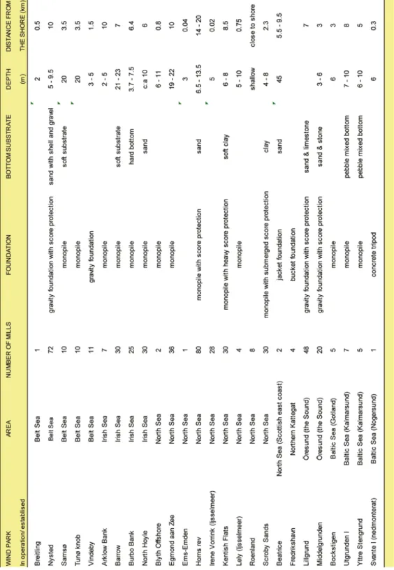
Table 1b. A list containing some of the offshore wind parks being planned, permitted or under construction in northern Europe (2007).
2 Foundations
This chapter provides a description of various foundations used in order to anchor offshore wind mills. The models described includes; gravity, monopile, jacket, tripod, bucket and floating foundations. A feedback to the ecological impact is given in Chapter 3.
The descriptions are based on information from experts in the offshore industry as well as technical evaluations, detailed descriptions and design manuals. Specific technical information has been obtained from Vattenfall and E.on especially concerning the most common foundation models in the current situation; gravity and monopile foundation. Dimensions and other details should only be considered as examples; since the design and dimen sions of the foundations vary from case to case due to the current circum stances. The future foundations can be expected to be generally larger than the foundations used today (2007) due to the trend towards higher installed capacity (MW).
Section 2.6 provides a general description of score protection which is used especially for gravity foundation but in some cases also for other foundation models. Facts about anodes, which are used in connection with cathode protec tion, can be found in information box 1.
Information box 1. cathode protection of anodes
Anodes with cathode protection are commonly used to prevent oxidation and corrosion of metals. The anodes are consisting of metal rods attached to the outside of the foun-dations, where it is in contact with the metallic parts of the foundation to be protected (for example; pile and transition piece on monopile foundations or reinforcement bar on concrete gravity foundations). The anodes used in Lillgrund wind park (gravity founda-tions) consist of 1.5 m long pieces of 64 kg anodic metal compound, containing mainly of zinc (Zn), and a small part of indium (In), copper (Cu), cadmium (Cd), silicon (Si), iron (Fe) and aluminum (Al) (Grahn personal comment).
Anodes are consumed and replaced within a 10 year time interval. Several of the active substances are toxic, but the emissions are relatively small per unit time. Cathode preventive anodes are not specific to wind power foundations but are used widely in the protection of steel structures in marine environments.
definitions
SGS Societe Generale de Surveillance SA DWIA Danish Wind Energy Association WPD Wind Power Development
EWEA European Wind Energy Association OES Offshore Environmental Solutions
2.1 Gravity foundation
Figure 1. A schematic outline of a concrete gravity foundation. The scale is not proportional; for details and dimensions see section 2.1.3.
2.1.1 General information on gravity foundation
As the name indicates, a gravity foundation works by using its weight to keep the wind turbine in an upright position. A base consisting of a concrete caisson or a steel container is plunged into the bottom where it is filled up to and above the level of the surrounding seabed with ballast stones, concrete or other mate rial of high density. Almost always, the gravity foundations require some kind of score control to prevent the water movement in undermining the anchorage. The foundation has a time glass design to prevent ice damage during cold win ters which allows the upper angle to break ice away.
2.1.2 When is a gravity foundation used?
The concrete gravity foundations have a relatively large base resulting in a high load from water movements laterally, and the cost for traditional gravity founda tions (manufacturing and installation) increase exponentially with depth. There fore, the concrete gravity foundations (Fig.1) are mainly an option for shallow water. From an economic point of view, up to date (2007) tested versions of the concrete gravity foundations are suitable down to about 10m (DWIA 2003;
are prototypes designed for depths of 2030m, which is planned for a Belgian wind power project in the Thornton Bank of North Sea (EWEA 2007). Gravity foundations made of steel have been developed to be able to utilize deeper water with this kind of foundation (Fig 2; see section 2.1.3) (DWIA 2003).
Gravity foundations can be adapted to a variety of bottom substrates by adjusting the base diameter because this kind of foundation does not require a deeper recess in the bottom substrate. This implies that gravity foundations are well suited for rocky bottoms and bottoms with boulders as well as stable (well packed) sediments. Bottoms of consistently loose sediment are on the contrary not appropriate for the gravity foundations (SGS 2005).
The gravity foundations are used for example at the wind parks of Nysted (Bälthavet), Middelgrunden (Öresund), Vindeby (Bälthavet), TunØ Knob (Bälthavet) och Lillgrund (Öresund).
2.1.3 A detailed description of concrete gravity foundation
Depending on the water depth, exposure (waves and currents), drifting ice and the size of the tower, there is a variation in the proportions of every individual grav-ity foundation. The foundations at the wind parks of Middelgrund and Lillgrund are standing on bottoms with an interval of 4 - 9m in depth in the Öresund with rather strong currents. They have concrete caissons with a diameter of 16.7 – 17.6 respectively 16.5 – 19.0 meter (Grahn personel comment; Sorensen et al 2002). At the Middelgrund, the weight of the foundations is 1 800 tons including the ballast (Sorensen et al 2002). The ballast used with the gravity foundations may consist of sand, stones, concrete or iron ore (SGS 2005).
At Lillgrund, the hexagonal caisson of concrete is immersed 2.5 m and protrudes 0.6 m up from the bottom. The caisson is resting on a bed of stones and is filled with an underlying layer of gravel (Ø = 35 – 350 mm) and an overlay of larger boulders (200 – 1 200 kg per stone). From the caisson, the foundation rises up through an approximately 5m diameter concrete column filled with ballast, which extend conical (55⁰ angle) towards the surface to a platform of 10 m in diameter. The reinforced concrete is smooth (cast in steel / wooden molds) and not painted.
To avoid corrosion, zinc anodes are mainly used since leading metals delay corrosion of reinforcement inside the concrete. Anodes are consumed and replaced within a 10 year time interval (Grahn personal comment).
At the Lillgrund wind park, the score protection extends 6 – 8 m around the recessed concrete caisson, which leads to a total diameter of 35 m. The score protection outermost consists of gravel (Ø = 35 – 350 mm) and further into the pillar boulders are used (30 – 350 kg per stone) (Grahn personal comment).
2.1.4 description of steel gravity foundations
An alternative to concrete gravity foundations with caisson is gravity foun dation with a smaller and lighter base consisting of a steel container. The steel container, which is in the magnitude of Ø = 15 m for a water depth of 4 – 10 m, is filled with high density materials such as “olivine” (magnesium ironsilicate) (DWIA 2003). The foundation is built on a preprocessed bed of gravel and is generally in need of score protection.
The great advantages with the steel gravity foundation, in comparison with the concrete foundation, are the lighter handling weight and also that the production and installation expenses do not increase exponentially with depth (DWIA 2003). At greater depths, where the expenses for installation usually are high, the steel foundation may be favorable.
2.1.5 construction of gravity foundation
In the construction of gravity foundation the bottom is preprocessed in several stages; 1) dredging, 2) paving 3) attachment of the foundation, and 4) the fill ing of ballast.
The work of dredging from dredging vessels results in a recess in the sea bottom of specific measures. Where larger boulders are present, these are blasted into pieces. In those cases, a smaller explosive charge is set before, in
Figure 2. A schematic outline of a steel gravity foundation. The scale is not proportional; for details and dimensions see section 2.1.4.
Lillgrund, the dredging was performed from vessels and was accomplished in two separate steps – rough dredging down to 0.5 m over the calculated depth and then a more precise dredging (Peter Madsen Shipping 2006). The sedi ment dredged and removed from Lillgrund was about 1 500 – 2 000 ton per foundation, with a spread distribution of various amount of days depending on local bottom conditions and weather. The dredged material was deposited on land.
After completed dredging there is a bed of crushed stones established for the foundation to rest upon. The stones are spread over the dredged area by a bar, maneuverable from a vessel, which results in a flatbed of stones. In Lillgrund Wind Park this bed of stones was 0.3 m thick, containing about 130 m3 of crushed stones for every foundation.
When the bed of stones is completed, the gravity foundation is placed by a vessel with a crane after which the ballast is filled (see section 2.1.2). The most sensitive parts of the foundation can be protected with wooden boards during the ballast filling (Grahn personal comment).
During the whole work of installation, the ship is fixed in position with spud legs, computerized operated propellers or computerized anchor ropes. Inspection with divers is made after every completed section.
2.1.6 Applied summary of gravity foundation
Gravity foundations require a greater bottom area than other foundations. The natural bottom is destroyed and replaced by an artificial substrate which gives new conditions for marine organisms. During the work of installation there is sediment spreading activity which may cause local effects. The list below is a summary of relevant biological impacts related to installation of gravity foundations. The information is mainly based on the conditions at Lillgrund. The details from Lillgrund are to be considered of general interest since the wind parks of both Nysted and Middelgrund have nearly identical foundations.
Structure (for every foundation)
• Foundation pillars: creates an artificial vertical bottom surface of smooth concrete
• Conical platform: creates an artificial overhang
• Eventual caisson of concrete: creates an artificial horizontal bottom surface (about 250 m2) of stones, elevated 0.5 – 1 m above the bottom
• Container of steel: creates an artificial bottom surface of surface-treated steel, could be covered by horizontal score protection (stones)
• Score protection: creates an artificial horizontal bottom surface (about 650 m2) of stones and gravel
Work of construction (for every foundation)
• Dredging in the range of 1 500 – 2 000 tons of dredging materials: sediment spreading, proceeding during several working days. • Drilling and blasting: high sound levels.
• The spreading and equalization of crushed stones: noise, proceeding in one to a couple of working days.
• The filling of ballast: noise.
• The vessel activity including anchorage: noise and local disruption of the bottom
2.2 Monopile foundation
Figure 3. A schematic outline of a monopile foundation. The scale is not proportional; for details and dimensions see section 2.2.3.
2.2.1 General information on monopile foundation
The monopile foundation (Fig. 3) consists of a simple pile of steel that is plunged far down in the bottom by piledriving or drilling. Due to the loading weight stress, the diameter of the foundation and the depth of piling can be adjusted. The technique is relatively simple and does not usually require any preprocess of the bottom. However, during the installation a pile equipment of big lifting capacity is required. Even if the water movements might dig out the sediment
close to the bottom, the monopile foundations are not as dependent of score pro tection such as gravity foundations, since the depth of eventual calculated future erosion can be compensated with a greater plunging depth during the construc tion work (Dahlén personal comment).
2.2.2 When is a monopile foundation used?
The monopile foundation can be used in bottom conditions such as stone mixed bottoms, sand or clay where there is an underlying solid bed. The tech nique is on the other hand less suitable in bottom conditions where there is a high density of boulders, rocky bottoms or where the clay is predominant in all layers (SGS 2005). In the presence of stony bottoms or occasional boul ders, drilling is used for the ongoing piling process. So far the monopile foun dations have declared to be an economical alternative down to the depth of 20 – 25 m (SGS 2005; WPD 2005), although differences occur between differ ent ocean areas and the conditions of the bottoms. At the Swedish west coast (Kattegat and Skagerrak) the dimensions of constructions for a certain depth are based upon the water movement effects, such as waves, whereas the heavy weight stress from ice is the main concern in the construction work of mono pile foundation in parts of the Baltic Sea (DWIA 2003). The costs increase with depth and are therefore more expensive in the Baltic Sea than at the Swedish west coast and similar ice free ocean areas.
The monopile foundation has great advantages in areas with sediment movements, such as drifting sandy bottoms, since the foundation is plunged deep (10 – 40m) into the bottom substrate (SGS 2005).
Examples of wind parks with monopile foundations are Horns rev (North Sea), Utgrunden l (Baltic Sea), Arklow Bank (Irish Sea), Scroby Sands (North Sea) and Kentish Flats (North Sea).
2.2.3 A detailed description of monopile foundation
The design of monopile foundation is relatively simple compared to other foundations. The foundation consists of one long hollow steel pile (cylinder) which is pressed down in the substrate and a similar transition piece is then attached as a sleeve which reaches up to about 10m above the water surface (Dahlén personal comment). To strengthen the connection between the pile and the transition piece a grout protection (concrete mix) is used.
The depth of the anchorage, the diameter of the foundation and the thickness of the steel is decided by the bottom substrate, the depth, the weight of the turbine, the height of the tower and the load (weight stress) from the currents, waves and ice. At the first establishments of large-scale offshore wind power, the monopile foundation have been 3 – 4 m in diameter (DWIA 2003), but the technological development increases the turbine sizes which leads to higher demands. This creates pressure on
490 tons of steel for every foundation. Another calculation of monopile foundation diameter is found at the German Borkum Riffgrund (Nordsjön) where the calculations have lead to a diameter of 6 m for a 4.5 MW windmill in a water depth of 30 m, resulting in a weight of 700 tons of steel per foundation (WPD 2005). For the last version of offshore wind power one might assume that monopile foundation will have a diameter of 6 m (EWEA 2007).
The steel used for the monopile foundations has a thickness of 50 – 100 mm and is comparable to the steel of ships. Anodes are used to prevent corrosion (see Information box 1), and the whole foundation or parts of it, is painted with corrosion protective epoxy and paint without anti-fouling components (Dahlén personal com-ment). At the Kentish Flats only the upper part of the foundations (the transition piece) is treated with corrosion protection and paint, while the pile of steel is untreated and is protected by anodes (EWEA 2007). The monopile technique is well-tested in the off-shore industry (for example; bridges, harbours and oil platforms) and the duration for the constructions is calculated to at least 50 years (DWIA 2003).
The energized cable from the generator is conducted inside the foundation down to the transition between the pile and the transition piece. Then the cable is headed out on to the seabed through an outer casing on the foundation. 33 kV three-phase alternating current (AC) cables are commonly used, which potentially can emit a smaller magnetic field and an induced electric field (Gill and others 2005).
Mitigation measures against eventual pack ice can be prevented by an ice collar mounted at the waterline of the foundation. At the Utgrunden II, a cone-shaped ice collar of steel (an angle of about 45⁰) is suggested.
2.2.4 construction of monopile foundation
The monopile construction does not in general require any preprocess of the bottom surface (DWIA 2003), but requires very strong piledriving tools.
The construction starts when a ship or barge is fixed in position (for exam ple with computerized operated anchorage ropes) over the planned attachment point. After that, the pile of the foundation is plunged in position by cranes and a hydraulic piledriver. The piling is made by heavy beats, where the strength and the frequency of the beats are adjusted due to prevailing conditions, until the desired depth in the sediment is achieved. Where boulders or other imper meable substrate are present, the piling is interrupted and a drill head is low ered down in the hollow cylinder to get through the material. The amount of beats, the strength of the beats and the need for drilling or bursting is strongly depended upon the substrate of the bottom, the depth of anchorage and the diameter of the foundation. This leads to a great variation between different wind parks and between individual foundations. After completed piling, the transitions piece of the monopile foundation is put in place and the construction phase can be completed (Dahlén personal comment).
During the construction of monopile foundation (Ø = 3 m) at the Utgrunden I (of the year 2000), the piling took about 1 – 4 hours for every individual foundation. Measurements were performed at one foundation which revealed that the frequency of the beats escalated from 2 – 30 beat per minute; a total
of 1320 beats. During the piling, hydrophones were placed 30, 320, 490 and 760 meters from a foundation, showing a spectrum of sound with an elevated noise at the frequencies 4 to 20 000 Hz. The loudest noise was measured at 300 Hz where the SEL (Sound Exposure Level) was 184 dB re 1 µPa at the distance of 320 meters (ØDS 2000).
During the construction of monopile foundations (Ø = 4 m) at the North Hoyle wind park (Irish Sea, depth; 7 m) sound levels originated from a source level were measured up to 262 dB re 1 µPa at 1 m. The range of frequency was about 40 – 1 000 Hz. The corresponding source levels at Horns Rev wind Park (Nordsjön; depth 9 m) was 215 dB re 1 µPa at 1m (Nedwell & Howell 2004). 2.2.5 Applied summary of monopile foundation
The monopile foundation only needs a smaller part of the natural bottom environment, especially when no score protection is needed. Compared to other foundations, the simple structure (a cylinder of steel) of monopile foun dation gives a minimal structural complexity for marine organisms. The construction work generates very powerful levels of noise which could be of direct harm for the marine organisms in the surrounding areas. The list below is a summary of the relevant biological information regarding monopile foun dation. The information is based on several different sources from both estab lished and planned offshore wind parks, why details and dimensions should be looked upon as examples.
Structure (for every foundation)
• Foundation pillars: creates an artificial vertical bottom surface of steel, painted with topcoat (without anti-fouling components).
• Ice collar: creates an artificial overhang by the water surface.
• Score protection: creates an artificial horizontal bottom surface of stone and gravel.
• Exterior cable in an exterior casing: can emit a smaller magnetic field and an induced electric field along the cable outside the foundation.
• Anodes: exterior rods, containing mainly zinc, which are consumed and replaced over time (see Information box 1).
Work of construction (for every foundation)
• Piling: generates very loud pulsating sounds/noise, for about 1+ hours. • Eventual drilling: locally spreading of sediment.
• Activities from vessels including anchorage: noise and local bottom disruption.
2.3 Tripod foundation
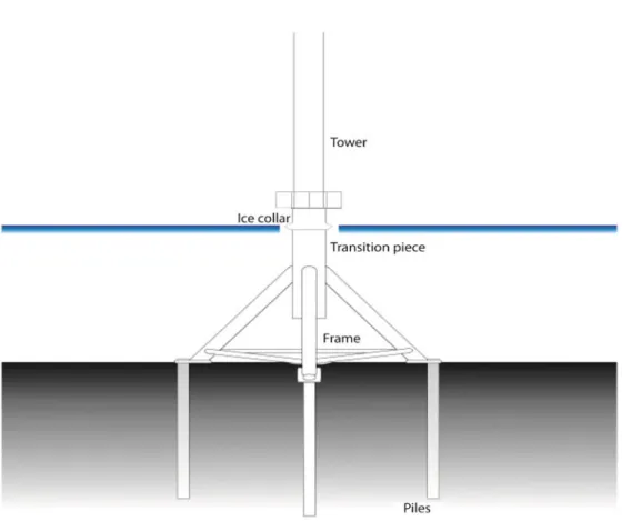
Figure 4. A schematic outline of a steel tripod foundation. The scale is not proportional; for details and dimensions see section 2.3.
2.3.1 General information of tripod foundation
The tripod foundation (Fig. 4) can be described as a monopile foundation in the water column, and eventually all the way to the bottom, where it is divided into a triangular frame of steel transition pieces. These are attached into the sediment with piles of smaller diameter compared to one simple monopile foundation. Due to this frame, the load is distributed across multi ple attachment points and a greater bottom surface compared with a mono pile foundation. The transition can also be placed over the water surface where three simple piles lead down in the water to their attachments.
The technical design of the tripod foundation may differ a lot between producers and due to the existing conditions such as depth, weight stress and bottom substrate. An estimation of weight for a tripod foundation (3 MW turbines) has been performed in a depth of 20 m and with a fairly hard sandy bottom substrate. 535 tons of steel were the calculated needed weight (SGS 2005). Another calculated weight with a depth of 40 m and a nonspecified bottom substrate, gives a weight of about 1 500 tons of steel. This is not including the attachment piles but only the foundation (WPD 2005).
The tripod foundation is attached by piling. Due to the smaller dimensions of the piles, the piling can be done with lighter piledrive equipments compared to the required piling work for the monopile foundation. The dimensions of the tripod piles depends on water depth, bottom substrate and the weight load, but generally they are in the size of Ø 3 – 4 meters (Achmus & AbdelRahman 2006; EWEA 2007). It is possible to replace the big piles by several smaller ones (about Ø = 1 m) (DWIA 2003). The construction work with tripod foun dations requires several steps and might take considerably longer time than the attachment of a monopile foundation.
In locations where great water movements at the bottom are present, a score protection may be needed (WPD 2005).
2.3.2 When is a tripod foundation used?
The tripod foundation is best suited on undisturbed sediment, but is adjusta ble to most bottom substrates (Dahlén personal comment; SGS 2005). Due to the piling, a tripod foundation is not a good alternative in areas with a lot of boulders (DWIA 2003). One of the greatest advantages of a tripod foundation is its ability to be used on deeper bottoms compared to gravity and monopile foundation and also, in general, there is no need for preprocessing the bottom before a tripod establishment.
At a depth interval of 20 – 40 m, the tripod foundation could be of tech nical and economic advantage (SGS 2005; WPD 2005). The dimensions of a tripod foundation is, like a monopile foundation, dependent on the impact of waves at the Swedish west coast and by the pack ice in the Baltic, where there is a greater cost per depth (DWIA 2005).
The technique of tripod is well tested in the offshore business (DWIA 2003) but has not yet (2007) been applied in the offshore industry, except for a smaller one made of concrete in Nogersund. In Alpha Ventus wind park (North Sea), tripod foundation is now under construction and this kind of foundation is given much attention in the investigations of new projection plans. With a future trend for deeper offshore establishments, the tripod foundation as an alternative is to be expected.
2.3.3 Applied summary of tripod foundation
The tripod foundation creates an artificial structure of higher complexity than both gravity and monopile foundations, which is of importance for marine organisms. Construction work does not, in general, demand any activity involv ing spreading sediment but the piling results in powerful/heavy and potentially harmful levels of sound. The list below is a summary of the relevant biologi cal information. The given dimensions are only to be looked upon as examples since the tripod design can be very variable.
Structure (for every foundation)
• Triangular frame with transverse ribs: creates a complex, artificial bottom surface consisting of steel girders which are painted (without anti-fouling components) and protected from corrosion with epoxy.
• Eventual ice collar: creates an artificial overhang by the water surface. • Eventual score protection: creates an artificial horizontal bottom surface
of stones or gravel.
• Eventual exterior cable in an exterior casing: can emit a smaller magnetic field and an induced electric field along the cable outside the foundation. • Anodes: exterior rods, containing mainly zinc, which are consumed and
replaced over time (see Information box 1).
Work of construction (for every foundation)
• Several pilings: creates very loud pulsating sound levels
• Activities from vessels including anchorage: noise and local bottom disruption
2.4 Jacket foundation
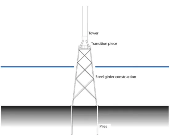
Figure 5. A schematic outline of a jacket foundation. The scale is not proportional; for details and dimensions see section 2.4.
2.4.1 General information of jacket foundation
The jacket foundation (Fig. 5) is composed by a squared network steel rods design, which is anchored in the bottom using piling activity. The technique is derived from oil platforms and is adapted for great depths. The rods of steel in the network are fixed together by welding or by the use of molded sleeves. Corrosion protection is achieved by using anodes, epoxy and/or galvanizing underneath the covering paint. The attachment of a jacket foundation takes place by piling 3 – 4 anchorage points in the bottom substrate, after which the whole steel construction can be mounted in one piece. A transition piece between the foundation and the tower is placed to distribute the weight (Dahlén personal comment).
In connection with the establishment of Utgrunden II (Baltic Sea), jacket foun-dation was developed to suit turbines of 3 MW and with a water depth of 20 m. The diameters of the steel pipes of these jacket foundations were calculated to 0.7 m for the outward bars and 0.5 m for the transverse bars (Dahlén personal comment). The anchorage piles to this jacket foundation were calculated to a diameter of 1.5 m.
In the year of 2006, the demonstration and research project Beatrice (Talisman Energy) was installed at a depth of 48 m in the North Sea, consisting of two 5 MW wind mills anchored on jacket foundations. Each foundation is 62 m high with 20 x 20 m at the base. Between the 4 corner beams is a network of transverse (45⁰) smaller beams. The weight of each foundation is about 750 tons (plus the transi-tion piece of 150 ton) and it is corrosion protected by epoxy and 72 smaller anodes (a total of 240 kg). In the splash zone (water surface area) all the steel is covered by sprayed aluminum. Both foundations are anchored each by four long piles (44 m) of the diameter 1.8 m (60 mm-thick steel) (Talisman 2006; EWEA 2007).
At the preliminary calculations for the wind park of Kriegers Flak (Baltic Sea), the weight of a jacket foundation at a depth of 40 m was roughly estimated as 700 tons of steel. As for the foundation at the project Beatrice, jacket foundations require a relatively low weight, which is favorable in an economical perspective in comparison with other foundations.
2.4.2 When is a jacket foundation used?
The jacket foundation is costefficient at greater depths (from 20 m) since they require less steel than for example the monopile and the tripod founda tions (WPD 2005). When used in shallow water it becomes generally more expensive than other foundations (Dahlén personal comment). One advantage of jacket foundation is that the anchorage does not require such heavy piling work as the monopile foundation.
After extensive investigations and comparisons with tripod foundations at the Beatrice project (North Sea, 48 m) it was established that jacket foun dations were a less expensive alternative than other foundations (Talisman
2.4.3 Applied summary of jacket foundation
The jacket foundation only occupies a smaller part of the natural bottom envi ronment, limited just to the 3 – 4 anchorage points. But the structural complex ity that is created by the multiform construction leads to a significant addition of habitats for many marine organisms and thus changes the natural environ ment. The aggregation of fish may also give a secondary impact on adjacent bottoms. The piling during the construction work creates heavy noise levels that might be harmful for the organisms in the surroundings.
The list below is a summary of the relevant biological information regarding jacket foundation. The given dimensions are only to be looked upon as examples since the jacket design can be very variable.
Structure (for every foundation)
• Steel construction: creates a multiform network of artificial bottom surface, consisting of steel rods (Ø 0.5 – 1m) which are galvanized and/or painted with covering paint of corrosion protection (for example glass flake epoxy).
• Exterior cable in a casing: can emit a smaller magnetic field and an induced electric field along the cable outside the foundation.
• Anodes: exterior rods, containing mainly zinc, which are consumed and replaced over time (see Information box 1).
Work of construction (for every foundation)
• Piling: creates very loud pulsating sound levels.
• Activities from vessels including anchorage: noise and local bottom disruption.
2.5 Other foundations
Besides the four basic models; gravity, monopile, tripod and jacket founda tions, suggestions of foundations based on a combination of these techniques have been developed. Examples of combinations are: gravity/pile, jacket/mono pile and tripod/monopile (SGS 2005). The technical design, the construction procedure and the relevant details of marine biology can be estimated on the basis from the four basic models described in the previous chapters.
Two additional models, bucket foundation (Fig. 6) and floating foundation (Fig. 7) are under development but have so far not been in use. The bucket foundation, which is hollow and can be resembled as a suction cup, is plunged to the bottom and is fixed in position with vacuum. This technique have so far been tested without success (Dahlén personal comment), but could possibly be of importance in the future due to continuous research within this area. A bucket diameter of 12 m has been deemed calculated to be suitable at depths of 10 m (EWEA 2007). In a marine biology perspective, the bucket founda tion is to be considered as a gravity foundation (see section 2.1).
Figure 6. A schematic outline of a bucket foundation. The scale is not proportional; for details see section 2.5.
The suggestion of floating foundations, designed with steel constructions which is fixed in position by wires anchored to the bottom, refer to future establish ments in deep water and has so far been estimated to be too expensive as alter natives in commercial use (WPD 2005). The idée of using floating foundation in the future is not considered impossible. A concept with simple floating founda tions for depths at 150 – 800 m is developed by the Norwegian Statoil Hydro. The part submerged is here made of 100 m deep concrete weights. Also another concept with three wind mills for every floating construction is under develop ment thru FORCE technology (EWEA 2007).
In a marine biology perspective, the floating foundations may come to resemble either monopile foundations (see section 2.2) or jacket foundations (see section 2.4). Though with a significant difference since the only contact with the bottom for floating foundation is by anchored wires.
2.6 Score protection
Score protection is made to prevent the local hydrographical changes that might occur around the foundation from digging out and undermine the bottom. It is calculated that a current velocity of 0.5 – 1.0 m/s causes erosion of the magnitude 1.3 times the pile diameter if the wave currents reach the bottom. Correspondingly erosion without the waves is 0.5 – 1 times of the pile diameter. In bottoms with sandy substrates, this erosion might take place in a couple of hours while the same erosion could last for hundreds of years in muddy bot toms (Nielsen personal comment).
The erosion control used so far for the offshore wind mills generally consists of a lower layer of gravel and an upper layer of stone, which is placed out from the anchorage point of the foundation to a suitable distance (in the range of 5 – 10 m). The size of the score protected area is decided by the hydrographical conditions such as under surface currents and waves. An example of score pro tection of 5 – 10 m from the foundation is found at the wind park of Kentish Flats (North Sea) and has proved to be effective (OES 2007). However, at the wind park of Horns rev significant erosion has occurred despite using a simi lar technique. Reasons for this are under investigation (2007) (Nielsen per sonal comment).
A score protection is always required for gravity foundations since even a slight change would result in significant instability. The piling foundations (monopile, tripod and jacket foundation) do not require score protection since they can be adjusted for erosion. The adjustment is done by extending each pile with the same number of meters which erosion is expected to dig out (EWEA 2007).
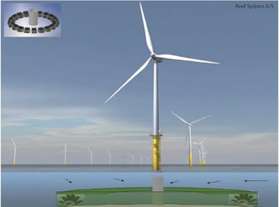
In addition to score protection of gravel and stones, specially designed protec tion has been produced. One example is “GRIP” by Reef Systems, which is a combination of score protection and artificial reef (see Fig. 8). The GRIP con sists of concrete modules, equipped with protruding plastic tubes. Its capacity as score protection is not yet evaluated (Reef Systems 2007).
The impact on the marine environment from score protection is the extensive heterogeneous hardbottom substrate, with many cavities, which is produced. The structure creates opportunities for the establishment of the organisms associated with hard bottom substrate and protective structures (see section 3.1).
Figure 8. Artificial score protection, GRIP, adjusted to increase the amount of habitat for fish and bottom living animals associated to hard bottom substrate –by the reef-effect. Each module con-sists of a perforated concrete pipe lined with protruding plastic pipes.
3 Sources of influences
Offshore wind is an expanding business where marine resources are used and its environmental impact is now widely investigated by gathering experi ence and knowledge. This gathering of information is achieved by monitor ing programs and through experimental studies. Extensive control programs have been carried out at the Danish wind parks of Nysted and Horns reef. The environmental impacts of the offshore wind parks in Sweden are stud ied at the wind park of Lillgrund (Öresund) and new control programs are planned for coming offshore wind parks. Targeted research with experimen tal studies and literature syntheses are in progress in several countries; for example in Sweden (Vindval), United Kingdom (COWRIE) and USA. A larger number of literary compilations have also been produced regarding envi ronmental impacts from offshore wind; through authorities (Fiskeriverket/ Swedish Board of Fisheries 2007; Jonasson 2002; Petersson 2000), through scientific papers (Gill 2005; Petersen & Malm 2006), through research pro grams (Michel et al 2007; Nedwell et al 2003; Nedwell & Howell 2004; Gill et al 2005; Thomsen et al 2006) and through the Environmental Impact Assessments for the different offshore wind projects.
Thus, the total current knowledge is increasing but instead of looking at the environmental impacts, this study focuses on comparing how the dif ferent designs of the foundations relate to environmental impacts; describ ing the technical factors that can increase or decrease the various sources of influences. The sources of influence discussed here are compared between the different models of foundations regardless of which of the sources that will appear to be significant in the future.
The following section deals with every source of influence by 1) a short summary of the mechanisms, 2) the difference between sea areas, 3) the differ ence between various foundations, and 4) any adjustments that may be taken to minimize negative impacts. The following sources of impacts are discussed:
• Fouling and reef-effect (3.1)
• Noise during operational phase (3.2) • Hydrographic changes (3.3)
• Construction noise (3.4)
3.1 Fouling and reef-effect
3.1.1 Background
During the establishment of offshore wind parks, the foundations and the score protections are expected to create new habitats for the hard bottom living algae and animals. This in turn results in the increase of the biological biodiversity in the area. Artificial hard bottom habitats with the function simi lar to natural hard bottoms are called artificial reefs, and have been proven to be substrate for sessile algae and animals (Anderson & Underwood 1994; Conell & Glasby 1999; Jensen et al 2000; Glasby & Conell 2001; Svane & Petersen 2001; Bacchiocchi & Airoldi 2003; Knott et al 2004; PerkolFinkel & Benayahu 2005; Boaventura et al 2006). Fouling on the reefs creates new habitats and an increasing access of food for fish and other mobile fauna. The new habitat does not only create a larger availability of food but also creates shelter against strong currents and predators. This will increase the number of mobile fauna concentration, such as fish, near the reefs and a so called reef effect is created.
There is documentation of reefeffects on artificial reefs from both south and north Europe (Jensen et al 2000) and other parts of the world. This is now used, for example, in Japan and in USA in an attempt of increasing the catch of the commercial fish (Buckley 1982; Grove et al 1989; Milon 1989). The reason for the increased fish catch has been discussed. Whether it is only a gathering of fish or if it is an increase of fish production is hard to determine (Bohnsack 1989; Pickering & Whitmarsh 1997; Svane & Petersen 2001) but the reality most likely reflect a combination of both theories. The reason for the increase in fish abundance may also vary between different species.
The development of a hard bottom is created gradually when animals and plants are established at different times of the year and has a range of how competitive they are (Gaines et al 1985; Underwood & Anderson 1994; Qvarfordt 2006). A so called biofilm of microorganisms are created on a newly formed substrate, and this can make the establishment of larger organ ism’s easier (Wieczorek & Todd 1998; Unabia & Hadfield 1999). During the initial phase, the opportunists are generally colonizing the substrate. These are characterized by; fast reproduction, fast growth and are widely dispersed geo graphically. The opportunists are in general not competitive regarding space and after some time species with longer life cycles, which also generally are more competitive, are established. This leads to a changing species composi tion with time until stabilized conditions are reached (Dean & Hurd 1980; Wennberg 1992; Qvarfordt 2006). It may take several years before a stabiliza tion of a hard bottom community is reached and this is important to take into consideration before making any conclusions of diversity, abundance and bio
definitions
Fouling, a production of sessile plants and animals is here separated from the reef-effect which is defined as an increasing availability of mobile animals with a result of either an aggregation or an increased production. See Fig. 9
Figure 9. Fouling (left) and reef-effect (right) on a monopile foundation at the Utgrunden I. The structure to the right is the anchorage ladder on the transition piece of the foundation. The photos were taken on a depth of 5 – 6 m during August. They show a rich fouling of blue mussels and a high presence of two-spotted goby.
The main difference between a foundation of a wind mill and many other artificial reefs is the vertical structure that goes through the whole water column, from the surface to the bottom. A depth related zonation is created where both the deep living animals and the light demanding animals could be established. Other artificial reefs, that resemble foundations of wind mills, are bridge poles, piers, oil platforms and lighthouses.
The location of an offshore wind park is generally exposed and the plankton larvae and spores passing by with the water mass are more easily stuck on the verti-cal structure against the current and may colonize the free sites. This is especially good living conditions for filtrating animals, since the current contribute with plank-tonic food. The current is consequently an important factor in the development of a biological hard bottom community.
The design of the foundation with the adherent erosion protection (vertical, slop-ing and horizontal surfaces) and the structure of the surface (smooth or rough) are initially of importance regarding which kind of species that will establish on the foundation. The surfaces that are sloping or horizontal create different conditions than vertical ones, especially for light-dependent algae. Perennial macro-algae that
are commonly found on shallow bottoms are limited when there is a sharp slope of the substrate. Studies in the Baltic Sea have shown that the algae dominate the substrate when the slope is less than 60⁰ (degrees). Between 60⁰ and 90⁰ in angle inclination, the organism community gradually changes and is dominated by filtrat-ing fauna. Some of the species are excluded already in the establishment phase, for example the important Fucus vesiculosus which has less than 1% successful settling when the angle is steeper than 60⁰ (Qvarfordt 2006). The distance to the bottom is also of importance for the presence of some macro-algae since their heavy prop-agules easily sinks to the bottom in calm water after leaving the mother plant. One might see a result of this on large boulders where there is less recruitment of Fucus vesiculosus (Qvarfordt 2006). Some macro-algae are also limited by a high exposure due to waves and currents (Kautsky & van der Maarel 1990; Kautsky and others 1992; Nielsen 2001).
The structure of the erosion protection may contribute with small and large cavi-ties, which enlarge the given conditions for fish and crayfish around the foundations. These various cavities can be utilized by different species and different life stages (sizes) of the same species. For example; lobsters and crabs can utilize both small and large cavities depending on which life stage they are in.
The surface structure of a foundation, originally, differs from natural hard bottoms in their lack of microhabitats such as indentations, crevices, cracks and bumps, which provide habitats for many species and create shelter against predators (Mc Guiness & Underwood 1986; Chapman 2003). Steel and treated concrete give the foundation a smooth surface, which makes it more difficult for many animals and plants to settle, while a rougher surface like the untreated concrete has a more resemblance to a natural bottom and so it is a more attractive habitat for many organisms (Harlin & Lindbergh 1977; Lubchenco 1983). Concrete may also leak calcium hydroxide, which may benefit the establishment of some organisms (Anderson 1996). Even if the biological com-munity development may proceed quicker on a rough surface initially, the structure of the surface and by that also the species composition will level out when the species begin to grow over each other. Some species like the barnacles (which produce glue in order to attach themselves to the substrate) and the calcareous worms are more easily established directly on a smooth homogeneous surface than other organisms and are therefore creating a coarser structure. These organisms may later be overgrown by other species (Öhman & Wilhelmsson 2005). The initial differences can thus be explained by different surface structures, but if the differences remain after a longer period of time it might have other physiological and biological factors that are of importance.
Species colonization on offshore wind park foundations are dependent on the location of the park; east or west coast, exposed or sheltered, prevailing bottom sub-strate, depth and also closeness to natural hard bottoms.
There is a great salinity variation between the Swedish east and west coast, and it is important to pay attention to this while comparing the offshore wind parks in Sweden since salinity has a significant role for marine organisms and thus for
which are found closer to the shore. Comparative studies in Kalmarsund, Öresund and at Gotland and Öland show that filter feeding animals dominated in areas with strong currents and that filamentous algae, which benefit from eutrophication, were more common close to shore (Naturvårdsverket, Environmental Protection Agency, 2006a). The ecological changes of an offshore wind park are more apparent when placed on a soft bottom (clay, sand, gravel) than placing the wind park where there is an existing hard bottom. The new habitat on the soft bottom attracts new species for the area, and so it changes the ecological conditions (Jensen et al 2000; Bulleri 2005). But it takes several years before a new hard bottom community is stabilized. How rapid the development of a hard bottom community is, also depends on the dis-tance to a natural hard bottom.
Planktonic life stages of animals have different length of life in the free water mass depending on species and they are spread to new areas with the currents. When a new hard bottom substrate is created in soft bottom areas, hard bottom species can use this new substrate as a “stepping stone” and it will be easier to cross soft bottoms and deeper areas for establishment on new hard bottoms which then can be within reach (Glasby & Connell 1999). The effects of this may be both positive and negative depending on the spe cies and the area. Alien (introduced) species can be spread to new areas in this way and can affect the local ecology. The success of the species establish ment depends on the survival in the planktonic phase before it reaches the free space and their ability to establish on the substrate and in the area. An exam ple of an introduced species is the amphipod Jassa marmorata which invaded the foundations of Horns rev on the Danish west coast where it was previ ously unknown (Leonard & Birklund 2006). This amphipod depends on hard bottom substrate, which is naturally scarce along the west coast of Jylland (Denmark).
The reef effects in terms of increased fish abundance have been found at the foundations of Utgrunden I and Yttre Stengrund in the Baltic Sea. Some species, especially smaller fish species, were concentrated nearby the foundations. This was also observed at the bridge of Öresund (Öhman & Wilhelmsson 2005). During the investigation close to the foundations of Horns rev and Nysted, larger fishes were observed, including cod (Leonard & Birklund 2006). Other studies have been looking at the fish abundance on a larger scale, with no focus close to the foundations but between the foundations within the whole wind park area. Comparative studies at the Horns reef and Nysted have not so far shown any significant effects and increased abundance or species richness of fish among the foundations in these wind parks (Klaustrup 2006). The Kentish Flats control program results (North Sea) indicate general increased fish abun dance within the park. This result has not been analyzed statistically and there are no studies done close to the foundations (Emu 2006). All in all, it is difficult with the present knowledge (2007) to state to what extent reefeffects occur in a wind park. However, an increase in fish abundance at artificial constructions it is a common occurrence and is to be expected also in the wind parks.
A more detailed presentation of different studies that have been done with foundations, bridge poles, oil platforms and other artificial reefs is given in Information box 2. This gives an indication on how the organism communi ties may develop in various areas and on different types of foundations. The conclusions in the section below, dealing with the differences between ocean areas and foundations are mainly based on the information and the references presented above and in Information box 2.
Figure 10. The soft coral (left) is a common marine fouling deeper down on the foundation or score protection. Tube building amphipods of the Jassidae family (right) often creates dense mats on exposed foundations.
3.1.2 differences between sea areas
When a wind park is located in an exposed area, regardless if it is on the Swedish east or west coast, the dominating animal group is filter feeders. The lower salinity in the Baltic Proper does, however, result in fewer filtering spe cies, and the absence of certain predators means that a monoculture of the common blue mussel is to be expected over time. If there is a high abundance of seabirds, which can consume large amounts of blue mussels, the mussels will have a limited distribution and other species may become established. In the areas where the low salinity limits the blue mussels, for example in the Gulf of Bothnia, it is rather the filamentous algae that are expected to domi nate on the foundations. The limiting factor for the distribution of blue mus sels on the west coast could be the depth. This may lead to a hard bottom community with higher species richness and a zonation in depth. Potential
consistent with the authors’ personal observations at the wave power park at Islandsberg in the Skagerrak, where the tube building amphipods (Jassa pusilla and J. falcate) dominated the fouling of the plastic covered wires (see Fig 10). In the upper meters of the foundations, blue mussels can be abundant, probably because low predation pressure from seabirds and also because other predators like sea stars and crabs cannot establish in high exposure areas.
Exposure resistant algae may occur on foundations in both the Baltic Sea and on the Swedish west coast, with a variation in species composition depend ing on nutrient load and level of exposure. In places where the light penetrates deeper down, like on offshore banks, and if the erosion protections are not exposed to high exposure, even larger algae as bladder wrack and other kelp species may become established. The reefeffects, i.e. an increased concentra tion of mobile animals around the foundations, are expected to occur irrespec tive of sea area, with higher species richness in the North Sea as a result of higher salinities.
If a wind park is located in stagnant water or on a depth where the foun dation reaches below the halocline, an increased deposition of organic matter may result in oxygendeficient bottom water and hydrogen sulfide could, in the worse case, form at the base of the foundation. This may then have a neg ative impact on the local benthic fauna. The likely occurrence of oxygendefi cient bottoms around the foundations is thus dependent on local conditions, such as depth and level of exposure.
3.1.3 differences between various foundations
Whether the surface structure consists of concrete or steel, studies have demon strated that different adhering organisms can establish on the vertical foundations. Concrete gravity foundation at Nysted Wind Park has proved to be an excellent substrate for filtering animal groups. This has also been found on steel monopile foundations at Utgrunden I, Yttre Stengrund, Horns reef and at the wind park of North Hoyle outside the west coast of England. Establishments of filamentous algae have also been successful closest to the surface of the foundations.
Differences between various structures may arise initially and this is deter mined by the availability of larvae and their availability to establish (“settle”). But gradually, as the biological community is built up, the species composition changes and more competitive species grow over other species and may be domi nant until a relatively steady state finally arises. After a number of years, regard less of the initial surface structure of the foundation, the expected attached algae and fauna will be similar on the different foundations located in areas with the same level of exposure and salinity.
Different design of the foundations, with both vertical and more horizon tal surfaces, may result in varying development of the biological community, mainly because of the algae which more easily establish on angled surfaces where the light exposure is higher.
Jacket foundations, in particular, and partly tripod foundations have a more complex structure with far more sloping surfaces which is suitable for
light dependent algae. In a study of a jacket foundation the research flat form FINO 1, the only jacket foundation studied so far (2007), it was observed that attached filter feeders and tube building amphipods dominated due to the exposed location despite potential suitable sites for the algae. In areas with weak currents, where the conditions for the filter feeders are less suitable, other species may establish. In this case, if the light availability is sufficient, the algae are expected to establish on the sloping and horiozontal (score pro tection) surfaces of the foundation.
The top meters on the gravity foundation consists of a so called overhang. The light is limited here and the exposure is high, which is a disadvantage for the algae but creates an attractive site for filter feeders. Regarding the gravity foundation, an immersion of the sea bed is made which may result in covering parts of the erosion protection with sand. This was shown to be a disadvan tage for the otherwise dominant blue mussel at the Nysted wind mill park, thus benefiting other species.
The conclusion is that the salinity, level of exposure, depth, distance to land and light availability primarily determines which attached species will dominate at the established wind park. The effects of the design and the structure of the foundation are only secondarily factors that determine the species composition; the filtering animals are in general benefited but shallow horizontal structures and low level of exposure might benefit macro algae.
As a habitat becomes more complex, the more attractive it will be for the mobile fauna such as fish and crustaceans, since there is plenty of cavities and sites to settle. Jacket foundations and tripod foundations is thus a more attrac tive reef than a more compact and homogeneous structure like the one of monopile foundations. Abundant reefeffects have been observed on oil plat forms around the world and the structures of these are similar to jacket foun dations. Even more deep living species might exploit the food availability and the various habitats of the artificial reef of jacket and tripod foundation since they are planned to be placed at greater depths.
Associated erosion protections can be designed to benefit the reefeffects, and this may compensate for the plane surface of monopiles and gravity foun dations. A multiform score protection with both large and small cavities creates habitats for several species and for different life stages within the same species. This may create favorable conditions for crustaceans and fish among others.