Mälardalen University
School of Innovation, Design and Engineering
Bachelor thesis in Computer scienceWide area motion capture using an array of
consumer grade structured light depth
sensors
Author: Karl Arvidsson Supervisor: Afshin Ameri Examiner: Baran Çürüklü October 20, 2015Abstract
In this thesis we propose a solution to how a system can find and track people, as well as recognizing their gestures, in a 360◦ field of view using consumer grade products. We describe a system connecting multiple depth cameras in an array and have them operate as a single camera controlled by a single computer. Using a single camera providing features such as detection, tracking and recognizing gestures of people, we specifically focus on the difficulties of preserving these features in moving forward to an array of cameras. We propose a solution based on Microsoft Kinect and Kinect SDK, using linear transformation to account for a fixed camera model to combine skeleton data from an array of Kinect sensors. Furthermore, we use positional based identification to determine whether people are being tracked by another camera in the system. The contributions of this work include insight into the challenges of building this kind of system based on Kinect hardware and software intended for use on a single computer, such as performance bottlenecks, along with possible alternative solutions. In particular, we present performance measurements for a single computer running up to four sensors and show a system that can run satisfactorily with up to at least 5 sensors on today’s computers. We show what requirements on hardware can be expected for such a system, as well as where there are potential limits as the number of sensors increase.
Sammanfattning
I den här rapporten beskriver vi ett system som sammankopplar ett flertal avståndssensorer för att fungera som en på en dator. Givet en ensam sensor med funktioner som upptäckande, spårande och igenkänning av gester, fokuserar vi mer specifikt på svårigheterna med att pre-servera dessa funktioner när vi går vidare med en samling sensorer. Vi föreslår en lösning baserad på Microsoft Kinect och Kinect SDK, där vi använder linjär transformation för att ta hänsyn till en fast kameramodell när vi sammanställer skelettdata från en samling Kinect-sensorer. Vidare använder vi positionsbaserad identifikation för att avgöra om människor redan aktivt spåras av en annan kamera i systemet. Bidragen från det här arbetet inkluderar insikt i utmaningarna med att bygga ett sådant system baserat på Kinect-hårdvara och mjukvara ämnad för körning på en dator, såsom prestandaflaskhalsar, tillsammans med möjliga alternativa lösningar. Mer specifikt presenterar vi prestanda-tester för en ensam dator som kör upp till fyra sensorer och visar ett system som kan köra tillfredsställande med upp till minst 5 sensorer med dagens da-torer. Vi visar vilka krav på hårdvara som kan förväntas för ett sådant system, same var det finns potentiella gränser när antalet sensorer ökas.
Contents
1 Introduction 4
1.1 Problem Statement . . . 4
1.2 Project goals . . . 5
2 Background and related work 6 2.1 Depth detection . . . 6 2.2 People detection . . . 7 2.3 Gesture recognition . . . 7 2.4 Linear transformation . . . 7 2.5 Ethics . . . 8 3 Methods 10 3.1 Motion capture with a single camera . . . 10
3.1.1 Microsoft Kinect . . . 10
3.1.2 Kinect SDK . . . 11
3.1.3 User Interface . . . 11
3.2 Multiple cameras simultaneously . . . 12
3.2.1 System setup . . . 12
3.2.2 Overlapping field of view . . . 12
3.2.3 Performance . . . 13
3.2.4 Combining the data . . . 14
3.3 Recognizing gestures and specific movement . . . 16
3.3.1 Identification . . . 16
3.3.2 Gesture recognition . . . 17
4 Results 20 4.1 User interface . . . 20
4.2 Tracking with an array of sensors . . . 20
4.3 Gesture recognition . . . 21 4.4 Performance testing . . . 21 4.4.1 Test results . . . 27 5 Conclusions 30 5.1 Future work . . . 30 5.1.1 Camera model . . . 30 5.1.2 Identification . . . 30 5.1.3 Gesture recognition . . . 30 5.1.4 Performance . . . 31 2
1
Introduction
In recent years, there have been tremendous changes in human computer interaction. Not long ago people were used to interacting with their mobile phones through buttons and a small monochrome display. The larger capacitive displays in use today provide interaction on a more intuitive level by allowing users to manipulate objects on screen through touch. Along with touch screens, progress has been made in other methods of human computer interaction; accelerometer based gesture recognition as seen in the Wii Remote1 and mobile phones, speech recognition and voice commands such as Siri2, and motion capture and gesture recognition seen in Microsoft Kinect3.
These advancements have had a significant effect on social aspects of modern society and will likely continue to contribute to improvements in education, medical, military, surveillance and entertainment technology[34][39][40][41][42].
This thesis is part of a system used to allow people to interact with objects using gestures. In particular, we focus on the underlying part of this system; detecting people, tracking them and extracting information about how they are interacting (such as gestures). The system then provides this information to the part of the system responsible for responding to those actions. The challenge lies in building a system that can detect and track people in a 360◦ area around a small object, as well as recognize gestures and other information about these people. Also, we limit the hardware to a single personal computer as an attempt at maintaining accessibility for consumers.
The complete system aims to provide a collaborative experience to the audience by creating soundscapes based on this interaction. The experience is centered around an object; people who enter the vicinity of the object will be detected by the system and be given a role within the experience. Based on their interaction through movement and gesture, and their assigned role, audience members can produce different sounds. These can be ambient sounds, musical pieces, effects (such as thunder or car sounds) or other sounds. The role is nothing more than an assignment of a task to a certain audience member. In other words, the intent is to have each member of the audience to be responsible for a specific part of the overall soundscape. For example, one person may be assigned a drum sound. The intensity, tempo and timbre of the drum sound may then be the variables that the person can control through the interaction. The intended environments are places like museums, exhibitions or art galleries. As such, the complete system can serve as a source of entertainment, an exhibition or a promotional tool aimed at participants in these environments.
1.1 Problem Statement
This thesis project aims to solve the problem of connecting multiple sensors together and have them operate as one. In other words, we want to find an answer to the question “How can a
system find and track people, as well as recognizing gestures performed by those people, in a 360◦ field of view using off-the-shelf products”.
1
The Wii Remote is the controller for the game console Wii[38] created by Nintendo
2Siri[33] is a voice controlled assistant application for Apple iOS, the operating system of the iPhone mobile
device.
3Microsoft Kinect[34] is a sensor developed for use in games as an alternative type of controller. It is further
1.2 Project goals
Our approach to finding answers to the above question is to develop a system capable of observing an area and providing specific information about people observed in that area. The goal is to deliver a prototype application meeting the following requirements:
1. The system should facilitate the use of up n sensors, where n is the number of sensors required to cover a 360◦ field of view (realistically expected to be six or less).
2. The system should be able to run on a single personal computer.
3. Each sensor should be able to track people exactly as if it was used independently. 4. Each sensor should provide positional information about each of the persons it is tracking,
with respect to its own coordinate space, exactly as if it was used independently.
5. Each sensor should provide joint (or body) information for each of the persons it is tracking, exactly as if it was used independently.
6. The system should be able to infer speed and direction of each of the persons tracked by each of the sensors.
7. The system should be able to, based on the provided joint information, recognize gestures performed by any of the persons tracked by any of the cameras (gesture examples include waving, jumping, swiping and raising arms).
These requirements are based on what is given as base functionality from a single sensor. Details and reasoning behind these are discussed further in section 3. With a prototype meeting the above requirements, we will have successfully preserved the functionality of a single sensor within an array of sensors, as well as added additional features required to recognize gestures.
2
Background and related work
There exists methods to achieve accurate tracking and gesture recognition using equipment worn by users. However, for our purposes it is of course not suitable to use these methods. Therefore, we look at other technologies and different kinds of cameras that can meet our needs without the equipment restriction, with the probable loss of accuracy and speed. First, we look at time-of-flight cameras and how they operate; we then discuss various methods of people detection followed by methods of gesture recognition. Furthermore, we discuss linear transformations to prepare the reader’s understanding of concepts used to solve later problems discussed in section 3. Finally, we discuss ethics related to surveillance in public places.
Surveillance was one of the first applications of video cameras. The closed-circuit television (CCTV) system, a system often used for surveillance, was invented many years before it was possible to cost-efficiently store video recordings. Until then, a person had to manually observe the video feed from surveillance systems. With advancements in technology, increases in use followed. Today, cameras used for surveillance purposes are widely utilized by governments, military, police, civilians and more. Many systems also employ automatic analysis in order to find information about the surveyed area, such as people detection and facial recognition [1] [2]. These methods of analysis are also related to recent advancements in motion capture tech-nology where motion tracking is accomplished solely by the use of cameras and no equipment worn by users. The video game industry has played a pioneering role in making this technology commercially available in recent years, creating opportunities for average consumers to experi-ment with technology that was previously unavailable or very expensive. This project tries to extend on these advancements.
We define “player” as a person actively being tracked by one or more cameras.
2.1 Depth detection
There are several methods of finding depth information with cameras. In this section, we will discuss three examples; stereo triangulation, time-of-flight and structured light. In stereo triangulation, a stereo camera (a camera with more than one lens) is used to essentially compare two images and find corresponding points. This method is fast enough to be used in real time and is often employed for use in robotics [43]. However, it has difficulties correctly measuring depth for points in image regions where points are hard to discern from others (i.e. one color walls) [5]. These properties would suit the needs of this project; since we are tracking people, who are easily discerned from walls, the disadvantage of stereo triangulation should not cause any problems.
A time-of-flight camera is a range or depth camera that produces images holding distance data for each pixel by measuring the time it takes for light to travel between a point and the camera [3]. This type of camera can build a complete frame with only one shot and is able to operate at high frame rates , making it ideal for real-time applications [4]. However, time-of-flight cameras are often poorly calibrated and suffer when multiple cameras illuminate the same area, causing the light pulses used for measurement to interfere between the cameras [5]. There have been attempts at combining time-of-flight methods with stereo cameras in order to gain advantages from both solutions as described by [5]. Fortunately, it is relatively easy to distinguish a human body from the environment with the range images provided by a time-of-flight camera [4]. Since there are no extreme need for accuracy for our purposes, time-of-time-of-flight cameras should be a good fit.
The structured light method measures depth by projecting a known light pattern on the scene. Looking at the projected pattern, it calculates depth by utilizing triangulation. The light pattern makes up for most of the weakness of stereo triangulation mentioned above, but it suffers from the same interference problem as time-of-flight cameras. Multiple light patterns projected on the same surface of course increases the difficulty of recognizing a known pattern.
Like the time-of-flight camera, an entire scene can be captured in one frame, making this method suitable for real time applications. This method is employed by some consumer grade depth sensors (examples include Microsoft Kinect) and is a good fit for our purposes, supporting real time capture and has relatively high accuracy.
2.2 People detection
In this section, we will discuss approaches to detecting people in images. We also evaluate if these are suitable for the goals of this project.
Detecting people in still images is a very difficult problem; most people detection solutions are based on inspecting changes (or motion) [6]. A robust and fast method involving using mixtures of Gaussian distributions to determine if a pixel is part of the foreground or background has been presented in [7] and used by [8] in an attempt to track groups of users and recognising certain events, such as counting people crossing a certain area.
Many recently developed methods employ depth cameras (or time-of-flight cameras, ex-plained above) to divide a scene into foreground and background. Ikemura et al. presents a system using time-of-flight cameras to detect people by comparing similarities between depth histograms [9]. The depth histograms are created by dividing the depth image into regions of 8 x 8 pixels and the depth information for those pixels. Each region has a corresponding depth histogram. The similarity is calculated from the Bhattacharyya distance [10].
Others have combined methods from color image processing and depth image processing as presented by [11]. With inspiration from Histogram of Oriented Gradients [12], used to analyse color images, they developed a method called Histogram of Oriented Depths (HOD) and Combo-HOD. These methods are suitable for this project since they are highly accurate and able to run in real time.
2.3 Gesture recognition
Gesture recognition is most often accomplished by a user wearing equipment, such as gloves or suits with passive or active marker for recording positional data. However, since equipment-based techniques are unsuitable for our purposes, we focus on solutions equipment-based solely on visual information. Rigoll et al. presents a method based on dynamic pattern recognition with hidden Markov models, a statistical stochastic model, in [13]. With the help of statistical analysis, they were able to achieve recognition of 24 gestures (such as waving, spinning and pointing) performed by 14 different people with a 92.9% success rate. Hidden Markov models are commonly used to recognize gestures; the models are trained using examples of performed gestures. Statistical analysis can then compare new gestures to the “known“ set of gestures. This approach makes hidden Markov models well suited for gesture recognition applications [14]. Other methods attempt to extract positional and orientational information using a time-of-flight camera in order to recognize hand gestures [15].
2.4 Linear transformation
This section will describe linear transformation to introduce the reader to concepts and knowl-edge necessary for understanding some proposed solutions. Linear transformation is utilized in this project to solve problems related to positions in a coordinate space. Linear transformations are widely used in computer graphics to translate (or shift position), rotate and scale objects or coordinates in a 2D or 3D vector space. A linear transformation between two vector spaces V and W is a map T : V → W such that the following hold [16]:
1. T (v1+ v2) = T (v1) + T (v2) for any vectors v1 and v2 in V . 2. T (cv) = cT (v) for any scalar c.
Linear transformations can be represented by matrices, and for our purposes only translation and rotation are required. These constructs are presented here:
Tvp = 1 0 0 vx 0 1 0 vy 0 0 1 vz 0 0 0 1 px py pz 1 = px+ vx py + vy pz+ vz 1
The translation matrix, with offset input defined by v is multiplied with position vector p. The result is p shifted by the offset defined by v [17].
Rotation is perfomed about one of the axes of the coordinate system. The following rotation matrices can be used to rotate a vector by an angle θ about the respective axis [18]:
Rx(θ) = 1 0 0 0 cosθ −sinθ 0 sinθ cosθ Ry(θ) = cosθ 0 sinθ 0 1 0 −sinθ 0 cosθ Rz(θ) = cosθ −sinθ 0 sinθ cosθ 0 0 0 1 2.5 Ethics
It is necessary to discuss ethics when undertaking constructing a system related to surveillance and personal privacy. While it is not illegal to capture recordings in public places4, it can cer-tainly be considered ethically questionable. Few people seem to become bothered by surveillance systems in, for example, subway stations, where the purpose is often safety reasons. [47] argues that this stems from people not maintaining an expectation of privacy in these spaces. Although, if even more widespread, this type of security can be perceived to be incriminating on personal privacy, as noticed with the extensive increase in CCTV surveillance in the United Kingdom in recent years[45]. People worry about personal privacy when they do not know what recordings of them are being used for, or in what context those recordings will later be portrayed [46]. This is also related to the data gathering of user information among various social networks and the ignorance of who can access that data. The context in which a person is being recorded in a public place therefore almost acts as an agreement or an announcement over the purpose of the recording. It follows that people should be comfortable with using a system like the one presented in this thesis. The assumption is that people see it purely as a game where none of the recorded data is kept for other purposes (the proposed system does not store any recorded data. It simply captures, analyzes and then discards the recordings).
4
In Sweden, the act of capturing technical recordings in public places is protected by The Fundamental Law on Freedom of Expression[44]
3
Methods
In this section we describe the development of the prototype system. We discuss products, technology and solutions to the challenges encountered in solving the proposed problem. The development methodology has been loosely agile. Improvements and features have mostly been added and refined iteratively and incrementally. However, no particular existing method was used. The development process itself has not been analyzed or heavily managed through the course of the development process (that is, methods such as Scrums sprints and product backlog has not been used).
3.1 Motion capture with a single camera
The first step towards building an array of cameras capable of tracking several people is tracking a single person with a single camera. This section will discuss single camera solutions. Further-more, we will also describe the foundations of the prototype system for multiple cameras, since it is an extension of a single camera system.
3.1.1 Microsoft Kinect
While there are many depth cameras capable of motion tracking available commercially, Mi-crosoft Kinect is a good fit for our purpose. It has both an RGB camera (a camera that captures color images much like a regular video camera) and a depth camera. Both of these cameras operate with a frame rate of 30 frames per second. The depth camera calculates depth by looking at a pattern projected by an infrared projector and utilizing stereo triangulation be-tween the camera, projector and the known pattern [21]. Kinect also provides people recognition and tracking of up to six people simultaneously, while providing joint tracking information for two out of those six. However, the depth camera is able to discern people from other objects only within the range of approximately 0.8 - 4m. Both the RGB and depth cameras are limited to a field of view of 57◦; discussed further in section 3.2.2. The range limitation poses concerns for our purposes. Ideally, the minimum range should be small enough for people to stand very close to an object that is roughly in the same position as the camera, almost touching it, and still be trackable. The maximum range might be insufficient if only one camera were to be used, but if several cameras cover an area 360◦ around an object, 4m in each direction should be enough for a small audience. In general, a good guideline seems to be no more than two people for, or in front of, each camera. Not only because Kinect only supports joint tracking for a maximum of two people, but also the small field of view available for each camera. The technical details described here, and further details, are available in Microsoft’s Human Interface Guidelines document [19] and the technical specifications of Kinect sensors [20].
3.1.1.1 Zoom lens The minimum range limitation can be fairly reduced by using a lens to alter the cameras field of view. A commercially available lens fitted for Kinect is the Nyko Zoom lens, marketed as able to reduce the distance required between a user and a Kinect sensor by up to 40% [22]. In reality, the Zoom lens reduces the minimum distance to approximately 0.6m (or reduction by 25%), which is still slightly higher than what would be optimal. The Zoom lens is a fisheye lens, or a wide angle lens that does not produce rectilinear images. That is, images of objects with straight line characteristics may not portray straight, but rather curved or bent, lines. Therefore, in addition to the “zoom out” effect of the fisheye lens allowing for the reduced minimum range requirement, the images are heavily distorted; especially at the outer edges of the lens’ field of view. Since the depth frame images are now distorted, the infrared pattern is also distorted. With the increased difficulty for the depth camera to recognize the pattern, a lot of noise is introduced to the depth frame images. While the center of the camera field of view is relatively unchanged, the edges are warped to a point where Kinect’s ability to detect
and start tracking a person is significantly reduced. However, once detected, a person can be tracked even at the edges, effectively increasing the cameras field of view. We will discuss this further in section 3.2.
3.1.2 Kinect SDK
Many computer vision libraries are available to facilitate application development with Microsoft Kinect. Other than the official SDK, the most well known is likely OpenNI, an open source framework supporting a variety of different 3D sensors. There are pros and cons to any choice; OpenNI’s support for gesture recognition is superior to that of Kinect SDK (where it is non-existant). However, Kinect SDK provides an intuitive framework for the basic purposes of this project. That is, providing people detection, tracking and managing of that data out of the box. Kinect SDK provides three sources of data from the cameras to the developer; one for the RGB camera, one from the depth camera and one skeleton data source compiled automatically by Kinect from its depth data. These are called the color stream, depth stream and skeleton stream, respectively, and will be referred to by these names from this point. The skeleton stream provides collections of joint nodes of the current people being tracked by the camera. The joint nodes contain information about where in 3D space the joints are located and how they are rotated with respect to the other joint nodes of that person. Together, all joint nodes belonging to one person comprises that persons skeleton. Kinect can run in two different modes, polling or event driven. They denote how Kinect announces that is has produced a new frame; the event driven model fires an event when a frame is ready from a specific data source, whereas the polling model continually checks if another frame is ready. Counter-intuitively, with respect to performance, a polling model is preferable. It also offers other advantages further discussed in section 3.2.3.
3.1.3 User Interface
Although unnecessary in accomplishing the final goal of this project, a user interface is a useful tool for monitoring and debugging the application. With the choice of using Kinect SDK for Windows for development, it is only natural to build the interface with one of Microsoft’s graphical user interface technologies. Three of the most well known technologies provided by Microsoft for Windows development are Windows Forms, Windows Presentation Foundation (WPF) and Silverlight. Windows Forms and WPF are a closer fit to our needs; Silverlight is more oriented towards web development [23]. Windows Forms and WPF are application programming interfaces (API) for building graphical user interfaces in a .NET environment [24] [25]. Although the two are essentially equally capable, they are two separate technologies. Some argue that WPF is a better choice if the application is to use video or other types of graphical media [26]. For our purposes this, along with easier parallel interface manipulation, makes WPF a better fit. Since the cameras are running on separate threads (further discussed in section 3.2.4) and are providing information to be displayed in the graphical user interface, many threads are manipulating the user interface simultaneously through WPF’s Dispatcher class [27]. The Dispatcher class allows for easy parallel manipulation of the user interface.
A Windows Presentation Foundation (WPF) graphical user interface is updated in real time with data related to the running Kinect sensor(s). Most importantly, images captured by the camera(s) are projected onto the graphical user interfaces, showing both the RGB and depth camera images. People tracking is indicated in the depth camera interface view by the color blue. A top-down model view of the camera and people is also provided for monitoring purposes and preparation for combining data from multiple cameras.
3.2 Multiple cameras simultaneously
This section describes how the system connects multiple cameras together, the challenges en-countered and how they were solved, as well as the reasoning behind the solutions to these problems.
3.2.1 System setup
While Kinect SDK supports up to six Kinect sensors simultaneously on a single computer [20], another possible approach is to use several computers communicating over a network. Each of these computers can host one or more sensors and transfer information to a server computer responsible for combining the data. [28] describes a node based system where multiple computers are connected through a network to host an arbitrary amount of sensors. However, within the purpose of this project constraints such as cost, ease of use and ease of development must be respected. Because of this, and the fact that no more than four to six sensors will be needed for our purposes, a single computer hosting all sensors were deemed a better fit. Without these constraints on resources, a network based system would most likely ease or eradicate many problems related to performance, further discussed in section 3.2.3.
3.2.2 Overlapping field of view
Using multiple cameras together to cover a wide area with little to no blind spots or overlapping field of view would simply entail that the cameras are placed such that one cameras field of view starts where the previous one ends. If the goal is to produce a video feed of a wide area, little overlapping and no blind spots is certainly what one would desire. However, Kinect understandably has a difficult time tracking people that are obscured or not fully in its field of view. Or rather, it is difficult to recognize people who are obscured by other people, or objects, as people. Once a person is being tracked, it can be maintained even through some obscurity. Since it is important, for our purposes, to assign roles to actively tracked people, any knowledge of a person P being tracked by camera C1 can not be thrown away when P leaves C1 and be assigned a new role when he or she enters C2. Instead of doing guess-work through interpolation or other methods, the blind spot is eliminated by having the edges of cameras overlap. The result being that C2 will start tracking P before P leaves C1. Transitioning between cameras and general camera setup will be further discussed in section 3.2.4.
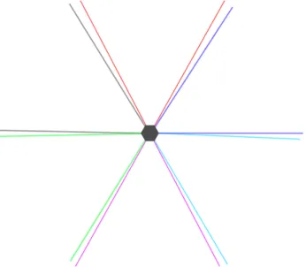
Figure 1: Top-down view of six cameras in a hexagonal setup. The cameras’ field of view are color-coded
for easier reference. Blind spots are inevitable with six cameras, each with a field of view of 57◦.
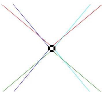
Figure 2: Top-down view of four cameras in a square setup with zoom lenses attached. The cameras’
field of view are color-coded for easier reference. The overlap eliminates blind spots in the working area of the sensors.
As mentioned previously, the Nyko Zoom lens affects both the cameras field of view and ability to find and track people. With the decreased ability to find people at the edges of the field of view, a larger overlap is required between cameras. Luckily, the benefit of a wider field of view still outweighs the increased overlap, resulting in a total increase in field of view. However, while the camera is able to find people around the edges, its ability to do so is noticeably decreased. All in all, the Zoom lens allows us to reduce the number of required cameras needed to cover 360◦, since the field of view of each camera, with the help of the Zoom lens, is increased to the vicinity of 95◦. This proved to be essential with respect to performance.
3.2.3 Performance
With more than one sensor connected and running simultaneously, processing the provided data starts becoming more and more computationally heavy. In particular, projecting a depth image onto a user interface and people tracking were the largest performance sinks. Since the end product has little need to display information for users to see, depth frame processing and projection could be disabled along with anything else related to presenting information mostly used for development purposes. However, even with only the skeleton stream alone, two sensors operated with lower than acceptable frame rates (on an Intel Core 2 Duo 2.2 GHz processor) while in the event driven mode. Switching to polling mode provided a surprising boost to performance and also offered easier parallelization (frame rates increased from around 20 to stable at the cap of 30 frames per second). Work is distributed among threads, one for each sensor and each stream. In other words, there are three threads for each sensor if the color stream and depth stream are enabled, otherwise there is only one for the skeleton stream. In comparison between running all three streams (color, depth and skeleton) and only the skeleton from two sensors on two different machines, it became clear that more than two sensors could pose a real problem with regards to performance. The first test computer (Intel Core 2 Duo 2.2 GHz) had just enough processing power to be able to run two sensors with all three streams enabled, while the second test computer (Intel Core i5 2500k 3.3 GHz) were able to run the same setup flawlessly.
When running a Kinect sensor on a PC via USB ports, only one sensor is able to operate on any one USB controller. This stems from the limited bandwidth on the USB 2.0 port [36] (there is only enough bandwidth for one sensor; USB 2.0 port data rate: up to 480Mbit/s [29]). When
connected, Kinect asks the USB controller for the maximum amount of bandwidth it needs to operate. The specification states that this is at least 50% of a USB 2.0 port [36]. If Kinect is not allocated the bandwidth asked for, the device is rejected registration entirely; even though it is possible to operate well under the maximum bandwidth (i.e., by not running all three data streams). Trying to connect the sensor to a USB 3.0 controller instead (USB 3.0 port data rate up to 5 Gbit/s [30]) does not solve the issue, since it seems the version of Kinect used only support USB 2.0, and therefore enables backwards compatibility and operated as if connected to a USB 2.0 controller [35]. Most standard issue motherboards have only two USB controllers. Therefore, for the machine available during this project, supplementary PCI and (or) PCI-e USB controller cards were needed to house the additional Kinect sensors. The machine used had two USB controllers available on the mother board and two additional USB controller cards, 16 GBs RAM and an Intel quad core i7-4770k at 3.5GHz.
3.2.4 Combining the data
Kinect SDK automatically provides player information for people being tracked. Information that can be used to identify a player, for instance a player id number, are generated when a person is found and tracking of that person commences. Since one Kinect is only aware of its own world, and there is no built-in support for using more than one together, these methods of identification can not be merged with another cameras. In other words, there is no way to know if a person A, tracked by camera C1, is the same person as a person B, tracked by a camera C2, just from looking at the provided information. For our purposes, we want one person to represent only one player within the game world, where that player has one role assigned to him/her. Therefore, we need a method of identifying whether a new person P entering any cameras field of view is actually a new, and unique, player or if that person is an already existing player that has transitioned from some other camera. While potentially achievable through analyzing the depth frames and performing a second people identification computation, a simpler way is to identify players based on their positions in the world. It turns out that this method is accurate enough for our purposes.
3.2.4.1 Fixed camera model and transformations All world information provided by a Kinect is relative to its own world space. That is, any information about where a player is located, or where a joint of that player is located, is in the coordinate space of the camera. In this coordinate space, from the point of view of the camera, the x-axis is horizontal, the y-axis is vertical and the z-axis is depth or distance from the camera. As an example, a player’s position might be given by Kinect as (0, 0.5, 1.8). From this vector we know that the player is positioned on the line drawn perpendicular to the camera. That is, the player is standing exactly in the middle of the cameras point of view on the horizontal axis. We also know that the player is positioned a positive 0.5 meters from the x-axis along the vertical axis and at a distance of 1.8 meters from the camera, see figure 3.
As we know, Kinect is only aware of its own world. As such, if we were to place two cameras such that they are able to track the same person simultaneously, but not have them placed in the same location, the two cameras would of course provide two completely different position vectors for the same person. In order to combine player data from all cameras and for that data to remain meaningful, the position vectors from each camera must be transformed to a world coordinate space. In this case, one camera acts as the main camera and the other cameras position vectors are transformed to fit into the coordinate space of the main camera.
For the purpose of this project, a fixed camera model is acceptable. While it may be feasible and accurate enough to dynamically calculate the offset in position between the cameras (in the real world) by utilizing some reference object, a simpler approach is to use a fixed model. From a fixed camera model, we can measure the distances between the cameras, as well as difference in rotation, and apply transformations to the position vectors provided for players to combine
Figure 3: An example of a person at (0, 0.5, 1.8). The grey line indicates the camera’s point of origin.
The positive 0.5 meters in the vertical axis stems from the center of the body of the person relative to the camera’s point of origin. When people move closer or further away from the camera, this value is changing due to the perspective.
position data from all cameras in one world space. These transformations are calculated by utilizing linear algebra and transformation matrices for translation and rotation. In short, this means that the position vectors provided by the cameras are multiplied by a translation matrix, for the shift in position, and a rotation matrix for the shift in rotation. The differences in position and rotation, in the real world, between each camera and the main camera are provided as input to these matrices, described as follows:
Tθp(θ) = cosθ 0 sinθ 0 1 0 −sinθ 0 cosθ px py pz = cosθpx+ sinθpz py cosθpz− sinθpx
The resulting vectors are meaningful within the world coordinate space (or the main camera coordinate space) with the origin in the real world position of the main camera. In fact, because of how the cameras must be positioned, a point of origin slightly behind the main camera makes more sense, as described in figure 4.
Figure 4: Top-down view of a six camera and a four camera setup. The origin of the world coordinate
space, which each camera is transformed to, is denoted by the red circle.
3.2.4.2 Parallelism As discussed previously, performance has been a major culprit through-out the project. Running four or more Kinect sensors in a non parallel fashion would most likely be impossible. Of course, parallel computing brings a multitude of its own problems to the ta-ble. In this case, four (or more) sensors cooperate in updating positions (and other information, further discussed in the next section) of all participating players in one world space. In other words, there are multiple threads manipulating a single data source. In particular, there is a separate thread for each data stream for each sensor. That is, for some sensor, there is a thread for the RGB stream, another for the depth stream, and finally a third for the skeleton stream. This introduces problems common in parallel systems, such as race conditions. In short, a race condition is what can occur when multiple threads are unsafely reading or manipulating the same data. With unfortunate timing, one of the threads can read or manipulate data in an order not intended by the programmer. To prevent these problems, the shared data source is locked by the sensor threads for the critical sections, preventing other threads from accesses the data until it is unlocked. While preventing race conditions was not entirely necessary for the basics of the application (mainly the positions of players), it is vital to the features discussed in the next chapter (recognizing what players are doing). The reason for this is that incorrect information from a few updates to the positions would at the worst display peculiar behaviour in the user interface, such as a person appearing to be in a place where he or she is not. However, since the frame rate is fairly high (30 frames per second), this is hardly noticable by users. In the next chapter, we discuss how we approached gathering more information about the players and why it proved to be imperative to have locks on critical sections.
3.3 Recognizing gestures and specific movement
The next step is extracting information about what active players are doing. This section will describe the processes involved in finding this information, starting with player identification and why it is important to know who is doing what. We will then discuss the gesture recognition itself.
3.3.1 Identification
For the purpose of this project, it is important to keep track of unique players. Recall that each Kinect sensor is only aware of its own world and player id:s. If player A transitions from camera
C1 to camera C2 there is no way for C2 to know that this is the same player that were just present in C1:s world. In fact, during the transition, when both C1 and C2 are tracking player
A, there is still no way for the cameras to know they are tracking the same player. For just the
position based system, this was entirely acceptable. However, in order to assign roles to players and allow them to keep their role through camera transitions, we need a means of identifying these players.
First, we introduce an active player vector to house information about all currently active players in the world space. When a player is detected by a camera, a new player is added to this vector along with an identification number and current position (the position is of course also continuously updated). The aim is for a player A to be able to freely transition between cameras and always remain identified as player A. As mentioned previously, this identification is based on player positions. Of course, the positions given for player A when he or she is transitioning between C1 and C2 will not be exactly the same in the world coordinates. The cameras suffer from noise (further amplified by the Nyko lens) and the transformations are based on error prone measurements from the real world. Therefore, we approximate the identification by looking at players who are closest to the player we want to identify. In other words, when player A, who is seen and tracked by C1, enters C2 (and C2 creates a new player id for A) we search for the closest active player to the player newly created by C2. Player A is found to be the closest player, within a maximum range of 1 meter, and we determine that the player entering C2 must
be the same player who is also active in C1.
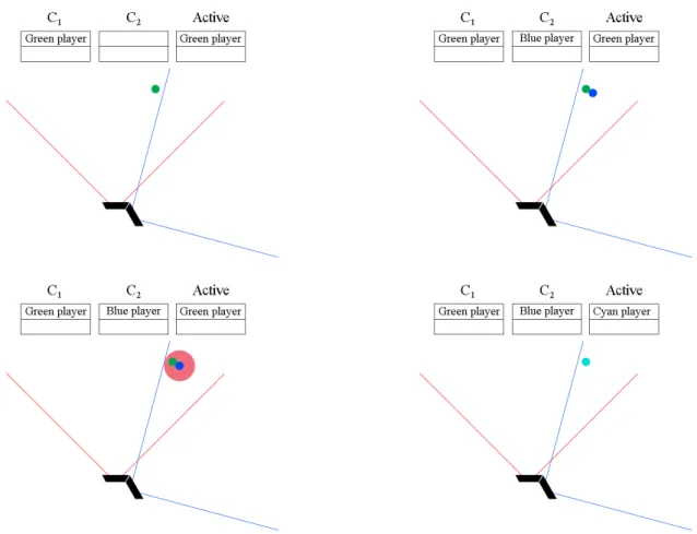
Figure 5: Illustration of a scenario where a player depicted by a green ellipse transitions from C1 (red
field of view) to C2 (blue field of view). The tables show the active tracking for the cameras and the
active player list. In the second image, green is tracked by C1, and blue is the same player tracked by C2.
The positions are illustrated as slightly different due to possible noise. The third image shows how the range check is performed for the new player. Since green is within the range threshold, the players are merged into one player, called cyan (in fact, the ID of green would be preserved in a merge, we show a different color here for the purpose of illustration. Note that both cameras are still tracking both players and that the active list is an abstraction.
The maximum search distance of 1 meter has proven to be accurate enough that players are correctly identified even if two players make a camera transition close to each other. There is also a possibility that C1 loses vision of A before C2 is able to start tracking A. In this case, there would be no active player to search for as A enters C2; player A has already been removed from the active players vector when he or she left C1. To solve this, there is a configurable time delay before any player is removed after leaving a camera’s vision and not identified by some other camera. This delay can safely be set to a few seconds to ensure that players are not accidentally dropped during transitions or when they are briefly blocked by other players or objects. As previously discussed, the identification process and active players vector model are heavily dependant on thread safety. Without locks on critical sections, situations can arise where a thread is trying to manipulate a player that has already been removed from the active players vector, causing an exception and in some cases unintended behaviour.
3.3.2 Gesture recognition
Kinect SDK does not have built-in support for gesture recognition. For our purposes, a third party library providing support for recognizing common gestures and the ability to add custom
gestures is desirable. [31] is an open source Kinect gesture recognition library that recognizes gestures by examining a set of consecutive segments, which together are interpreted as a gesture. That is, a gesture is composed of a series of skeleton pose snapshots which, if recognized in the correct order, is interpreted as a complete gesture. For example, the gesture of raising your left arm is only one frame checking that the player’s left elbow is above the left shoulder, the left hand is above the left elbow and the right hand is not also raised in a similar fashion (in order to not confuse this gesture with both arms raised). The wave gesture consists of several frames to be able to recognize that the hand and arm are moving back and forth a few times. The Fizbin library allows for easy implementation of simple gestures (like arms raised) but it proved to be time consuming and difficult to convert a more complex gesture into a set of specific frames while keeping a natural feel in performing the gesture. This approach is also not ideal for implementing gestures that are more vague, such as simply walking past a camera’s field of view. While easy to recognize, this gesture would constantly be falsely recognized even while players are perfoming other gestures. In general, “full body” gestures, such as jumping, walking between two points or crouching, is difficult to realise using this approach. This is because other gestures can be divided into poses where joints are in certain positions relative to other joints, while in the case of jumping the entire body is moving without a reference point. It is not possible to only examine the height coordinate information to see if a person is jumping; the camera perspective causes the height to change simply when a player approaches or walks away from the camera. Our solution can successfully detect gestures which has some point of reference by using the Fizbin library and defining a gesture as a series of poses executed in a specific order within some time frame. However, it can not accurately detect full body gestures.
4
Results
This section presents the prototype system and its performance. First we look at the user interface to get an overview of the application and the data provided there. We then look at the results of attempting to cover a wide area with an array of sensors, followed by the adding of gesture recognition in a wide area. Finally, we look at some performance test data.
4.1 User interface
As described earlier, the user interface is not a necessary part of the application with regards to its goal functionality. However, as a debugging and monitoring tool it is invaluable. The user interface is capable of displaying information about the sensors such as RGB camera feed, depth camera feed, frames per second and milliseconds per frame for a chosen data stream, distance to tracked players and an overview of the tracked area. The overview shows the combined world coordinate space with active players as indexed circles as they move around the area. Each camera and its respective field of view is color-coded. Figure 6 shows the overview user interface.
Figure 6: User interface showing an overview of the combined world coordinate space of all cameras.
Players are shown as indexed circles, with color-coded cameras and field of view indicators.
In Figure 6, the overview shows two active players, indexed 1 and 2. Player 2 is tracked by the red camera (indexed 0 in the status text), while player 1 is tracked by both the red and yellow cameras (indexed 0 and 1). The status text also shows player position coordinates and tracking id numbers.
4.2 Tracking with an array of sensors
Using the methods described previously to perform identification of players between cameras, the final system is able to track multiple people in a wide area accurate enough for its purposes. These people were able to move between cameras while being continuously tracked by the system. It was also possible for people to be close to each other (within 0.3 meters) without confusing the
system into interpreting two people as one and the same. Occasionally, the system loses track of people during camera transition or when something briefly blocks the line of sight between the camera and a person. These small windows of noise are acceptable and the tracking adequately fulfills the first part of the problem statement.
The system has been tested by having up to four people simultaneously in the working area of the sensor array (360◦ during testing). That is, four testers have been moving freely in and out of the tracked area without any instructions limiting their choices of movement.
As a side note, after the conclusion of this project, and after some changes, the system has been operating successfully in a museum. These changes are however related to the gesture recognition, and not the work presented in this thesis.
4.3 Gesture recognition
While the final system is successful in recognizing some simple gestures performed by different players, it fails to correctly identify which player performed a specific gesture. This problem largely stems from the difficulties of adding a layer of abstraction on top of the local skeleton data of each sensor. In other words, comparing skeletons between cameras is troublesome and the identification process needs improvements in order to satisfactorily solve the problem of recognizing gestures as described in the problem statement. Indirectly, this means that the sensor array does not “operate as one” sensor as described by one of the initial goals. While seemingly possible to accomplish, this is not actualized by the final system. Therefore, the second part of the problem statement is not fulfilled.
4.4 Performance testing
Since there is no hardware setup designed for the purpose of running four to six Kinect sensors in parallel in one program, it is interesting to examine the performance of the proposed system setup. The tests have been performed on an Intel quad core i7-4770k at 3.5GHz, 16GBs RAM and four PCI-e USB controller cards. Tests range from one to four Kinect sensors connected, each to its own separate PCI-e USB controller card. Each test has been performed with 0, 1 and 2 people tracked by connected sensors. The duration of the tests are roughly 5 minutes. For the tests where a person is being tracked, a person has entered the tracking area roughly 30 seconds into the tests, and left at roughly 30 seconds remaining. For the two person tests, the second person has entered and left roughly 10 seconds after the first person. The idea is to see if we can observe a change in performance depending on the number of people being tracked.
We look at memory usage, cpu time, frame time for every frame for each data stream, and frames per second (inferred from frame time; included since it may be a more intuitive measurement for some). Frame times and FPS are stored each time a frame is available for each of the data streams, while memory usage and cpu time are stored as snap shots each time sensor 0 (the first sensor) receives an RGB frame. Since the data has been captured for each data stream independently, there is no time correlation between data stream measurements. Along the x-axis, we simply show frame count (numbers are shown in magnitude x · 102) recorded as they were available. In other words, the total amount of frames may (and will indeed) differ from two types of data streams. Also, since there is no time correlation between the stream types, it is not possible to accurately see the state of all streams for some point in time. However, this representation shows that some streams can produce significantly fewer total frames (which is of course also the stream with the longest frame time on average). For brevity, we only include a subset of all tests in detail, while for some tests, performance data has been averaged over the three data streams.
0 5 10 15 20 25 30 35 40 45 50 55 60 65 70 75 80 85 90 95 0 10 20 30 40 50 60 70 80 Frame count sensor 0 RGB Depth Skeleton
Figure 7: Frame times (in ms) from testing with 0 persons and 1 sensor for RGB, depth, and skeleton
frames. The frame count are shown in magnitude x · 102and were recorded as they became available.
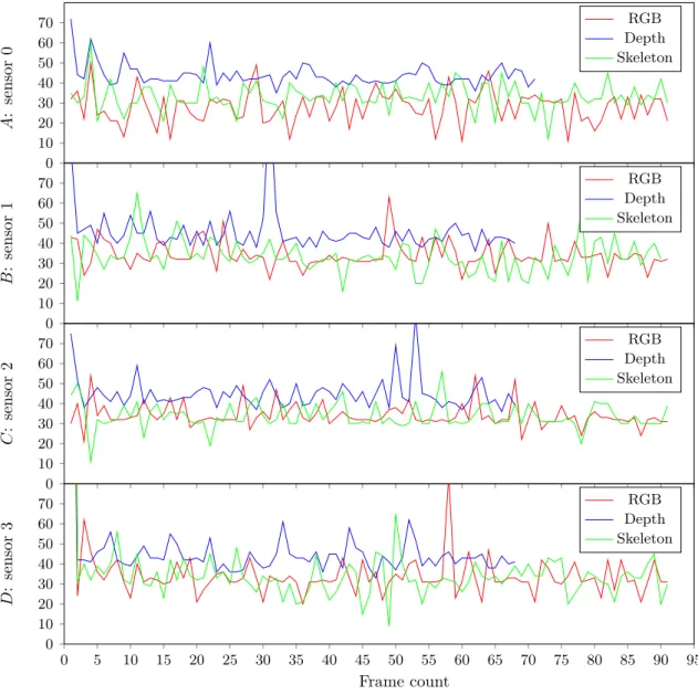
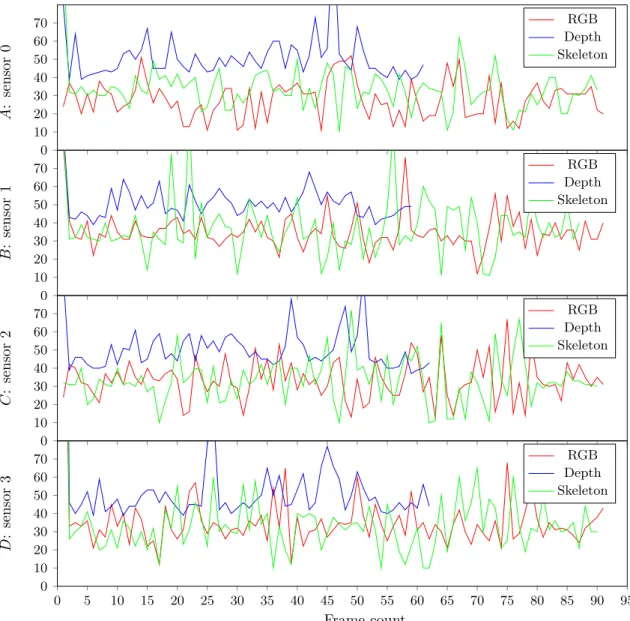
0 10 20 30 40 50 60 70 A : sensor 0 RGB Depth Skeleton 0 10 20 30 40 50 60 70 B : sensor 1 RGB Depth Skeleton 0 10 20 30 40 50 60 70 C : sensor 2 RGB Depth Skeleton 0 5 10 15 20 25 30 35 40 45 50 55 60 65 70 75 80 85 90 95 0 10 20 30 40 50 60 70 Frame count D : sensor 3 RGB Depth Skeleton
Figure 8: Frame times (in ms) from testing with 0 persons and 4 sensor for RGB, depth, and skeleton
frames. The frame count are shown in magnitude x · 102 and were recorded as they became available.
The four above figures A, B, C and D shows the performance of sensors 0, 1, 2 and 3, respectively, as all four sensors have been running simultaneously.
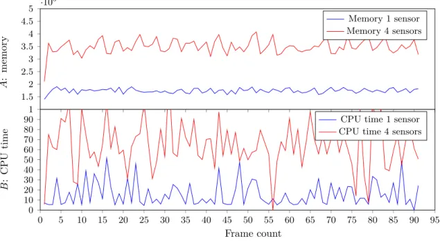
1 1.5 2 2.5 3 3.5 4 4.5 5 ·10 5 A : memory Memory 1 sensor Memory 4 sensors 0 5 10 15 20 25 30 35 40 45 50 55 60 65 70 75 80 85 90 95 0 10 20 30 40 50 60 70 80 90 Frame count B : CPU time
CPU time 1 sensor CPU time 4 sensors
Figure 9: Memory usage (in KB) and CPU time % for 0 persons, 1 and 4 sensors. The frame count are
shown in magnitude x · 102 and were recorded as they became available. Plots A and B shows memory
usage and CPU time, respectively.
0 5 10 15 20 25 30 35 40 45 50 55 60 65 70 75 80 85 90 95 0 10 20 30 40 50 60 70 80 Frame count sensor 0 RGB Depth Skeleton
Figure 10: Frame times (in ms) from testing with 2 persons and 1 sensor for RGB, depth, and skeleton
frames. The frame count are shown in magnitude x · 102and were recorded as they became available.
0 10 20 30 40 50 60 70 A : sensor 0 RGB Depth Skeleton 0 10 20 30 40 50 60 70 B : sensor 1 RGB Depth Skeleton 0 10 20 30 40 50 60 70 C : sensor 2 RGB Depth Skeleton 0 5 10 15 20 25 30 35 40 45 50 55 60 65 70 75 80 85 90 95 0 10 20 30 40 50 60 70 Frame count D : sensor 3 RGB Depth Skeleton
Figure 11: Frame times (in ms) from testing with 2 persons and 4 sensor for RGB, depth, and skeleton
frames. The frame count are shown in magnitude x · 102 and were recorded as they became available.
The four above figures A, B, C and D shows the performance of sensors 0, 1, 2 and 3, respectively, as all four sensors have been running simultaneously.
1 1.5 2 2.5 3 3.5 4 4.5 5 ·10 5 A : memory Memory 1 sensor Memory 4 sensors 0 5 10 15 20 25 30 35 40 45 50 55 60 65 70 75 80 85 90 95 0 10 20 30 40 50 60 70 80 90 Frame count B : CPU time
CPU time 1 sensor CPU time 4 sensors
Figure 12: Memory usage (in KB) and CPU time % for 2 persons, 1 and 4 sensors. The frame count are
shown in magnitude x · 102 and were recorded as they became available. Plots A and B shows memory
usage and CPU time, respectively.
01S 02S 04S 11S 12S 14S 21S 22S 24S 30 35 40 45 50 F rame time (in ms)
Color Depth Skeleton
Figure 13: Frame times (in ms) for tests XYS, where X is the number of persons and Y is the number of
sensors. For each test case, the plots show average frame time for the color, depth, and skeleton frames.
01S 02S 04S 11S 12S 14S 21S 22S 24S 18 20 22 24 26 28 30 32 34 36 F rame rate (in frame s p er second)
Color Depth Skeleton
Figure 14: Frame rate (in frames per second) for tests XYS, where X is the number of persons and Y
is the number of sensors. For each test case, the plots show average frame rate for the color, depth, and skeleton frames. 01S 02S 04S 11S 12S 14S 21S 22S 24S 1.5 2 2.5 3 3.5 ·105 Memory usage (in KB) Memory
Figure 15: Memory usage (in KB) for tests XYS, where X is the number of persons and Y is the number
of sensors. For each test case, the plots show average memory usage of the system during testing.
01S 02S 04S 11S 12S 14S 21S 22S 24S 10 20 30 40 50 60 70 80 CPU time (in %) CPU time
Figure 16: CPU time (in %) for tests XYS, where X is the number of persons and Y is the number of
sensors. For each test case, the plots show average CPU time usage of the system during testing.
It may seem peculiar that the CPU time measurements jump in such a erratic fashion. Since it changes so frequently, and since the data given from the operating system may not be accurate on such small time intervals, it may be more useful to imagine an averaged plot for CPU time instead. In fact, observing the operating system resource monitor (which updates more seldom) during testing, the CPU time stayed at a more constant level.
4.4.1 Test results
One of the first obvious results are the differences in CPU time and memory usage as the number of sensors increases. Test data shows increasing memory and CPU time values as the number of sensors increased from 1 to 4, see Figure 15 and Figure 16. We can also observe a slight increase in memory and CPU usage as the number of persons being tracked increases. The scaling in memory and CPU time is close to linear when adding more sensor after the first. That is, the memory usage of around 150,000 KBs does not increase to 300,000 KBs when the number of sensor double from 1 to 2. Instead, memory usage increases by between 30,000 and 50,000 KBs per additional sensor up to 4 sensors. Similar behaviour can be observed for the CPU time. However, the increases are greater as the number of sensor increases after the first (from 1 sensor at ∼15% CPU time to ∼70–80% at 4 sensors). This may indicate that the limit for this system lies around 5-6 sensors.
Examining the 4 sensor tests for 0 persons and 2 persons, we can clearly observe a difference in frame time performance from 0 persons to when 2 persons are being tracked. While the average frame time is similar, the frame times are certainly spiking more. We can also observe a noticeable difference in total frames produced for the depth stream. At 0 persons, the depth stream produced about 6800 frames, while at 2 persons it produced roughly 6200.
Increasing the number of sensors from 1 to 4 severely impacts the frame time of the depth stream. Frame time increases from about ∼30ms to ∼45ms at 4 sensors, reducing the total
number of frames produced by over 2000. Although this may seem worrying, recall that the depth stream is not a necessity for the purposes of the system. Therefore, these results are not cause for alarm.
Overall, the test results indicate that the system should have enough resources to run 5 or 6 sensors and thus be able to cover 360◦ without the use of any lens. As a side note, the system has been operational with 6 sensors and up to 20 people and was observed as running without issues.
5
Conclusions
In this thesis we have described a system which allows for tracking and uniquely identifying people in a wide area by using an array of Kinect sensors. While the initial goal of the project may not have been fully realised, the contribution is insight into the challenges of making multiple cameras work together as one. Mainly, performance and computational power is a huge factor when running multiple sensors on a single computer. Since Kinect lacks support for synchronization between sensors, parallelization and abstraction has been required, introducing further challenges. Moreover, we have provided insight into the difficulties of correctly identifying whether newly detected people are already being tracked by another camera. We have also discussed possible alternative solutions to these problems. It is entirely possible that these limitations and challenges are unique to the chosen type of hardware and software. Building a similar system using a sensor other than Microsoft Kinect and software other than Kinect SDK, many of these problem may easily be resolved and a new set of challenges may present themselves. Finally, we have provided performance data for various tests, indicating the requirements of a multiple sensor system and where there are possible limits on hardware resources for a single computer.
5.1 Future work
5.1.1 Camera model
The current camera model requires the cameras to be set up in a fixed and precise way to ensure that transformations between cameras are computed correctly. Done manually, or even with the help of a platform or rig built to ensure correct camera placement, this is error prone and forces a specific field of view. A possible improvement is to let the system calculate the differences in position and rotation of the cameras based on some reference points. Kinect sensors are accurate from a few millimeters to about 4cm [32]; it is difficult to speculate if this would overall be more or less accurate than the current solution. In any case, this improvement would allow an arbitrary camera setup, as long as the interference between cameras are respected.
5.1.2 Identification
Since we are given local player id numbers from each camera, it may seem crude to identify players based on position in the combined world space. With no support for comparing two players to see if they are one and the same, and without people recognition support, it is only possible to examine players joint information (such as height or position). By performing a second people detection computation (such as facial recognition) aiming towards identifying unique players, it may be possible to achieve a more accurate identification method. Kinect 2.0 ships with support for facial tracking, providing shape information for many features of the face (such as nose, eyebrows and chin) [37]. This feature should certainly be able to distinguish between different people, solving the identification problem in an alternative way. However, identification by facial recognition fails when peoples faces are not visible, i.e., when people are facing away from the camera.
5.1.3 Gesture recognition
There is certainly room for improvement regarding the gesture recognition. There are countless games available for Kinect that supports a wide array of different gestures. Improving in this area is certainly a possibility, albeit time consuming and complex. We would like to see support for less common gestures or ways of interacting with the system; more commonly seen in the target environment and able to surprise the audience. An example discussed previously: a person simply walking by.
5.1.4 Performance
Most of the challenges within this project has been related to performance. Not only is a fast computer required to run four or more Kinect sensors, additional USB controller hardware is needed. During testing there has been indications that the USB controllers connected through a PCI slot suffers from performance losses in comparison to those connected via PCI-e slots. An interesting alternative to running all sensors on one computer is a network based solution. Con-sidering the type of motherboard required to house four USB controllers (the two motherboard controllers and two PCI-e slots), a network based solution using smaller size computers might be more compact than using a single computer.
References
[1] D. Beymer and K. Konolige, Real-Time Tracking of Multiple People Using Continuous
De-tection. Artificial Intelligence Center SRI International Menlo Park, CA 94025 (ACL).
[2] I. Haritaoglu, A Real Time System for Detection and Tracking of People and Recognizing
Their Activities. Computer Vision Laboratory University of Maryland.
[3] R. Lange and P. Seitz, Solid-State Time-of-Flight Range Camera. in IEEE Journal of quan-tum electronics, vol. 37, NO. 3, March 2001.
[4] V. Ganapathi, C. Plagemann, D. Koller and S. Thrun, Real Time Motion Capture Using a
Single Time-Of-Flight Camera. Stanford University, Computer Science Department,
Stan-ford, CA, USA.
[5] J. Zhu, L. Wang, R. Yang and J. Davis, Fusion of Time-of-Flight Depth and Stereo for High
Accuracy Depth Maps. Center for Visualization and Virtual Environments, University of
Kentucky, USA. Computer Science Department, University of California, Santa Cruz, USA. [6] S. Ioffe and D.A. Forsyth, Probabilistic Methods for Finding People. Computer Science
Di-vision, University of California at Berkeley, March 12, 2001.
[7] C. Stauffer and W.E.L Grimson, Adaptive background mixture models for real-time tracking. The Artificial Intelligence Laboratory Massachusetts Institute of Technology Cambridge. [8] X. Liu, P. H. Tu, J. Rittscher, A. G. A. Perera and N. Krahnstoever, Detecting and Counting
People in Surveillance Applications. GE Global Research Niskayuna, NY, USA.
[9] S. Ikemura and H. Fujiyoshi, Real-Time Human Detection using Relational Depth Similarity
Features. Dept. of Computer Science, Chubu University.
[10] A. Bhattacharyya, On a measure of divergence between two statistical populations defined
by their probability distributions. Bulletin of the Calcutta Mathematical Society 35: 99–109,
1943.
[11] L. Spinello and K. O. Arras, People Detection in RGB-D Data.
[12] N. Dalal and B. Triggs, Histograms of oriented gradients for human detection. in Proc. of the IEEE Conf. on Comp. Vis.and Pat. Rec. (CVPR), 2005.
[13] G. Rigoll, A. Kosmala and S. Eickeler, High performance real-time gesture recognition using
Hidden Markov Models. Gerhard-Mercator-University Duisburg, Department of Computer
Science, Faculty of Electrical Engineering, Duisburg, Germany.
[14] Y. Jie and X. Yangsheng, Hidden Markov Model for Gesture Recognition. Carnegie-Mellon University, Robotics Institute, Pittsburgh.
[15] E. Kollorz, J. Penne, J. Hornegger and A. Barke, Gesture recognition with a
Time-Of-Flight camera. in International Journal of Intelligent Systems Technologies and Applications,
Volume 5 Issue 3/4, November 2008, Pages 334-343.
[16] Linear Transformation. Wolfram Mathworld, Retrieved from http://mathworld.wolfram. com/LinearTransformation.html, last viewed 18th May 2014.
[17] Translation matrix. Wolfram Mathworld, Retrieved from http://mathworld.wolfram. com/Translation.html, last viewed 18th May 2014.
[18] Rotation matrix. Wolfram Mathworld, Retrieved from http://mathworld.wolfram.com/ RotationMatrix.html, last viewed 18th May 2014.
[19] Human Interface Guidelines. Microsoft Developer Network, Retrieved from http://msdn. microsoft.com/en-us/library/jj663791.aspx, last viewed 18th May 2014.
[20] Kinect technical specifications. Microsoft Developer Network, Retrieved from http://msdn. microsoft.com/en-us/library/jj131033.aspx, last viewed 18th May 2014.
[21] S. Izadi, D. Kim, O. Hilliges, D. Molyneaux, R. Newcombe, P. Kohli, J. Shotton, S. Hodges, D. Freeman, A. Davison and A. Fitzgibbon, KinectFusion: Real-time 3D Reconstruction and
Interaction Using a Moving Depth Camera. Microsoft Research Cambridge, Imperial College
London, Newcastle University, Lancaster University, University of Toronto.
[22] Zoom lens. Nyko, Retrieved from http://www.nyko.com/products/product-detail/ ?name=Zoom, last viewed 18th May 2014.
[23] Silverlight. Microsoft Developer Network, Retrieved from http://msdn.microsoft.com/ library/cc838158(VS.95), last viewed 18th May 2014.
[24] Windows Forms. Microsoft Developer Network, Retrieved from http://msdn.microsoft. com/en-us/library/dd30h2yb(v=vs.110).aspx, last viewed 18th May 2014.
[25] Windows Presentation Foundation. Microsoft Developer Network, Retrieved from http:// msdn.microsoft.com/en-us/library/ms754130(v=vs.110).aspx, last viewed 18th May 2014.
[26] J. Smith, Windows Presentation Foundation or Windows Forms. Blog post, Retrieved from http://joshsmithonwpf.wordpress.com/2007/09/05/wpf-vs-windows-forms/, last viewed 18th May 2014.
[27] Dispatcher Class. Microsoft Developer Network, Retrieved from http://msdn.microsoft. com/en-us/library/vstudio/system.windows.threading.dispatcher, last viewed 18th May 2014.
[28] C. Schönauer and H. Kaufmann, Wide Area Motion Tracking Using Consumer Hardware. Interactive Media Systems Group, Institute of Software Technology and Interactive Systems, Vienna University of Technology, Austria.
[29] Compaq, Hewlett-Packard, Intel, Lucent, Microsoft, NEC and Philips, Universal Serial Bus
Specification. Revision 2.0, April 27, 2000, Retrieved from http://sdphca.ucsd.edu/Lab_
Equip_Manuals/usb_20.pdf, last viewed 18th May 2014.
[30] Hewlett-Packard Company, Intel Corporation, Microsoft Corporation, NEC Corporation, ST-NXP Wireless and Texas Instruments, Universal Serial Bus 3.0 Specification. Revision 1.0, November 12, 2008, Retrieved from http://www.gaw.ru/pdf/interface/usb/USB% 203%200_english.pdf, last viewed 18th May 2014.
[31] Except on Tuesdays (Fizbin) Kinect Gesture Library. Kinect Gesture Library, open source, Retrieved from https://github.com/EvilClosetMonkey/Fizbin.Kinect.Gestures, last viewed 18th May 2014.
[32] K. Khoshelham and S. O. Elberink, Accuracy and Resolution of Kinect Depth Data for
Indoor Mapping Applications. Faculty of Geo-Information Science and Earth Observation,
University of Twente.