Automated Removal of Prepreg Backing Paper
- A Sticky Problem
Andreas Björnsson, Jan Erik Lindbäck and Kerstin Johansen
Linköping University Post Print
N.B.: When citing this work, cite the original article.
Original Publication:
Andreas Björnsson, Jan Erik Lindbäck and Kerstin Johansen, Automated Removal of Prepreg
Backing Paper - A Sticky Problem, 2013, Proceedings of the SAE 2013, Aerotech Congress
and Exhibition, 24th-26th September 2013, Montreal,Canada.
http://dx.doi.org/10.4271/2013-01-2289
Copyright: 1913 SAE International
http://papers.sae.org/
Postprint available at: Linköping University Electronic Press
ABSTRACT
Automated solutions for manufacturing composite products based on prepreg often imply Automatic Fiber Placement or Automatic Tape Laying. These systems are generally associated with huge investments. For certain manufacturing applications it is interesting to investigate alternatives to find simpler and less costly automation. One example of an automated system could be the use of a standard industrial robot to pick single prepreg plies from an automated cutting machine and stack them to form a plane laminate. This paper is based on a case illustrating a product from the aircraft manufacturing industry. The case will demonstrate a pick and place concept on a general level and illustrate challenges that must be solved. The challenge selected to be the main focus for this paper is an automated process for backing paper removal. A literature review of different gripping technologies reveals several interesting technologies, and the most promising are tested for backing paper removal. The tests show that an automated removal process can be designed by using standard vacuum grippers in combination with mechanical clamping grippers. In order to lift the backing paper with a vacuum gripper an initial separation between the backing paper and prepreg is needed. This separation is most easily mechanically induced by bending the material. The proposed solution for automatic backing paper removal can be integrated in a manufacturing cell for manufacturing of the studied product.
INTRODUCTION
In the strive to reduce fuel consumption by saving weight in aerospace and automotive applications, composite materials present an appealing alternative. Polymer fiber composite materials offer a combination of low weight and high stiffness and strength. An increased use of composite materials contributes to an enhanced need for rational manufacturing methods suitable for manufacturing components in a cost-efficient way. Several automated manufacturing systems for composite products have been developed, but in some manufacturing systems much of the work is still performed manually. Further development of automated manufacturing systems is interesting in order to lower production cost. Automation can also increase the quality by making the manufacturing process more repetitive compared to manual operations.
In this article, automation using a pick and place concept is analyzed in the context of a case from the aircraft manufacturing industry. For this automation concept, the task of automated backing paper removal is identified as one of the key areas where a solution that suits the case application needs to be developed. A general literature review of gripping technologies for flexible materials is performed to identify gripping technologies. An evaluation of the suitability for each gripping technology results in the selection of one technology. Tests show that the selected gripping technology does not work in the intended application unless an additional
Automated Removal of Prepreg Backing Paper
-A Sticky Problem
2013-01-2289
Published
09/17/2013
Andreas Björnsson
Linköping UniversityJan-Erik Lindback
Saab AerostructuresKerstin Johansen
Linköping UniversityCopyright © 2013 SAE International doi:10.4271/2013-01-2289
process for separating backing paper and prepreg is developed. Two different methods for separation are developed and tested, and one method is identified as suitable to use in a system for automated backing paper removal. Then, the gripping and separating processes are combined into a proposed solution. How the proposed solution for automatic backing paper removal could be integrated in an automated pick and place cell is outlined in the context of the case product.
PREPREG MATERIAL AND ITS
PROPERTIES
Prepreg material is pre-impregnated fiber reinforcement that is widely used in high quality and high cost applications. This is largely due to the uniform and high level of material quality and fiber density, but these properties are connected with a relatively high material cost. [1] Prepreg is available in a great selection of combinations of matrixes and reinforcement. In this article, the focus is mainly on unidirectional (UD) carbon fiber reinforcements and thermoset matrixes.
Prepreg material possesses two key properties that affect handling in an automated manufacturing environment, namely rigidity and tack. The rigidity is mainly dependent on the fiber material and reinforcement type [2]. Unidirectional reinforcements are especially sensitive to damage during handling due to the material's anisotropic properties. The stiff and protective backing paper that can be found on UD reinforcement improves the material's rigidity [2]. This can be utilized when handling prepreg automatically. Due to the highly anisotropic properties in UD material, the backing paper should be removed along the fiber orientation in order to reduce the risk of changing the direction of the fibers, or in other ways damaging the prepreg [2].
Prepreg tack can be defined as the ability of two prepreg plies to adhere to one another [3]. The level of tack, or stickiness, also influences the material's adhesiveness to backing paper and to mold surfaces. Tack is necessary in order to provide easy layup, since it keeps the different layers fixed during layup. The level of tack depends on the resin and the fibers, as well as processing conditions during manufacturing of the prepreg and environmental conditions that the material is exposed to [3]. The tack level can be altered by varying any of the four variables [3]. For material used for manual layup the level of tack is relatively flexible, since the operator's flexibility can compensate for tack variations [4]. In automated manufacturing solutions the need to control the tack level increases [4]. In both automatic and manual layup of composite material the layup of the first layer is considered to be the most difficult, since the tool often has a smooth surface that, in some cases, is treated with release agents. One commonly used way of changing the level of tack is to heat the material [5]. Adding heat, however, does not always increase the level of tack. In experiments with three different materials, Crossley et al. [4] show that the three materials'
levels of tack respond quite differently to an increased temperature. Another way to increase the level of tack, and thereby increase the layup reliability, is to treat the mold surface with a tackifier.
COMPOSITE MANUFACTURING
Manual Layup
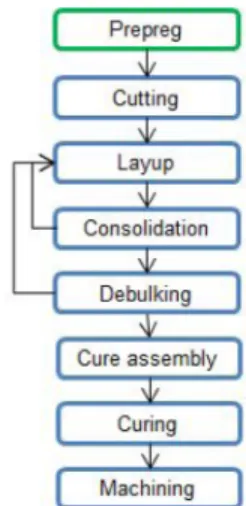
Manual layup of unidirectional prepreg offers flexible manufacturing of composite components. The general manufacturing process consists of the steps shown in Figure 1. The prepreg is taken from the refrigerated storage area in advance to slowly reach room temperature before the cutting process begins. The material, usually protected by backing paper on one side and plastic liner on the other, is unrolled on a cutting table. An automatic cutting system cuts the material to the desired shapes, termed profiles. One or both sides of the prepreg are exposed by removing the plastic liner, and in some cases also the backing paper. The profiles are manually placed on a mold surface or on top of a previously placed layer of prepreg. The operator consolidates each profile by pressing it down to adhere to the mold or previously placed prepreg, often by using simple hand tools.
Figure 1. General working sequence for manual layup.
If the backing paper was left during consolidation it is removed afterwards. More profiles can be laid up and consolidated before the next process step. A debulking process is not necessary for all types of products, but is generally performed for high quality components in order to make sure that all entrapped air is removed [2]. The layup process is repeated until the component has been built up to the required shape. It is prepared for curing during the curing assembly and then cured in a controlled environment in an autoclave. The manufacturing takes place in a clean room and is performed by skilled operators wearing coats and gloves to protect the material. The manufacturing is usually performed in a temperature-controlled environment with temperatures around 20°C. This is not an ideal temperature for the prepreg, but rather chosen for operator comfort [6].
Simple profile shapes that are placed in molds with simple contours can be positioned once and pressed into place with simple hand tools. More complex profile and mold shapes make it difficult to lay down the profile correctly the first time. The profile must, in complex cases, be removed and reattached several times before it is correctly placed. This poses a challenge for automation because once a tacky prepreg material makes contact with a surface, automated removal is not a reliable option [2].
Automated Tape Laying and Automated
Fiber Placement
Automation of the manufacturing process can be a way to increase productivity. The two main automated manufacturing technologies for manufacturing composite components based on prepreg are Automated Tape Laying (ATL) and Automated Fiber Placement (AFP). In ATL systems, a layup head carrying prepreg tape of usually 75 mm, 150 mm or 300 mm width is positioned by a computer-controlled machine, usually built as a horizontal gantry or vertical column type of machine [7].
AFP systems work with much narrower tapes that are typically 3.2 mm, 6.4 mm or 12.7 mm wide [7]. Several tapes can be placed at the same time, and each tape can be individually controlled and cut in an AFP system. According to Lukaszewicz et al. [7], the advantages of ATL systems are high layup rate, a possibility to manufacture large parts, simplified offline machine programming and good mechanical properties in the manufactured components due to the use of prepreg. The disadvantages of the ATL technology are high initial capital investments and limited geometric complexity of the parts produced. Automatic Tape Laying generates higher levels of scrap material compared to Automatic Fiber Placement. AFP systems can be mounted on a robot, which reduces the capital investments compared to the gantry solutions generally applied for ATL systems. The ability to handle several small tapes enables AFP systems to create more complex geometries than are possible with ATL. The productivity is generally lower for AFP systems compared to ATL systems. This is partly due to the fact that they are generally used to manufacture more complex parts. [7]
Automation Using a Pick and Place
Concept
Automated tape laying and automated fiber placement are not applicable for all manufacturing situations. A case study from the aircraft manufacturing industry shows that there are components that cannot be manufactured with ATL or AFP without changing the product design [8]. A change in product design, however, can lead to a renewed product validation, a process that is a costly and time-consuming endeavor [9]. The case study shows that an automated process that utilizes standard automation equipment could be a possible solution, but more research is needed [8]. The use of standard equipment, for instance an industrial robot, to pick cut
profiles and place them in a simple mold is in this article denominated as a pick and place concept.
The case study [8] highlights two areas that need to be developed further. One area that needs to be explored further is the development of a gripping tool that can handle varying geometries of tacky prepreg material. Another area that needs further research is the automatic removal of backing paper after the prepreg profile is placed in the mold. An automated removal process for backing paper is the main focus for this article.
Previous research projects have solved automated backing paper removal in different ways. One solution that has been proposed in the ARMATURE project [10] and in a UK patent [11] is to quickly cool the profile by using cooling spray. Cooling the prepreg has, in our basic tests with two types of aerospace-graded prepreg material, been shown to reduce the tack to a level where the bond between the backing paper and prepreg is very weak. This greatly simplifies an automated removal process; however, the use of cooling spray is not applicable in the solution proposed by Lindbäck et al. [8], since forced cooling brings about a risk for condensation. The risk of moisture being introduced in the manufactured component is unacceptable for the case component.
Buckingham and Newell [2] describe a manufacturing system where the backing paper is removed for inspection and then once more attached to the prepreg in an automatic inspection station. The prepreg with the reattached backing paper is then cut and automatically placed in a mold where it is consolidated. After the consolidation a needle gripper is used to remove the backing paper [2]. Our initial tests with two types of aircraft manufacturing-graded prepreg show that for the tested materials, reattached backing paper forms a much weaker bond to the prepreg than it does before removal. The weaker bond simplifies automatic removal, but the additional rerolling process that is required adds an extra, unwanted, operation.
The Manufacturing of Aircraft Beams
The case that forms the context to this article is automated manufacturing of beams for an aircraft structure. The manufacturing is today done manually. The geometry of the studied component inhibits an automated solution using ATL or AFP without changing the product design, thereby requiring a renewed product validation. The beam consists of four layers. The prepregs are cut in an automated cutting machine and manually stacked on top of each other in a plane stacking sequence. The four-layer stack is then formed in a separate forming sequence. The automatic solution proposed to replace today's manual layup is outlined in Figure 2. The automated manufacturing cell includes a standard cutting machine for cutting the profiles, and a standard industrial robot that lifts and moves the profiles to a vacuum table that holds the flat laminates during layup. The proposed cell is intended to hold four separate laminates in order to reduce the
dependency of manual intervention on the process. The material to be used is aircraft-grade prepreg of ATL format, 300 mm wide and protected by backing paper on one side. The size and shape of the individual profiles varies. The profile that is cut to align with the fiber orientation, 0 direction, is as long as the full length of the laminate, but all the other profiles can be included in the size outlined in Figure 3. The large 0 profile is not included in the automation solution. The separate forming process is also excluded from the automated cell.
Figure 2. Proposed outline of an automated manufacturing cell.
Figure 3. Maximum size of profiles.
The prepreg is, in the proposed manufacturing cell, presumed to be cut with the backing paper upward. It is also presumed that the lifting tool is utilizing vacuum grippers that are in contact with the backing paper during lifting and manipulation. The lifting tool is also able to place the profile onto the vacuum table and consolidate it to the previously placed material. For the first layer of profiles the material is held in place by the vacuum table.
GRIPPING TECHNOLOGY FOR
FLEXIBLE MATERIALS
Lindbäck et al. [8] outline two areas of interest for further research when designing an automated manufacturing cell: gripping of material and removal of backing paper. Both of these areas require fundamental knowledge of commonly used gripping technologies. Therefore, a literature review has been performed in the area of gripping of flexible materials such as paper, textile and composite fabrics. The findings
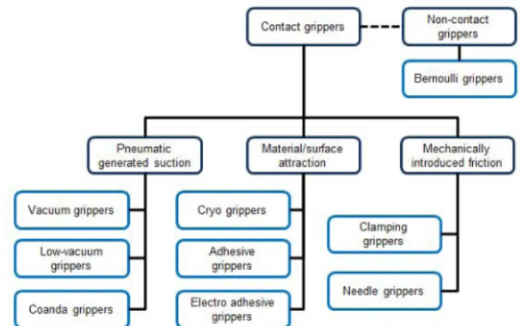
from the review are summarized below and an overview of the examined gripping technologies is given in Figure 4. Following the summary, the technologies are evaluated based on their suitability for use in backing paper removal.
Figure 4. Overview of gripping technologies.
Gripping Technologies Based on
Pneumatically Generated Suction
Vacuum grippers are commonly used in automation solutions for material handling, and there is a wide variety of designs to choose from. The gripper type can be seen as a simple solution for gripping applications, but is associated with certain complications. Standard systems are designed for large underpressure and low airflows [12]. This poses a problem when handling porous materials. One solution is to use high airflow systems. According to Lien and Davis, this type of system calls for the use of large tubes and automatic valves, which in turn generate bulky and complex systems [12]. Angerer et al. [13] categorize the solution with high airflows and low underpressure as low vacuum systems and show examples of successfully developing the technique for the handling of flexible materials [13]. Another problem when using ordinary vacuum systems for handling flexible materials is that the material can be sucked into the vacuum cup, thereby damaging the material [14].
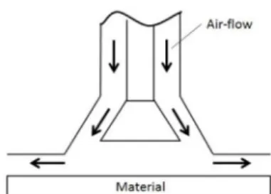
Figure 5. Principle of a Coanda gripper.
Grippers based on the Coanda effect use a small, primary, airflow guided through a nozzle to create a larger, secondary, airflow [12]. The principle is illustrated in Figure 5. The large secondary airflow makes the gripper type suitable to use for handling porous materials. Tests show that there is little risk
of leaving marks when handling material such as textile fibers [12].
Gripping Technologies Based on
Mechanically-Introduced Friction
Mechanical grippers are common in automation solutions and are found in a great variety of designs. Usually they utilize a clamping action that introduces friction forces between the gripper and the object to be handled. The clamping solution generally requires two sides of the object to be accessible, but pinching grippers that can lift limp material with access from only one side also exist [14]. One advantage with clamping or pinching grippers is that the material is easy to remove after the manipulation is finished, as the gripper is simply opened. Needle grippers can be based on straight or curved needles that penetrate the material to be lifted. The penetration depth and angle are usually adaptable and can be adjusted to lift various textile materials [15]. There is an apparent risk to damage sensitive materials, such as composite reinforcements, when using needle grippers. This has been investigated and no reduction of structural integrity was registered, even under unrealistically high testing forces [2]. Despite these results, the recommendation is to grip in surplus material when using a needle gripper in composite handling [2]. The risk of fiber movement during gripping can lead to reduced placement precision [2].
Gripping Technologies Based on
Material or Surface Attraction
The cryogenic gripping technology freezes moisture, usually water, which is sprayed on a surface by placing a cool gripper surface in direct contact with the material. The ice forms an efficient bond between the material and the gripper. The lifted material is released by heating the gripper or by forcing air in-between the gripper surface and the material which results in a faster release [14, 15].The theoretical freezing time for lifting material is around 3 seconds for the gripper constructed by Stephan and Seliger, but shorter times give sufficient lifting forces in many cases [15]. The advantages with the technology are that it does not damage the material surface and that it is a reliable lifting technology [15]. The long pickup times that are required in order to freeze the moisture can be unacceptable in certain automation solutions [14].
Adhesive grippers are based on some sort of adhesive surface that is put in contact with the material to be lifted and forms a bond to the surface. The adhesive surface generally degrades and must be continuously replaced, which generates a consumable cost for the gripper, and the adhesiveness is generally not possible to shut off in order to release the lifted material [14]. Reinhart and Straßer [16] suggest that adhesive grippers could be built using nano-structure surfaces, but conclude that the nano-technology is not yet mature enough to utilize in a manufacturing environment [16]. Adhesive grippers based on sticky surfaces imply a risk of transferring
decontaminations from the gripper to the material that is manipulated [16, 2, 14].
Electroadhesive grippers are based on electric polarization of the material's structure [14, 17]. The electric polarization can be achieved by applying a high voltage across two interlocking patterns of printed circuit board that are covered with a dielectric film [14]. The outer surface of the film is used as a contact surface between the material and the gripper [14]. To lift a material, a high voltage current is applied to the tool. To release the material, the voltage can be turned off, which results in a gradual loss of attraction force, and the release can be aided by an airstream from channels in the gripper [18]. Another method for quick release is to leave the material at an area with higher electroadhesive attraction [17]. The gripping technology is mainly suitable for light textiles, carbon composite fabrics and thin foils. The material that is to be lifted is not damaged by the gripper, since the technology is non-intrusive and the flat gripping surface results in little or no deformation of the material. The systems are based on high voltage levels that can make them complicated to design [17].
Non-Contact Grippers
Bernoulli grippers utilize the underpressure that is produced when an air jet is forced through a narrow slit radial from a nozzle between the nozzle and material. The principle is illustrated in Figure 6. When the nozzle is moved towards the material the repelling force is, at a certain distance, overcome by an attractive force and the material is lifted without contact being established between nozzle and material [19]. Bernoulli grippers have found use in the handling of delicate products such as silicon wafers. Ozcelik et al. [20] have experimented in using Bernoulli grippers to handle flexible materials such as cotton fabric. One immediate experience from their experiments is that the material, since it is not in contact with the gripper, is floating around under the gripper nozzles [20]. Ozcelik et al. [20] report that the team had to place stoppers around the material in order to maintain the material's position during tool movement. For limp materials they noted that small cavities form in the lifted material directly under each nozzle [20].
EVALUATION OF GRIPPING
TECHNOLOGIES
The survey of gripping technologies reveals a number of interesting concepts. Given this, an evaluation based on the assessed suitability of each technology for the intended application of automated backing paper removal was performed. Adhesive grippers are not considered to be suitable since they need continuous replacement of the adhesive contact area, and because the release of lifted material can be complicated. Cryogenic grippers cannot be used since moisture must be avoided in the intended production application, and electroadhesive grippers are deemed to be too complicated. Needle grippers, which are used by Buckingham and Newell [2], are considered to be an interesting solution, but the risk of introducing undesired material, in the form of a broken needle, into the manufactured components is an unacceptable risk. Non-contact grippers, based on the Bernoulli effect, are an interesting group for handling tacky material, but in the context outlined in this article the gripper type is not suitable since a strong lifting force and stable grip is required. The backing paper has a relatively low permeability which makes the use of low-vacuum systems or Coanda grippers unnecessary. The most promising gripping technology to use for backing paper removal is considered to be standard vacuum grippers. The technology is well established and offers a wide variety of gripper designs. Vacuum grippers work in the outlined case where only one side is accessible when the profile has been consolidated and the backing paper is to be removed.
TESTS USING A VACUUM GRIPPER
TO REMOVE BACKING PAPER
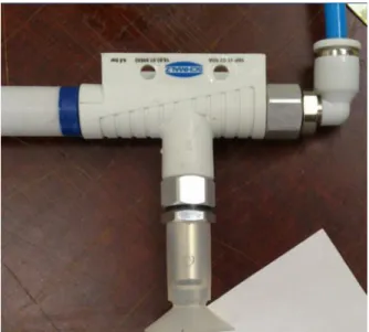
Initial experiments were performed using a standard vacuum gripper and ejector, shown in Figure 7.
Figure 7. Standard vacuum gripper and ejector.
Test samples of aerospace-graded ATL prepreg with an approximate area of 100 × 100 mm were attached to a previously placed layer of prepreg, as shown in Figure 8. The initial test showed that the backing paper did not separate from the prepreg when the vacuum gripper was attached to the paper. The same experiment was then conducted using an industrial vacuum system that generates a much more forceful underpressure, and the same result was attained. When a scalpel was used to manually initiate a separation between the prepreg and the backing paper, the vacuum gripper could pick up the paper and continue the peeling motion to remove the backing paper. The bond between prepreg and a reattached backing paper is so weak that the vacuum gripper can pick up the paper if it is reattached after the initial separation.
This is consistent with observations made by Buckingham and Newell [2] which state that the removal of backing paper can be divided into two parts, peel initiation and peel continuation. They conclude that the peel initiation is the most difficult process [2]. The performed tests show that an initial separation between the paper and the backing paper is necessary in order to pick up the backing paper using a standard vacuum gripper.
Figure 8. Test samples with indicated fiber direction for peel test.
During the peeling, a sliding motion between the paper and the vacuum gripper was observed. The relative sliding between the paper and the vacuum gripper could be a potential problem during peeling. If the vacuum gripper, due to the relative motion, slides off the backing paper before the backing paper is fully removed, the removal will fail. In order to overcome this problem the gripping solution could be designed based on two gripping principles. Firstly, an initial separation of paper and prepreg is performed at one corner of the ply. Thereafter, the paper is picked up using a vacuum gripper. When the paper is picked up both sides become
accessible and can then be gripped using a mechanical clamping gripper. The principle is demonstrated in Figure 9.
Figure 9. A combination of gripping technologies, vacuum and mechanical, can be used for reliable
peeling.
Initial Separation
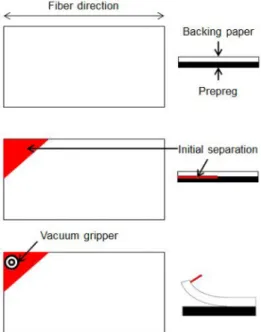
The initial tests show that in order to use a standard vacuum gripper to pick up the backing paper, a separation between the paper and prepreg must be initiated. The tests also show that if the paper and prepreg have been separated and the backing paper is then reattached, it is still possible to lift the paper by using a vacuum gripper. The separation does not have to affect the full profile size. Separation of one corner is enough to allow for a vacuum gripper to lift the backing paper as illustrated in Figure 10. This is true for the prepreg type that is in focus for this article. Simple tests with other prepreg materials show different results, as to be expected since the variation in tack depends on prepreg properties as well as backing paper quality.
Figure 10. One corner of the prepreg and backing paper is exposed to initial separation. Thereafter, a vacuum
gripper lifts the paper.
The initial separation can be generated by several methods. In this article, two separate methods are explored. The first method is a separation aided by injection of compressed air between the prepreg and the backing paper; the second, a controlled mechanical bending that mimics the way an operator manually separates the two layers.
Injected Air
By using an injection needle to punch a small hole in the backing paper, air can be injected between the prepreg and the backing paper. Tests show that this method generates a separation between the paper and the prepreg that is sufficient to then be able to lift the paper using a standard vacuum gripper. The method is however associated with some deficiencies. The compressed air must be clean to not introduce contaminations into the material. There is also a risk of damaging the fibers if the needle is inserted through the paper and into the prepreg. The risk can be reduced by using a foot as a mechanical stop that is put in direct contact with the backing paper. A foot could also be used to guide the airflow in a desired direction. One experience from the empirical tests is that the airflow can take several paths to reach an edge of the material. By pressing on the paper with a foot, the airflow is enclosed in a specific area that is then separated, as illustrated in Figure 11. If the airflow is not controlled to initiate separation in a specific area, the method is not applicable for an automated solution. There is also a small risk of introducing metal into the composite parts if the needle is damaged.
Figure 11. If the airflow is uncontrolled the bubble propagation is unpredictable (left). The process can be made repeatable by controlling the airflow using a foot
(right).
Mechanical Bending
When operators handle prepreg profiles and manually remove the backing paper, two commonly used tricks to establish an initial separation are to flick or bend a corner of the profile. Initial tests show that this action creates enough separation to lift the backing paper with a vacuum gripper. Therefore, an automated alternative has been developed. The automatic solution is based on forced bending around a support, the principle of which is illustrated in Figure 12. A corner of the prepreg is fed into a simple machine and forced to bend. This generates enough separation between paper and prepreg to be able to lift the paper using a vacuum gripper. The machine requires little space in an automated cell, but it requires access to one corner of the profile. A lifting tool for moving the profiles from the cutting machine to the layup area must therefore be designed with this in mind. Tests indicate that the mechanical solution for initial separation is more reliable and easier to incorporate into an automated manufacturing cell compared to the method based on injected air.
Figure 12. Principle of mechanical bending around a support that presses down on the prepreg and backing
paper.
PROPOSED SYSTEM FOR
AUTOMATED REMOVAL OF
BACKING PAPER
Tests have shown that a standard vacuum gripper could be used in an automated solution to remove prepreg backing paper, but an initial separation between the prepreg and paper must be performed in order for this to work. The peeling sequence can gain increased reliability by combining the vacuum gripper with a mechanical gripper once the backing paper is lifted. The initial separation that is needed is most easily mechanically induced using a dedicated separation system.
Based on the test results, the proposed solution for automated backing paper removal is a system where an initial separation between the prepreg and the backing paper is generated by means of mechanical bending. One corner of the backing paper is then picked up using a standard vacuum gripper. Once the corner has been picked up and both sides of the backing paper become accessible, a standard mechanical gripper clamps the backing paper during the peeling sequence. The peeling must be made in the fiber direction to minimize the risk of material damage.
The tests have in almost all cases been carried out using one type of aerospace-grade ATL prepreg material. A few tests have been made with other prepreg materials, and these tests indicate that the material has a great impact on the reliability of the proposed solution.
IMPLEMENTATION IN AN
AUTOMATED MANUFACTURING
CELL
In an automated manufacturing cell the tool that is needed for gripping and moving the prepreg profiles could be combined with the tool needed for automated removal of the backing paper. The same tool could be used to handle the cut profiles from the cutting machine and place them onto the layup table. Once the profile is consolidated the tool could be rotated to present the paper peeling tool to the placed profile. This solution makes the lifting tool more complicated, but eliminates the need for time-consuming tool changes.
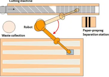
A possible design of a manufacturing cell is shown in Figure 13. The machine that initiates mechanical separation between paper and prepreg should be placed in an area where the robot passes in order to reduce movements. In order to make sure that all backing papers have been removed, the cell could be supervised by an optical system. A simpler way of ensuring that all backing papers have been removed is to weigh the waste in a collection unit.
Figure 13. Suggested outline for an automated manufacturing cell.
FUTURE RESEARCH
Further testing and fine-tuning is necessary in order to prove that the proposed paper removing process is suitable for volume production. A demonstrator cell could give valuable information about how the processes, that have been individually validated, can be integrated into one automation system.
SUMMARY
If an initial separation between the prepreg material and the protective backing paper is made by means of mechanical bending around a support, a standard vacuum gripper can pick up the backing paper. This allows a standard mechanical gripper to access both sides of the backing paper and perform a double-sided mechanical grip that holds the backing paper during the peeling process. The whole process for automatic removal of backing paper can be integrated in an automated production cell for manufacturing of the case product. The sticky problem can be solved!
REFERENCES
1. Åström, B. Tomas. Manufacturing of Polymer Composites. Cheltenham: Nelson Thornes, ISBN 13: 978-0-7487-7076-2, 2002.
2. Buckingham, R.O., and Newell, G.C., “Automating the Manufacture of Composite Broadgoods” Composites Part A: Applied Science and Manufacturing 27, no. 3: 191-200, 1996
3. Putnam, J.W., Seferis, J.C., Pelton, T., and Wilhelm, M., “Perceptions of Prepreg Tack for Manufacturability in Relation to Experimental Measures,” Science and
Engineering of Composite Materials Vol. 4, no. 3: 143-154, 1995.
4. Crossley, R.J., Schubel, P.J., and Warrior, N.A., “The Experimental Determination of Prepreg Tack and Dynamic Stiffness.” Composites Part A: Applied Science and Manufacturing 43: 423-434, 2011.
5. Crossley, R.J., Schubel, P.J., and Warrior, N.A., “Experimental Determination and Control of Prepreg Tack for Automated Manufacture.” Plastics, Rubber and Composites 40, no. 6-7: 363-368, 2011.
6. Newell, G.C., Buckingham, R.O., and Khodabandehloo, K., “The Automated Manufacture of Prepreg Broadgoods Components - A Review of Literature.” Composites Part A: Applied Science and Manufacturing 27, no. 3 PART A: 211-217, 1996.
7. Lukaszewicz, D.H.-J.A., Ward, C., and Potter, K.D., “The Engineering Aspects of Automated Prepreg Layup: History, Present and Future.” Composites Part B: Engineering 43, no. 3: 997-1009, 2012.
8. Lindbäck, J.E., Björnsson, A., and Johansen, K., “New Automated Composite Manufacturing Process: Is it Possible to Find a Cost Effective Manufacturing Method with the use of Robotic Equipment?” presented at SPS 2012, Sweden November 6-8, 2012.
9. Björnsson, A., and Johansen, K., “Composite Manufacturing: How Improvement Work Might Lead to Renewed Product Validation” presented at SPS 2012, Sweden November 6-8, 2012.
10. Umeco, “ARMATURE - Automated high Rate
Manufacture of Automotive composite strucTUREs,” http:// www.advanced-composites.co.uk/
armature_video_download.html, March 2013.
11. Corden, T., Ryder, A., “Automated prepreg processing,” UK Patent Application 2490152, April 20, 2011
12. Lien, T.K., and Davis, P.G.G., “A Novel Gripper for Limp Materials Based on Lateral Coanda Ejectors.” CIRP Annals-Manufacturing Technology 57, no. 1: 33-36, 2008. 13. Angerer, A., Ehinger, C., Hoffmann, A., Reif, W., Reinhart, G., and Strasser, G., “Automated Cutting and Handling of Carbon Fiber Fabrics in Aerospace Industries.” presented at 6th annual IEEE Conference on Automation Science and Enigneering, Canada August 21-24, 2010.
14. Taylor, P.M., “Presentation and Gripping of Flexible Materials.” Assembly Automation 15, no. 3: 33-35, 1995. 15. Stephan, J., and Seliger, G., “Handling with ice-the Cryo-Gripper, a New Approach.” Assembly Automation 19, no. 4: 332-337, 1999.
16. Reinhart, G., and Straßer, G., “Flexible Gripping Technology for the Automated Handling of Limp Technical Textiles in Composites Industry.” Production Engineering 5: 301-306, 2011.
17. Kolluru, R., Valavanis, K.P., Steward, A., and Sonnier, M.J., “A Flat Surface Robotic Gripper for Handling Limp Material.” Robotics & Automation Magazine, IEEE 2, no. 3: 19-26, 1995.
18. Monkman, G.J., Taylor, P.M., and Farnworth, G.J., “Principles of Electroadhesion in Clothing Robotics.” International Journal of Clothing Science and Technology 1, no. 3: 14-20, 1989.
19. Dini, G., Fantoni, G., and Failli, F., “Grasping Leather Plies by Bernoulli Grippers.” CIRP Annals-Manufacturing Technology 58, no. 1: 21-24, 2009.
20. Ozcelik, B., Erzincanli, F., and Findik, F., “Evaluation of Handling Results of various Materials using a Non-Contact End-Effector.” Industrial Robot: An International Journal 30, no. 4: 363-369, 2003.
CONTACT INFORMATION
The corresponding author of this article is Andreas Björnsson
Linköping University andreas.bjornsson@liu.se
ACKNOWLEDGMENTS
The authors wish to thank VINNOVA and SSF for funding the research. Compraser in Linköping and the involved company are equally appreciated for their help and support and their invaluable input in the development of the process.
The Engineering Meetings Board has approved this paper for publication. It has successfully completed SAE's peer review process under the supervision of the session organizer. This process requires a minimum of three (3) reviews by industry experts. All rights reserved. No part of this publication may be reproduced, stored in a retrieval system, or transmitted, in any form or by any means, electronic, mechanical, photocopying, recording, or otherwise, without the prior written permission of SAE. ISSN 0148-7191
Positions and opinions advanced in this paper are those of the author(s) and not necessarily those of SAE. The author is solely responsible for the content of the paper.
SAE Customer Service:
Tel: 877-606-7323 (inside USA and Canada) Tel: 724-776-4970 (outside USA) Fax: 724-776-0790
Email: CustomerService@sae.org
SAE Web Address: http://www.sae.org Printed in USA