BACHELOR THESIS IN
AERONAUTICAL ENGINEERING
15 CREDITS, BASIC LEVEL 300
Project Solaris - Mass and
balance analysis tool for a
ABSTRACT
This thesis work is a part of the Solaris project, a student reasearch project carried out at Mälardalen University. The Solaris Project deals with the development and construction of a SPUAV (Solar Powered Unmanned Aerial Vehicle). The project is divided into four phases; during this first phase a design tools will be is been created for later design and feasibility studies.
This report covers the development of
a computerized
module for this tool. The module allows the user to design the SPUAV and automaticly calculates the mass of the airplane, balance, moment of inertia as well as calculates the loads the aircrafts primary structure is exposed to. It also visualizes the aircraft layout and shape of the aircraft subjected to loads.Date: August 2009
Carried out at: Mälardalen University Advisor at MDH: Gustaf Enebog Examiner: Gustaf Enebog
Sammanfattning
Detta examensarbete är en del av Solaris projektet, ett student projekt som genomförs vid Mälardalens högskola. Solaris projektet behandlar utveckling och konstruktion av en SPUAV (solcellsdrivet obemannad flygplan). Projektet är uppdelat in i fyra faser, under denna första fas ska ett designverktyg skapas och projektets framtidsutsikter undersökas.
Denna rapport beskriver utformningen av en datorbaserad modul till detta designverktyg. Med modulen kan användaren designa flygplanet och låta programmet beräkna flygplanets massa, balans, tröghetsmomentet samt beräkna laster som flygplanets primära struktur utsätts för. Dessutom visualiseras flygplanets layout samt flygplanets deformation under belastning.
Datum: augusti 2009
Utfört vid: Mälardalen Högskola Handledare vid MDH: Gustaf Enebog Examinator: Gustaf Enebog
This thesis work has been performed in Mälardalen University, Västerås in Sweden as a final compulsory work to gain an exam in aeronautical engineering. The work has been carried in the summer of 2009.
I would thank my supervisor and project manager Gustaf Enebog, for all of his work put on this project, I wish the best of luck with the future work on the project.
I would also like to thank the following people:
Jacob Brynolf for his help with physics formulas.
Niklas Bergman for his help with Excel and methods of problem solving. Henrik Johansson for his help with language translations.
Västerås, summer of 2009 Mikko Laukkanen
NOMENCLATURE
α Angular acceleration AR Aspect ratio b Wing span CG Central of Gravity F Force g Gravitation constant 9,82 m/s2Ix, Iy, Iz Moments of inertia X, Y and Z directions
LC Center of Lift
m Mass
M Moment
Ma Aerodynamic moment
MLC Moment doe to LC-GC difference
n Load factor
S Wing area
SPUAV Solar powered Unmanned Aerial Vehicle w Deflection from original postion
CONTENTS
Chapter 1 INTRODUCTION 1 1.1 Background ... 1 1.2 Objective ... 1 1.3 Problem formulation ... 1 1.4 Limitations ... 2Chapter 2 Comparison aircrafts and preliminary design concept 3 2.1 Comparison aircraft... 3 Helios UAV ... 3 Solar Impulse ... 4 QinetiQ Zephyr ... 5 2.2 Design criteria ... 6 Design concept ... 6 Wing panel ... 7 Chapter 3 Method 8 3.1 Program criteria’s ... 8 3.2 Program description ... 8 3.3 Coordinate system ... 9
3.4 Components allocation and layout ...10
Center of gravity ... 10 Moments of inertia ... 11 3.5 Components library ... 13 3.6 Wing panel ... 13 3.7 Force analyses ... 14 Shear force ... 14 Bending moment ... 15 Natural frequency... 15 Deflection ... 16 3.8 Drawings ... 18
3.9 Trial run of program ... 19
Chapter 4 DISCUSSION 20 4.1 Error estimation, limitations and resolution ... 20
4.2 Aeroelasticy ... 20 4.3 User Interface ... 20 4.4 Spar design ... 21 4.5 Wing dihedral ... 21 Chapter 5 CONCLUSIONS 22 5.1 Main insight ... 22
Chapter 7 REFERENCES 24 7.1 References: ... 24
Appendix l 1
Solaris Mass and Balance design tool tutorial ... 1
Appendix ll 15
Chapter 1
INTRODUCTION
1.1 Background
Project Solaris is a student research project at Mälardalen University that aims to develop and build a Solar Powered Unmanned Aerial Vehicle (SPUAV). The project extends over a longer period of time and is divided into four phases, where the first phase makes for the study and conceptual design of the project and initial calculations. A number of optimization and design tools needed for the projects continuity were identified. One important question was the structural integrity of the proposed vehicle. As the aircraft has to be very light due to the meger power availabel, yet strong, it was concluded that a “span-loader” was an interesting candidate to explore. That is, the mass of the aircraft had to be distributed over the span of the aircraft to minimize the wings bending moment. The idea of spanloading aircraft is not new; as early as 1921, the idea of letting the body of the aircraft to contribute to the lift was implemented in the Burnelli RB-1 by Vincent Burnelli. Burnelli also studied the flying wing concept. One of the most extreme spanloading aircrafts was the Helios/patgfinder UAV. For an optimum design, a decision was made to create a mass and balance design tool that would aid in the design of the span-loader aircraft.
1.2 Objective
This project aims to create a development tool for initial estimates of the mass, balance and loads of the Solaris SPUAV. Also the aircraft centre of gravity and moment of inertia is of interest to later work with the control and stability analysis. This mechanical data are to be calculated and presented with good enough reliability for the early evalution of the aircraft. Several other analysis moduls will also be created during this first phase and later to be merged into a complete design tool.
1.3 Problem formulation
One approach to optimize an aircraft design in terms of weight and stiffness is to minimize structural loads and thus reduce the airplane's structural mass; this can be solved by distributing the mass of the airplane on the airplane's lift to cancel the bending moment, i.e. a "span-loader". An airplane consists of numerous parts which make designing and calculation by pen and paper cumbersome; to speed up the design process a computerized design tool is preferred. The tool must be able to let the user add, remove and move components at his or hers desires and present reliable results.
1.4 Limitations
This work deals with the creation of a design modul to make initial calculations of the mechanical properties of a SPUAV and present a primitive sketch of the aircraft. The objective of this thesis work itself is not to design the Solaris SPUAV, i.e. this thesis work will not present the final drawings of the unmanned aircraft. Only some initial examples are worked at to test the program.
Chapter 2
Comparison aircrafts and preliminary design concept
2.1
Comparison aircraft
“Do not re-invent the wheel”. Aircrafts with similar assignments tend to share common design solutions; therefore some comparison aircraft were studied in order to get an estimation about the mass distribution of solar powered aerial vehicles and design of such vehicles.
Helios UAV
Helios is an advanced, experimental aircraft-study carried out by AeroVironment and NASA. Although it is much larger then the proposed Solaris SPUAV, it shares the same basic configurational features with Solaris SPUAV in the way that both are span loaders and powered by the sun, noticeable is that it also has no tail section. In early discussions Helios was the role model for the Solaris project why its structural design has been studied; it had a rather small diameter tubular carbon fiber main spar that has a good torsional stiffness and yet very light (Fig. 2.1). Helios crashed after breaking apart in mid flight due to an exesive pitch oscillation after it encountered some turbulence, an interesting phenomenon that will be discussed in this report.
Solar Impulse
Solar Impulse is a manned solar powered aircraft currently in developement. Solar Impulse carries a human pilot which suggests that design should take safety and reliability into greater consideration than UAV’s. Solar impulse is no true span-loader although some mass distribution over the wing span has been made. Its main spar is made of carbon fiber and has a rectangular cross section. In contrast to Helios, it also takes the full height of the wing airfoil in disposal which indicates that the design is subjected to much higher bending moments. Unlike Helios and QinetiQ Zephyr, Solar Impulse’s mission is to fly a long distance at minimum altitude instead of loitering at a high altitude, which may explain the higher wing load compared to the other two aircrafts.
QinetiQ Zephyr
Zephyr is a project carried out by QinetiQ in the UK. At the time of writing little was known about the structural design for us, but it has a strong resemblance to the Solaris SPUAV in terms of weight, size and mission why the overall design was studied. Its wingtips have a strong dihedral which gives it a very stable flight. As Solar Impulse, it has a conventional tail section.
Summary of data of comparison aircraft:
Aircraft Helios SPUAV Solar Impulse QinetiQ Zephyr
Gross weight 929kg ~2000 kg ~30kg Payload 330 kg (including systems and equipment) One person ~80kg 2kg Wing span 72 m 80 m 18 m Chord 2,4 m 1,7 m 0,6 m Wing loading 5,1 kg/m2 14 kg/m2 3 kg/m2
Tail section None Conventional Conventional
Wing spar design tubular Rectangular unknown
Mission profile Loiter Range Loiter
Operational altitude Design goal up to 100000 feet’s
As low as possibly without
compromising safety
50000-60000 feet’s Fig 2.4 Launch of QinetiQ Zephyr. (QinetiQ)
Fig 2.5 conceptual sketch of Solaris SPUAV (Enebog) 2.2 Design criteria
Design concept
During the first meeting with the Solaris SPUAV workgroup a number of design criteria’s were set, these criteria’s must be taken into account during the work. The initial concept points that were set were:
Span-loading flying wing concept, with or without tail section
High aspect-ratio wings
Rectangular plan form
Modular design with a number of identical wing panels with constand chord and no geometric twist, possibly containing the main bulk of batteries, and covered with solar cells
Avionic and payload pods between wing panels
Propulsion units attached to either wing panels or pods
These will imply, among other things that the main wing spar will be homogenous throughout the wing span, and therefore not an optimum design. However, a conclusion was later made that this imperfection has little impact to the overall performance of the aircraft.
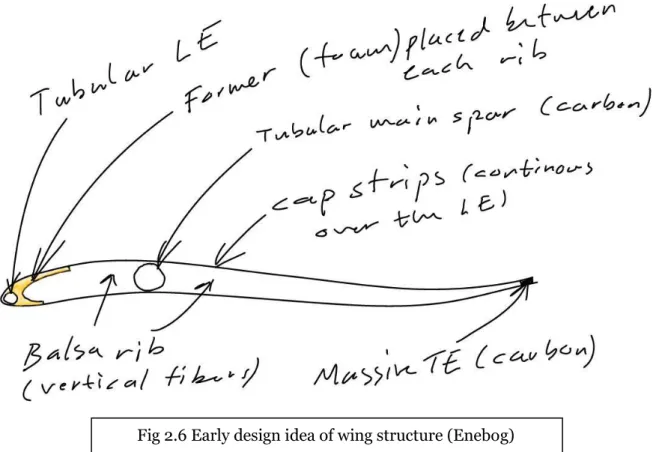
Wing panel
It was decided that the wing panels would be of a conventional design with a wing spar, ribs and skin (Fig 2.6). A number of criteria’s was set to the design:
“Snap on” design with identical panels to easily add or remove panels to change the aircraft span/area
Easy and cheap to manufacture with a assembly line concept
Strong enough for any configuration
The design must meet the structural weight demands on the design
These criteria’s is somewhat
contradictory, and an optimum solution must be
found.
Chapter 3
Method
3.1
Program criteria’s
The work is based on an Excel document that future users will be able to use for developing. At an early stage of the Solaris project there were made a decision that he work will be based on Microsoft Excel, so that all sub-projects will be easily put together into a complete development tool.
3.2 Program description
During the work it was found out that the module will be relatively large and
comprehensive, and in order to create a manageable structure it was decided to categorise the program in to several tabs.
For a transparent structure it was divided into following sub parts:
Component Allocation and layout.
Component library.
Wing Panel.
Force Analysis.
Drawings.
In addition to these tabs, a tab for data collection that is important for the program run but that is of no concern to the user, as long as he or she will not tamper with it.
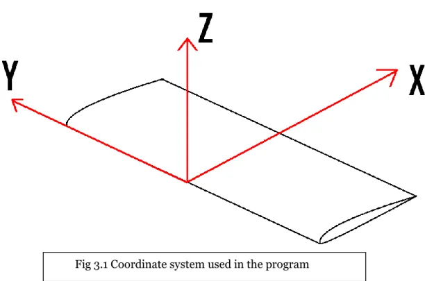
3.3
CoordinatesystemThe design tool uses a coordinate system that is consistent throughout the program. It is a right handed system with X pointing against the direction of flight, Y pointing to the right and Z pointing upwards. The zero reference point is located in the leading edge of the wing.
3.4 Components allocation and layout In this first tab, the
user has the ability to determine the airplane's layout and plan form by determining the number of wing panels (Fig 3.2) and the distance between the wing panels. Also deploy components, by retrieving them from the component library and define their position relative to the airplane's zero reference.
To facilitate programming and to improve ease of use the programme has a limit of seven wing panels, and that all the gaps between the wing panel joints are identical. Not more than 200 components can be inserted in addition to the wing panels. Furthermore, the user can also determine the dimensions of the rudder and aileron and where they are positioned. Rudder and flaps are not included due to the airplane is intended to yaw using differential thrust and the aircraft is believed to not need any flaps. The program continuously calculates the aircraft's total mass m, mass distribution in the different categories and cost by simple addition.
Center of gravity
CG's position relative to zero reference in the respective directions is calculated with the following formula:
(1)
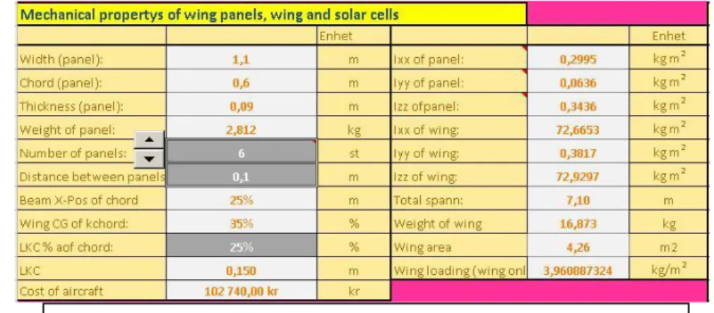
Where d is the distance between the centres of the component to zero reference point and n is the direction of X, Y or Z. The results are presented in the Mass and Balance tab (Fig 3.2).
m
d
m
n nCG
*
Moments of inertia
The moment of inertia of individual components is calculated automatically with the component's weight and dimensions as input. However, moment of inertia is calculated under the premise that the component has a cube format and the mass is homogeneously distributed. This implies that there is a small error in the calculations, but the error is considered to be negligible so that this does not affect the final results significantly. However, the user may manually enter the correct moment of inertia if it is known.
To calculate the moments of inertia of the whole aircraft, the Steiner formula had to be added to component moment of inertia to a common reference point. The reference point is the centre of gravity. Finally the moments of inertia were summed. Steiner formula (formula 2):
(2)
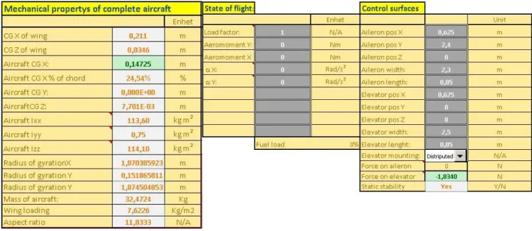
Other data that is calculated is wingspan b, wing area S, aspect ratio AR, and information if the airplane is statically stable or not (Fig 3.3). The later is determined from the relation between the aircraft centre of lift and the airplane's centre of gravity, which is if the centre of lift is located in front of central of gravity, it will be statically stable. In the same tab the user defines the airplanes flight case by inserting the desired role and tip angle acceleration and load factor. This information is later used to determine the deformation and load of the structure. Required force on elevator and aileron to obtain the flight case is calculated and presented when moment of inertia, the desired angle acceleration and position of control surfaces is known. The force on the elevators geometric centre is calculated by following formula:
(3)
Where F is the force on the elevator, α is the desired angular acceleration of the aircraft, IY is the inertial moment in the Y-direction, and dr is the distance between the centre of gravity and the rudder surface centre in the X-direction.
2
* d
m
I
I
CG
o
r LC a yd
M
M
I
F
*
The required force on the ailerons is slightly simpler to calculate, the program presents only the force on the left aileron, the force on the right aileron is equal and opposite to the force on the left side:
(4)
Where F is the force on the centre of the aileron, α is the angular acceleration, Ix is the moment of inertia in x direction and dr is the distance between centre of gravity and centre of rudder. r X
d
I
F
*
Fig 3.3 Final calculations made by the program to the left, state of flight defined by the user in the middle and control surface position also defined by user to the right
3.5 Components library
A separate tab was allocated for the component library where the user defines the various parts name, weight, category, size and cost. The user may also enter comments for each component. The moment of inertia is calculated automatically with the component's weight and dimensions as input. The formula to calculate the moment of inertia that is used is:
(5)
Where Ix is the moment of inertia, m is mass, a and b is the dimension in the z and y-directions.
3.6 Wing panel
Some guidelines for the wing-panel construction were set early in the Solaris project; this has meant that the wing panel can be designed relatively detailed. Design of the wing panel is achieved in a separate tab, which allows the users to define following parameters:
Wing panel width, length and height.
The number of ribs and its dimensions.
If the wing has a leading and / or trailing spar and its position and dimensions.
Wing spar position, profile and dimensions.
What percentage of the wing which is covered with solar cells.
Material data for the entire wing panel components.
The program then calculates the panel components mass, centre of gravity and moment of inertia (formula 5) and then calculates the complete wing panel mass, centre of gravity and moment of inertia using formula 1 and 2. Data for the wing panel are then exported to the Mass and Balance tab for further calculations and analysis. In this tab the user may also specify profile data for visualization of the wing profile in the sketches, profiles has no impact on the program but it aids the user to check if and how the position of the spars fits within the profile perimeters (Fig 3.4).
)
(
*
*
12
1
2 2b
a
m
I
x
3.7 Force analyses
The calculation of the beam loads and deformation proved to be a special challenge due to the fact that the calculations must be made with extensive programming and numerical methods in which one must take into account all the components varying dimensions and position. The solutions was to divide the airplane into 200 sections distributed over the aircraft span and then allow the program to determine how many section that the individual components cut across and distribute component mass at these sections. Next step was to calculate the aerodynamic forces over these points. The lifting force is assumed to be elliptical distributed over the wing and the sum of the lift force is mass times the gravitational constant times the load factor, so the formula for the lifting force of a specific cut will be:
(6)
Where y is the current position of the lifting force along the Y-direction, m is the mass of the aircraft, n is the load factor and g is the gravitational constant. Also, the forces from the control surfaces are distributed.
Shear force
Thereafter, the shear force of the cut is calculated by adding the shear force of the previous cut and current shear force. Iterations formula becomes:
Where SF is the shear force, F is the force in that section and n is the cut station. The shear force is presented by a graph for analysis by the user (Fig 3.5).
78
,
0
*
200
*
*
*
2
1
m
n
g
b
y
L
)
1
(
)
(
)
(
n
F
n
SF
n
SF
Bending moment
Data for shear force is also used for further calculations of the bending moment. The bending moment is calculated by multiplying the shear in the previous subsection with the distance between sections and add the previous moment, the formula becomes:
(7) Where M is the moment, n is the station number, SF is shear and db is the distance between cuts which is the total span of the aircraft divided by the number of stations. Both shear and bending moment is calculated and presented from left to right in the airplane span wise direction i.e. forces which are presented on the right side cut surface at each point (Fig 3.4 previous page).
Natural frequency
In a later stage of the work, while studying the Helios project a major concern was identified, namely issues related to aeroelasticy. To determine the behaviour of the aircraft for example during turbulence a feature to calculate the approximate natural frequency of the wings vertical movment had to be implemented. This value is then used for further calculations, in particular, aeroelasticy in the dynamic case. It proved to be difficult if not impossible to calculate the precise own frequency of the aircraft due to the varying mass distribution; therefore it was decided to use a generic formula:
(8)
Where ω is the angular frequency in radians per seconds, E is elastic modulus, I is the second moment of inertia of the main beam, ѵ is mass per unit length and l is the length of the beam. One must notice that this formula is actually indented to be used for beams with homogenous mass distribution, and therefore not make the presumption that it is an absolute correct value.
db
n
SF
n
M
n
M
(
)
(
1
)
(
1
)
*
4*
*
4
,
22
l
I
E
Fig. 3.6 Theory of the deflection calculations
Deflection
Deflection W (y) - unlike shear force and bending moments – is presented with the centre of aircraft as fixed point. In order to determine wing spar deformation there had to be created special numerical formulas (Fig 3.6) for calculation because the wing is not burdened homogeneous. For each cut there were calculated first the deflection due to moment and force, secondly the direction due to moment and shear force at the cut. Finally the total deflection was calculated by adding deflection due to shear and direction multiplied with the distance between cuts. The formula for deflection becomes:
(9)
Where Wa(n) is the actual deflection from its original position. Wm(n) is the additional deflection due to moment and shear force at that cut and is calculated with the following formula: (10)
)
(
*
)
1
(
'
)
1
(
)
(
n
W
n
W
n
db
W
n
W
a
mI
E
db
n
M
I
E
db
n
F
n
W
m*
*
2
*
)
(
*
*
3
*
)
(
)
(
2 3
I is the second moment of inertia and is defined by the cross section of the main spar. Two cases of cross sections has been implemented in the program which the user may choose from; circular and rectangular. The second moment of inertia of the circular spar is calculated with the following formula:
(12)
Where D is the outer diameter and d is the inner diameter. The second moment of inertia of the rectangular spar is calculated with the following formula:
(13)
Where B is the outer width of the spar, H is the height of the spar, b and h is the outer dimensions subtracted with two times the wall dimensions.
Fig 3.7 Analyses of the forces acting the main spar.
)
(
*
64
4 4d
D
I
12
*
12
*
H
3b
h
3B
I
3.8 Drawings
For a good overview, it has been chosen to present drawings in a separate tab, which incorporated three plan drawings and a three dimensional sketch that the user can rotate with buttons. The sketches are based on the data for the component and wing panel locations. The varying part’s is colour coded to identify the different categories of parts. As seen in the picture below (Fig. 3.8), all components are presented as wireframe boxes. This is an intentional limitation in the program as the goal of this design tool only is to give a rough idea of component location.
3.9 Trial run of program
At the time of completion of the program, there was no proper data to feed into the program, thus estimated values had to be used in the testing of the program. The exmple was designed with a relatively large and slender aircraft with high aspect ratio. The number of wing panels were selected to six and the total wing span 5.3 meters and a chord of 0.4 meters. In order to make room for payload and avionics in the aircraft, it was determined to have a distance of 0.1 meters between the wing panels. This led to the wing panel width of 0.8 m and the aspect ratio of 13.25. As for the visualization of the wing, a wing profile called LA2573A was chosen. The component list tab was fed with data of typical components used in similar aircraft. This included batteries, motors, servos, avionics systems, structural components, load modules and electric current control devices. In the mass and balance tab an avionic pod was placed between the two middle wing panels and payload pods in the other four gaps. In front of each pod, an electric motor, propeller and a speed regulator was added. A total of 10 small batteries were distributed throughout the airplane in a manner hat the aircraft weight distribution was equivalent to lifting distribution and therefore leading to that the various forces acting on the structure would be at a minimum. This was an iterative work where one had to check the force analyses tab for proper load characteristics in both bending and torsion, and then move the batteries accordingly. The total weight was about 6.9 kg, which may be considered normal for an aircraft in this class. At this stage it was discovered that the airplane structure required an extremely feeble wing spar, although the aircraft state of flight was simulated with a high load factor and high role and tip angle accelerations. A very light and yet strong enough structure must be considered to be a positive result. Although one must remember that the aircraft will only handle the specific load in a static flight case.
Chapter 4
DISCUSSION
4.1
Error estimation, limitations and resolution
The software is designed to present an early draft design with limited input data and limited calculation depth. In among other things, the user can only make use of maximum 200 components; minor nuts and bolts must be put together into specific units in the component library which are then used in the “Mass and Balance” tab. in addition, the complete flying wing’s deflection and loads are calculated numerically with only 200 sections which make the resolution of the calculation somewhat limited. There is probably a numerical error in these calculations that has not been estimated at the time of writing this report. Furthermore, the calculations of the deflection, torsion, strength limits and natural frequency is done under the premise that only the main spar acts as the structure, other parts does not contribute to the structural integrity and characteristics.
4.2 Aeroelasticy
At a late stage of the work another concern arose, namely the aeroelasticy impact on the structure, both in static and dynamic case. Aeroelasticy is a cross discipline of both aerodynamics, mechanics and advanced mathematical calculations beyond the level of this thesis work, hence aeroelastic predictions has not been included. However, it has been made some preparations in the design tool for at a later stage implement functions by calculating the structures natural frequency.
4.3 User Interface
Software functionality is driven by the early specifications that were set on the aircraft, resulting in that it is programmed in such a way that it becomes easy for the user to design the aircraft and get fast and easy to read results if the concept is consistent with the initial ideas. However, if the concept is changed in a major way, for example changing the wing plan form from rectangular to tapered, it may require extensive rewriting of the program.
4.4 Spar design
Early in the project's beginning, a number of issues were identified to be addressed, including the main spar bending and torsion. Worries of the beam torsion under load was considered greater than the beam bending why in early discussions it was found that a cylindrical spar would be optimal for the design, because it has the highest resistance to twisting relative to its weight. However, it appears that the bending of the beam, particularly at the turbulent weather when the aircraft may be at risk of being subjected to oscillating bends, should be taken to greater consideration.
The spar have more demands than just withstand the existing loads and have a minimal weight, it must not take too much space in the wing and it should of course also fit within the wing perimeters. Because of reasons mentioned it might be a good consideration to choose a rectangular beam as this design is more volume efficient.
4.5 Wing dihedral
During discussions with the Solaris work group, different wing designs were proposed, of which several had a dihedral wing to improve stability in steady flight. Dihedral wings were not considered when the program were designed and therefore not implemented in the program, although one can come to the conclusion that a mild dihedral angel will probably not affect the overall accuracy of the results.
Chapter 5
CONCLUSIONS
5.1 Main insight
The program has fulfilled all the initial criterias during trial runs and seems to satisfie all the specifications that were set for the program. Though, the program is yet to be used in the Solaris project and has therefore not been fully validated for the intended use. Also, the interaction with the other modules of the design tool has not been tested yet, as during writing this report these has not been fully developed.
Chapter 6
FUTURE WORK
6.1 Compilation of the complete design tool
Preparations have been made as far as possible to put the whole design tool together, but there is no guarantee that it will work smoothly from the outset. It may require some rewriting or write more code in the program in order to use the program fully as intended.
6.2 Future development
Aeroelasticy is a subject which must be evaluated in the future work of the Solaris project. As aeroelasticy has close ties to the mechanical properties calculated by this design tool, it may be a good idea to implement these calculations in the Mass and Balance module.
Chapter 7
REFERENCES
7.1 References:
Teknisk hållfasthetslära - Tore Dahlberg
Engineering mechanics dynamics – fifth edition – J.L Meriam, L.G Kraigh Aerospace Design Engineering Guide -fifth edition.
Project Solaris – phase 1, informal report 1, Vehicle configuration and structure QinetiQ: www.qinetiq.com 2009-08-08 Helios: http://www.nasa.gov/centers/dryden/news/FactSheets/FS-068-DFRC.html 2009-08-08 Solar Impulse: http://www.solarimpulse.com/pdf/challenge/solar_flle_technique_a4_en.pdf 2009-08-08
Appendix l
Solaris Mass and Balance design tool tutorial
Introduction
The Solaris Mass and Balance design tool is created to aid the design and development of a solar powered UAV. The program is based on Microsoft Excel which makes it easy to use and modify if needed. The tool is designed to give fast results; the data can then be exported for further development.
In this tutorial we will see how the design tool is to be used and how to intrepid the results. For this tutorial a UAV with a maximum weight of 7 kg and a span of between 5 and 6 meters will be created.
We will start with the wings and structure of the vehicle. To get a good guestimate of the structural weight, a comparison aircraft is studied. In a presentation of the Solar Impulse aircraft we will find that the approximate weight of the structure of a solar powered aircraft is about 35% of the total weight. With the maximum weight limit of 7 kg this will lead to that the structural weight will be around 2.5 kg
Wing panel
We continue with the wing panels as these are the main bulk of the structural weight. In this case we will be using a total of six wing panels with a distance of 0.1 meters between the wing panels; at an initial state we’ll choose a wing panel width of 0.8 meters, this will give us a total wing span of 5.3 meters. Furthermore we’ll choose a chord of 0.4 meters and a height of 0.06 meters. We insert these values in the “Wing Panel” tab in the program; also we will choose four ribs and two extra spars that will enforce the leading and trailing edge. For now, we also choose a tubular type main spar. The cells were the values is to be inserted is colored grey, these are the only cells where the user may enter data, as tampering other with the other cells may cause the program to stop working properly or all together.
Next, we define the dimesiones, materials and position of the various wing panel components; this is done in the same tab:
As seen in the picture above, we can also choose the materials the components consist of. In this tab we can define how much of the wing panel is covered with solar cells, but for now we leave these empty as solar cells belongs to propulsion and not structure.
Finally the program can present a rough sketch of the wing panel, top view on top and side view below. Ribs in black, leading and trailing edge in yellow, main spar in red:
Component library
Next we need some pods to insert between the wing panels; these are created in the “component library” tab. For each component we define the name, weight, length, width, height and category. We’ll create three types of pods for this aircraft named Avionics pod, Payload pod and Empty pod. Each pod has the height of 0.06 meters, width of 0.1 meters and length of 0.4 meters and define the structural weight of these part to be 0.1 kg. In the scroll down list to the right in the tab we choose the category this part belongs to, the pods is structural, so we choose structures:
At the same time we can define other parts. For this tutorial we search the internet for various parts and find data for motors, batteries, electric load management equipment, servos and avionics, and insert the data in the component library tab:
Mass and balance
Now we move to the “Mass and Balance” tab to create the complete wing assembly. Under the “Mechanical properties of wing panels, wing and solar cells” section we choose the number of panels the wing consist of and the distance between the wing panels, we also have another cell marked grey that should be filled in; this is the aero dynamical center of lift described as per cent of chord. This value is used in calculating the stability of the aircraft. As most wings have its aero dynamical center of lift about the one quarter mark of the wing, so we put 25% in this cell.
Now we can have a peek at the aircraft we got so far:
We can see six rectangular blocks that represents the wing panels with gaps between them; we can also see the ailerons and elevator attached to the wing. The rudder position and dimensions are defined in the current tab under the title “Control surfaces”, for this aircraft we let the whole trailing edge consist of rudders as seen above. We can also see in the “Control surfaces” section how the control surfaces have to be loaded to keep the current state of flight. The program also tells us if the aircraft is statically stable or not. At the current state of creating, the aircraft is staticly unstable due do the fact that the center of gravity is behind the aero dynamical center of lift. For this particular aircraft we wish a stable vehicle so we must place more weight at the front. We cannot move any parts we have for now, so we have to use other equipment to stabilize the aircraft.
To finalize the structure, we fit the pods between the wing panels; this is done under the “List of components” section. We choose the component from the scroll down list and define its position:
As you may notice, the component properties is automatically imported from the “Component Library” tab, all we have to do is to define the position of the components. In a similar fashion, we place the motors and propellers. For this aircraft, I have chosen to have one engine in front of each pod; also we finalize the wing panels by covering the upper surface of the wing with solar cells (“Wing Panel” tab). Now we have something that resembles a flying wing:
Before we move on, we have to make sure that input values for the force analyses simulation is correct, this is done under the “State of flight” section, for now we’ll simulate a steady flight:
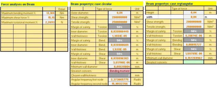
Force analyses
At this state we move to the “force analyses” tab to check how the aircraft behaves in flight:
As seen in this graph, the wing tips slopes down about six centimeters, this indicates that the mass distribution is not optimal. To cure this issue, more weight should be placed in the middle of the aircraft, so we move back to the “Mass and Balance” tab and place some additional equipment needed for the finalized aircraft.
After that I have added the flight control unit, wire loom and servos the total weight is about 4.6 kg, this lefts us with 2.4 kg to distribute to the batteries. For the batteries I have chosen a Li-Po battery type weighting in at 0.166 kg, this gives us 14 batteries to distribute throughout the wing. In this final work we must make sure that the mass distribution and the center of gravity is correct, this can be an iterative work where one must check the “force analyses” tab and move the batteries accordingly.
After some tinkering, the deflection of the wing in steady flight is only three millimeters and the center of gravity is precisely in front of the aero dynamic center of lift. Also the weight ended on 6.992 kg. Notice that the graph is somewhat odd, this due to the scale effect of the axis.
To test the structure, we change the state of flight to have a high angular roll acceleration and high load factor in the “mass and Balance” tab:
As one can see from the above picture, the forces acting on the structure is excessive, and the structure i.e. the main spar has to be strengthened. To do so I chose to change the spar to a rectangular type and set the height of the spar to 0.05 and the width to 0.02 meters and increase the wall thickness from 1 to 1,7 millimeters (“Wing Panel” tab). But by doing so, the weight increased to 7.5 kg. This is unacceptable as the weight limit is 7 kg, so to solve the weight problem; I removed four batteries and moved the other batteries to spread the weight more evenly (“Mass and Balance” tab). Finally the aircraft is finished and we can take a look at the final product.
Final results
As seen from the above tables, we can see that the aircraft fulfills the initial design criteria’s. The wing loading, 3.2514 kg/m2, correspond to other similar aircraft of its type which suggest that the aircraft has good loitering capacities.
Drawings of the finalized aircraft
All of the above pictures can be seen in the “Drawings” tab.
In the picture bellow, the basic wing structure can be seen, with the main spar in red and leading and trailing edge in yellow (“Wing Panel” tab).
Appendix ll
Other aircrafts designed with the design tool
Same aircraft as in appendix ll but with tail section, motors moved forwards to compensate the weight shift due to the added weight of the tail section.
Known bug in the design tool
The force analyses calculation may fail to function if any component does not span a calculation station; this problem is easily identified and fixed:
To indentify the problem, check the “Mass and Balance” tab ” control surfaces” section “Force on elevator” cell. If this cell says #####, this particular problem has occurred. To solve the issue, you may widen a component that is to narrow in the “Component Library” tab or move the part so that it spans over a calculation station. The problem may also occur when a component is removed; this is solved by mowing the “empty component” to the center of the aircraft in the Y direction.