S T A T E N S V Ä G I N S T I T U T
S T O C K H O L M
M E D D E L A N D E 76DISTILLATION ANALYSIS
OF ROAD TARS
Metoder fö r destillationsanalys
a v vägtjäror
BY S T E N H A L L B E R G and H A R R Y A R N F E L T1 9 4 9
S T A T E N S V Ä G I N S T I T U T
S T O C K H O L M
M E D D E L A N D E j 6DISTILLATION ANALYSIS
OF ROAD TARS
Metoder fö r destillationsanalys
a v vägtjäror
B Y S T E N H A L L B E R G and H A R R Y A R N F E L Ti 9 4 9
S T O C K H O L M I 9 5 O
I V A R H £ G G S T R Ö M S B O K T R Y C K E R I A . B.
T A B L E OF C O N T E N T S
Page
F ö re ta l... 4
Introduction ... 5
Brief Description of the German, British and American Standard Methods 6 The German Standard M e th o d ... 6
The British Standard M e th o d ... 7
The American Standard M eth o d ... 8
Comments on the three Standard M ethods... 10
General remarks ... 10
Comparison of the M eth o ds... 1 1 Development of the Modified M e th o d ... 12
Tests made by some of the Swedish Gas Works and the G O K E F ... 1 7 Concluding R e m a rk s... 19
FÖRETAL
I
S Y F T E A T T K L A R L Ä G G A sammansättningen av en vägtjära brukar man utföra en fraktionerad destillation av tjäran. Vid denna destillation har man i Sverige tidigare använt en tysk standardmetod, beskriven i de tyska normerna D IN 1995, U 16. Metoden var dock i några avseenden icke fullt tillfredsstäl lande, varför väginstitutet beslöt att pröva de metoder, som voro standardiserade i U SA och Storbritannien. Dessa metoder visade sig i vissa avseenden vara bättre än den tyska, men i andra avseenden sämre. Följden blev att en modifierad metod utarbetades, vilken i sig förenade de olika metodernas fördelar men und vek deras nackdelar.Denna modifierade metod har prövats under ett par års tid, dels av väginsti tutet och dels av Gokef och därvid visat sig vara tillfredsställande. Den användes nu som svensk standardmetod för destillationsanalys av vägtjäror.
Metoden ger praktiskt taget samma resultat som de tyska, engelska och ameri kanska metoderna, varför de i normalbestämmelserna för de olika tjärfraktio- nerna angivna procenttalen icke behövde ändras vid övergången till den nya metoden. Fördelarna med denna äro i första hand provningstekniska. Den är lättare att arbeta med än de tyska och engelska metoderna och har framför den amerikanska den fördelen, att de utvunna destillatmängderna äro så stora, att fenol och naftalinhalterna kunna bestämmas.
Enär meddelandet huvudsakligen behandlar analysmetodik och därför i första hand är av intresse för laboratorietekniker har det i sin helhet avfattats på engelska.
IN TRO D U CTIO N
I N S W E D E N D I S T I L L A T I O N A N A L Y S E S of road tars were performed until
recently according to the German standard method D IN 1995 U 16. This method proved, however, not to be entirely satisfactory and the question of its replace ment by a more suitable method was raised. In the course of a search for a better method, the standard methods of the United Kingdom and the U. S. A. were studied. A consequence of this study was the development of a modified distilla tion method giving satisfactory results and being free of some inconveniences pertaining to the other methods.
The modified method was tested in routine work in the Association for the By-products from the Swedish Gas and Coke Industries, the Gas- och Koksver-
kens Ekonomiska Förening (G O K EF), and in the laboratories of the Swedish Gas
Works. In 1947 the modified method and the German standard method were both applied on the same samples. In 1948 the modified method alone was used in routine work in Sweden. After two years’ favourable experience of the modified method, it was adopted as the Swedish standard method for the distilla tion analyses of road tars.
In the following pages a brief survey is given of the German, British and American standard methods. The experiences gathered in the course of some tests made by the Road Institute are also reported. In addition, modifications of the distillation methods are discussed and, finally, a description is given of the method which was arrived at.
BRIEF DESCRIPTION OF
THE GERMAN, BRITISH AND AMERICAN
STANDARD METHODS
The German Standard Method
D e u t s c h e N O R M E N A U S S C H U S S: D IN 1995 U 1 6 . Siedeanalyse von Stras- senteer und Kaltteer. Bituminöse Bindemittel fiir den Strassenbau, published by Beuth-Vertrieb, Berlin, 19 41.
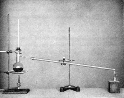
The distillation apparatus (Fig. 1) consists of a 500 ml distillation flask con nected to a glass tube, 800 mm in length and 20 mm in external diameter, serving as an air-cooled condenser. (For tars of low viscosity a water-cooled condenser is used for the distillate obtained under 17 0 ° C). The angle between the con denser tube and the neck of the distillation flask is 85°.
A total immersion thermometer is fitted in the flask so that the top of the bulb is level with the lower edge of the side tube joint. The flask is placed upon an asbestos-lined iron gauze and is heated with a gas burner. No draught shield is used.
The quantity of sample taken for one distillation analysis is 250— 300 grams. The distillation rate is 2 drops per second. The fractions are collected separately in conical flasks at specified thermometer readings. The distillation is ended when the thermometer reading is 350° C. Water is collected separately. The quantity of the final distillate (300— 350° C) and of the residual pitch are corrected by means of a correction formula to a standard grade of the pitch, which has a softening point of 6y° C according to the Krämer-Sarnow test. The specifications do not mention how to deal with solid substances, which might form in the condenser.
The results are reported in percentages by weight of the sample.
The British Standard Method
S t a n d a r d i z a t i o n o f t a r p r o d u c t s t e s t s c o m m i t t e e Serial R. T. No. 5— 38. Distillation, Standard methods for testing tar and its products, Lon don, 1938.
The distillation apparatus (Fig. 2) consists of a distillation flask with a volume of approximately 1 000 ml equipped with an air condenser of glass with an overall length of 600 mm and an internal diameter of 20 mm. The length of the side tube between the wall of the draught screen, described below, and the con denser is approximately 10 mm. The side tube of the distillation flask and the condenser slope downwards, forming an angle of 7 5 0 with the neck. A partial immersion thermometer is fitted into the flask in such a w ay that the bottom of the capillary is level with the lower edge of the side tube joint.
The flask is placed in a draught screen divided into two compartments by a horizontal hard asbestos board that has a central circular hole, which is closed by the bottom of the flask. The flask is heated by a large size gas burner. The upper part of the flask is completely shielded from the hot gases from the gas burner and is protected from draught by the sides of the draught screen, but is not protected against heat losses by any cover on top of the screen.
The quantity of sample is 750 g. If the sample contains water exceeding 0.5 per cent, the water is removed by a distillation prior to the distillation analysis.
The distillation rate is 5 ml per minute or about 1 V2 drops per second. The thermometer shall indicate 2000 C within 35 minutes from the start. I f solids tend to deposit during the distillation, the condenser is warmed so that such solids are collected in the fraction to which they belong. When the thermometer indicates 300° C the gas burner is extinguished and the oil remaining in the condenser is allowed to drain from the condenser for five minutes after the flame has been extinguished.
The fractions are collected separately at specified temperatures in Crow receivers, i. e., graduated glass cylinders that are conical at the bottom. The softening point of the residue is determined by the Ring and .Ball or by the Krämer-Sarnow tests.
The results are reported in percentage by weight of the sample.
The American Standard Method
A m e r i c a n s o c i e t y f o r t e s t i n g m a t e r i a l s. Designation: D 20— 30: A. S. T. M. Standards, Part II, Non-metallic materials, Philadelphia, 1930.
The American Association of State Highway Officials. Designation: T 52— 42. Standard specification for highway materials and methods of sampling and testing, Part II, Methods of sampling and testing, Washington, 1942.
The distillation apparatus (Fig. 3) consists of a distillation flask with a volume of approximately 300 ml equipped with an air-cooled tapered glass condenser tube of an overall length of 360 mm and an outside diameter at the small end of 12.5 mm. The length of the tapered part is 100 mm and the outside diameter of the large end is 28.5 mm. The length of the side tube between the wall of the draught screen and the condenser is not less than about 90 mm. The downward slope of the side tube and condenser tube is such that the angle between the axes of the tubes and the neck is 7 5 °.
Fig. 3. T h e A . S. T . M. distillation apparatus
A total immersion thermometer is inserted in the flask with the top of the bulb level with the lowest point of juncture of the side tube and the neck of the flask.
The flask is shielded from draughts by a cylindrical iron screen lined with asbestos and provided with a top cover. The neck of the flask emerges about 20 mm through a hole in the cover. The flask is supported by two sheets of iron wire gauze with 8 wires per cm, and is heated with a gas burner protected from draughts by a chimney.
The quantity of sample is 100 g. I f the percentage of water exceeds 3 per cent the water is removed by a special distillation before the distillation analysis.
The distillation rate is about 1 drop per second. The first drop shall appear 5— 15 minutes after the heat has been applied. Fractions are taken when the thermometer indicates specified temperatures. The condenser is warmed when necessary to prevent accumulation of solid distillates. When the thermometer indicates 300° C (or 350° C for low viscosity tars) the flame is removed, and the oil in the condenser is allowed to drain into the last fraction. The softening point of the residual pitch is determined by means of the Ring and Ball test. The results of the distillation are reported in percentages by weight of the water-free material.
COMMENTS ON THE TH REE
STANDARD METHODS
General remarks
The German Standard MethodTh e S T A T E R O A D I N S T I T U T E gathered a great deal of experience in this method during several years.
In the cases when the tars contained even small amounts of water, a condensa tion of the water occurred in the upper parts of the bulb and the neck of the distillation flask. Drops of condensed water ran down into the hot tar causing it to froth and sputter. In some samples an excessive frothing took place. In order to avoid these difficulties it was found necessary to use rather a low distillation rate or to heat the neck of the flask with a small flame. Many operators using the German standard method seem to heat the neck, although this procedure is not mentioned in the German specifications. When the tar was liable to excessive frothing and sputtering in spite of the extra heating of the neck, it sometimes occurred that the distillation rate had to be held so low that a single distillation required several hours.
According to the specifications, the distillation flask should be supported by an asbestos-lined wire gauze. A bare wire gauze was substituted for this gauze, as it proved difficult to keep the specified distillation rate and to raise the temperature above 300° C, even when three burners were used for heating. In spite of this, it was still difficult to reach the specified final temperature of 350° C. The excessive heating often effected carbonization of the tar at the bottom of the flask, which for this reason became over-heated and attained such a high temperature that it softened and was deformed.
Owing to the comparatively slight slope and the length of the condenser tube, the drainage of the water was rather slow, with ensuing difficulties in the deter mination of the water. Stagnant drops of water were removed by the tar oils and came into both the first and the second fractions, instead of being collected quantitatively in the first fraction.
For the same reasons a large part of the naphthalene and the anthracene very often solidified in the condenser tube. In order to avoid this trouble it was nearly always necessary to heat the condenser tube. This was done with a small flame. Heating the condenser, however, incurred the risk of a loss of some of
the distillate. Moreover, it was difficult to control the proper distillation rate, owing to unavoidable fluctuations in the drainage from the condenser of the molten substance.
The British Standard Method
When the British standard method was studied, it was found that the heating of the distillation flask met with some difficulties. The burner house of the draught screen attained an inconveniently high temperature. The condensation of water in the neck was nearly as troublesome as in the case of the German standard apparatus. It was also difficult in some instances to obtain a sufficiently high distillation rate at high temperatures.
Compared with the German standard apparatus the British one has the advan tage of having a condenser tube which is shorter and slopes more steeply down wards. This highly diminishes the risk of solidification of naphthalene and anthracene and facilitates the draining of the water into the receiver.
The American Standard Method
With this apparatus only a few distillations were made. No difficulties were encountered. No condensation of water occurred in the neck of the flask, presum ably owing to the flask being enclosed in the draught screen except for its upper most part.
The quantity of the sample, 100 g, is rather small. The fractions are corre spondingly small, which makes it difficult to obtain the desired accuracy. I f the phenol and the naphthalene contents are to be determined, the method is not suitable because of the smallness of the fraction taken for these determinations.
Comparison of the Methods
In order to get an idea of the relative results given by the three standard methods, specimens from some tars were distilled according to all the three methods. The specifications were followed as closely as possible, but some devia tions had to be made. Especially when distilling according to the German speci fications, it was necessary to substitute the asbestos-lined iron gauze for an ordi nary gauze and heat the neck of the distillation flask. When working according to the British specifications the collection of the fractions up to 200° C always required a longer period than that specified.
The road tar specifications of the different countries have, however, different temperature ranges for the fractions. For that reason the comparison had to be confined to the two fractions that are common to all the three specifications, viz., up to 270° C and 270— 300° C.
Water could be collected only with the German and the British standard appa ratuses. The latter apparatus gave somewhat higher values of the water content,
which is not astonishing in view of what has been said of the drainage of the water. Presumably the differences might be due also to the different ways of collecting the water. The German standards specify that the water should be collected in a separate flask, while the British standards specify that the water should be collected in a graduated cylinder together with the oil fraction up to 200° C. The latter procedure allows the water to be quantitatively carried down with the oil in the comparatively steeply sloping condenser.
For the fraction up to 2 jo ° C the American and the German apparatuses
yielded slightly lower percentages than the British one. The percentages for the
fraction 270—jo o ° C yielded by the German apparatus were somewhat lower
than those yielded by the American and the British ones.
The experimental results are too few to allow any far-reaching conclusions as to the experimental errors and the degree of agreement between the different methods, but on the whole the three methods appear to give practically the same results.
Development of the Modified Method
During the study of the standard methods it was found that the least difficul ties were met with when the American standard method was used. This fact was ascribed to the construction of the draught screen. It was thought that the per formance of the other standard apparatuses could be improved, if draught screens of the American type were used.
Draught screens were designed with the American screen as a model, but made to fit the distillation flasks specified by the British and German standards. Such a screen consisted of an asbestos-lined sheet iron cylinder having a slot at the upper edge for the side tube of the flask and provided with a top cover and two mica-covered observation windows. The cover was made of a circular asbestos- lined sheet iron divided into two halves. In the center of the cover was a hole through which the uppermost part of the neck emerged. The diameter of the cylinder was 20— 30 mm larger than that of the distillation flask, and its height was such that the top of the neck reached 20 mm above the cover.
As a support for the draught screen and the flask a tripod covered with two sheets of iron gauze was used. As regards the other details of the distillation apparatus the specifications of the corresponding standard method were followed.
With the above type of draught screen the distillation of the water present in the tar was rapid. It was also easy to maintain the specified distillation rate with a comparatively small heat supply. The results of the distillation analyses per formed according to the German specifications are given in Table 1, and those according to the British specifications in Table 2. The columns A comprise results obtained with the standard methods proper and columns B results obtained when the distillation flasks were provided with the new draught screens. (For columns C, see below).
Table i. Distillation analyses with different apparatuses, performed according to the German specifications as to the method of distillation.
The German specifications were followed with regard to temperature ranges of the fractions, distillation rate and correction of the softening point of the residual pitch.
The apparatuses used were: Columns A . German standard apparatus. Quantity of the sample 2 50 — 300 g.
Columns B. German standard apparatus with the draught screen shown in Fig. 4. Quantity of the sample 250— 300 g.
Columns C. British apparatus with the draught screen shown in Fig. 5. Quantity of the sample 350 g.
Registration number Grade1 Water Per cent by weight Fraction Up to 17 0 ° C Per cent by weight Fraction 17 0 0— 2 7 0 ° C Per cent by weight Fraction 2 70 0— 30 0 ° C Per cent by weight Fraction 3 0 0 °— 3 5 0 ° C Per cent by weight (Corrected) Residue (Corrected) Per cent by weight Distillation losses Per cent by weight A B C A B C A B c A B c A B c A B c A B c S.V. 202 . . T 1 5 1.0 1 .1 1 .0 0.6 0.7 1.5 21.5 20.5 21.0 4.6 4.6 19.7 17.5 19.2 52.0 51-9 51-4 0.6 0.7 0.8 S.V. 192 . . T 55 0 O O 0 O O 8.4 6.0 8.0 4.8 7-i 6.3 26.4 28.4 23-3 59-9 58.2 62.5 0.5 0.3 O S.V. 2502 . . T 6 0 I 0 0.2 — 0 O — 9.0 4-5 — 3-7 6.0 — 1 5 . i 20.3 — 70.9 68.2 — 1.3 0.8 — II 0 — — 0 — — 6 .9 — — 5.8 — — 17.0 — — 69.0 — — 1.3 — — S.V . 2669 . . T 6 0 I 0.2 0.2 — 0 O — 9.8 6.5 — 5-1 5.2 — i3-i 16.2 — 70.4 7 '.5 — 1-4 O.4 — II 0.3 — — — - — 10.2 — — 2.8 — — 15.6 - — 70.4 — — O.7 — — S.V . 2 6 7 0 . . T 6 0 I 0 O — 0 O — i 0.9 7.6 — I O.o 7-9 — 14.8 21.4 — 64.3 62.7 — O 0 .4 — II 0 — — 0 — — 9-3 — — 7.8 — — 18.8 — — 63.6 — — 0.5 — — S.V . 26 71 . . T 6 0 I 0.4 0 .2 0 .2 0 O.I O.I 7.8 4.2 6.2 7.6 6.9 6.7 21.6 23.8 22.6 6 1.6 64*3 62.9 r .0 0-5 1.4 II 0.2 — — 0 — — 5.2 — — 6.1 — — 23.7 — — 63-7 — — 1 . 1 — —
Table 2. Distillation analyses with different apparatuses performed according to the British specifications as to the method of distillation.
The British specifications were followed with regard to temperature ranges of the fractions and distillation rate. The apparatuses used were: Columns A. British standard apparatus. Quantity of the sample 750 g.
Columns B. British standard apparatus with the draught screen shown in Fig. 5. Quantity of the sample 750 g.
Columns C. » » >> » » » » f- » » 350 g. Registra tion number Grade1 Water Per cent by weight Fraction Up tO 200° C Per cent by weight Fraction 2 0 0 °— 2 7 0 ° C Per cent by weight Fraction 2 7 0 °— 30 0 ° C Per cent by weight Residue Per cent by weight Softening point of the residue. Ring and Ball. 0 C Distillation losses Per cent by weight Tim e3 to 200° C Minutes A B c A B c A B c A B c A B c A B c A B c A B c S.V. 202 T 1 5 0.9 0.8 I . 0 3-5 3-o 4.0 20.3 I9.6 19.0 5-9 6.5 6.2 68.8 69-5 69. 2 40 39 38 0.6 0.6 0 70 40 25 S.V. 192 T 55 0 O 0 0 0 0.2 10.4 9-1 9.0 7.0 7.6 7.8 82.3 8 3 - 82.7 36 38 38 0.3 0.2 0.3 45 25 18 S.V . 2502 T 6 0 2 — 0.5 — — 0.1 — — 6.8 — — 6.4 - — 86.3 — — 40 — — O — — 45 — S.V. 2669 T 6 0 0 . 6 0.5 — 0 . 4 0.3 — 9.0 9.1 — 6.4 5-° — 83.4 84.9 — 47 47 — 0 .2 0 .2 — 50 45 — S.V. 2670 T 6 0 I 0 . 2 O.i — 0 . 2 0 . 2 — •3-5 12.3 — 9-3 8.0 — 76.5 79.2 ~ 56 52 — 0.3 0 . 2 — 45 38 — II O.T — — 0 . 2 — — 1 2 . 4 — — 1 2 . 3 — — 74-7 — — 58 - — 0 . 3 — — 45 — — S.V . 2 6 71 T 6 0 0-5 0.5 0 . 3 0.2 0.2 0.4 7 . * 6.9 6 . 3 7.8 7-4 8.8 84*2 00 VO 84.I 4 3 43 44 0.2 O. T 0.1 49 40 20
1 See foot-note on page 15.
2 It was not possible to obtain the specified distillation rate, when distilling according to the British specifications. 3 Period of time for bringing the temperature up to 200° C.
One objection to the German standard method was, as has been mentioned, that the draining of the water from the condenser was unsatisfactory. From the shorter and more sloping British condenser tube, on the other hand, the water was drained satisfactorily.
The sample taken for the British distillation analysis seems to be inconvenient ly large, 750 g; at least when distilling such tars which comply with the Swedish specifications for road tars. About half this quantity would generally suffice for these tars. The use of a smaller sample would shorten the distillation time. (Table 2, last column.)
Having these observations in mind, it can be stated that for the sake of easy operation the distillation apparatus should be equipped with a draught screen of the American type and a condenser of the British type. The sample taken for analysis should be about 350 g, a little more than that stated in the German specifications. Moreover, the volume of the flask should be comparatively large to lessen the trouble of frothing and sputtering.
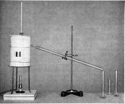
Figs. 4 and 5 show the apparatus proposed by the Road Institute. The volume of the distillation flask in this apparatus is 1 000 ml and may seem to be rather large for a sample of only 350 g. However, with this big flask the distillations run more smoothly and another advantage is that a British standard apparatus can be used, with the exception of the draught screen.
The distillation tests with this apparatus have been easy to perform in all respects. Naturally, the tests might be performed with respect to distillation rate, etc., according to any specifications. The results obtained, when following the German specifications, are given in Table 1, columns C, and those obtained when following the British specifications are given in Table 2, columns C.
N ote concerning the tables on pages 13 , 14 and 18
According to tentative Swedish Standard Specifications, the bituminous binders (asphalt bitumens, tars and cut-backs) are denominated by a letter indicating the type of binder (A for asphalts, T for tars, R A for rapid curing, M A for medium curing and S A for slow curing cut backs) and a figure giving the temperature at which the binder has a viscosity of 5 Stokes, i. e., the highest average viscosity which still gives a homogeneous mix with a rather fine-grained aggregate when the binder is mixed with the aggregate in a good mixer. Thus the tars T 15 , T 55, the cut-back M A 90 and the asphaltic bitumen A 140 attain, when heated to 1 5 0, 5 5 0, 9 0 ° and 140 0 respectively, the same viscosity, viz., 5 stokes, which also can be considered as the maximal binder viscosity for a satisfactory mixing with aggregates.
The standardized Swedish road tars have approxim ately the follow ing viscosities:
Grade V i s c <3 s i t y Approximate E. V . T . (British Method) Standard Tar 4 mm cup 20° C Seconds • Viscometer 10 mm cup 3 0 °C Seconds T 15 * 25 (appr.) (—6°C ) T 55 35 (appr.) 28°C T 60 80 > 33° C T 65 I 70 » 37° C
* T 15 is a priming tar for gravel roads similar to the American priming tars. It is so fluid that its E. V . T . is below zero. A t that temperature, however, the tar often has ceased to flow owing to crystallization and similar phenomena.
Fig. 4. T he proposed distillation apparatus
T E S T S M A D E B Y S O M E O F T H E S W E D I S H
G A S W O R K S A N D T H E G O K E F
In 1947 a number of distillation analyses were made by the Government
Institute for Testing Materials at the request of the G O K EF, and by the Gas Works in Stockholm and Göteborg which all used the German specifications. The
distillation, however, was ended at 300° C. The distillation analyses were dupli cated by the G O K EF using the proposed method. Mr. Rosengren, Chief Chemist of the G O K EF, states that “ the method proposed by the State Road Institute is more suitable for routine work than the German standard method of which the G O K EF previously had a great deal of experience. Thus, when distilling accord ing to the proposed method, no condensation of water occurs in the neck of the distillation flask. The deposition of solids in the condenser tube is comparatively small.”
Table 3 presents the results of these tests. The headings of the three last columns are defined as follows:
Average value =
2
’ (a + b) / m ; Mean d iffe re n c e s ^ (a—b) /n;Standard deviation (of a single difference from the mean difference) _j_ / [(a—b) — mean difference]2?
V
n — 1where “ a” means the percentage obtained from a single distillation in the German apparatus, “ b” the percentage obtained from a distillation of the same sample in the modified apparatus and “ n” the number of tests. The same definitions also apply to the softening point, with temperature substituted for percentage.
A study of the table shows that when the German apparatus is used, the per centages of the oil fractions are somewhat higher. This is especially the case for the fraction 17 0 °— 270°. Moreover, the standard deviation in this case shows that the difference is significant.
The percentage of the pitch residue in the German apparatus is significantly lower. The softening point of the pitch is correspondingly higher.
A study was also made of the influence of the size of the sample and the size
of the flask upon the percentages of the fractions.
Three tars of different grades: T 15, T 55 and T 60 were distilled in a 500 ml flask as well as in a 1 000 ml flask. The quantity of the sample was 350 g. Furthermore different quantities of the tars were distilled in the 1 000 ml flask, viz., 300, 350 and 400 g.
Table j . Results o f tests made by the GO K E F and the Gas Works. Grade of tar1 Number of distillation tests Average value Mean difference Standard deviation
W ater Per cent by weight 1 + 0.2 + 0.2
Fraction up to 17 0 ° C » » » » 2 • f 0.3 +_ 0.2
T 15 35 VI 0 0 1 K» V| O O O V 2 3 + 1.0 +. 0.3
K) V| O 0 1 KjJ O O O O 6 + 0 .1 + 0.4
Pitch residue » » » » 68 — 1.5 + 0.4
Softening point of pitch residue (R .& B .)°C 46 + 2 ± 1
W ater Per cent by weight 0 _ _
Fraction up to 1 7 0 ° C » » » » 0. i — —
T 60 18 » 1 7 0 ° — 2 7 0 ° C » » » » 9 + 1 . 1 +. 0.4
» 270 0— 300° C » » » » 6 -f- 0 .2 + 0.2
Pitch residue » » » » 85 — I . 4 ± 0 . S
Softening point of pitch residue (R .& B .)°C 43 + I ± I
W ater Per cent by weight 0 _ _
Fraction up to 1 7 0 ° C » » » » 0 — —
A T 6 0 2 27 » 17 0 0— 2 7 0 ° C » » » » 10 + O.3 +. 1.3
» 2 7 0 °— 3 oo° C » » » » 6 -f- 0 . 2 ± 0 . 5
Pitch residue » » » » 84 ---- 1 . 2 + 0 . 6
Softening point of pitch residue (R .& B .)°C 43 + I ± I
1 See note on page 15.
2 T a r containing about 15 per cent of asphaltic bitumen.
Neither the size of the flask nor the size of the sample had any appreciable influence on the percentages of the different fractions. The mean value of a per centage of a fraction obtained with the 500 ml flask coincided often with that obtained with the 1 000 ml flask. When a deviation occurred it was within the limits of the expected experimental errors. The standard deviation of a single determination was, however, considerably lower when using the 1 000 ml flask than in the case of the 500 ml flask.
CO N CLU D IN G REMARKS
1H E E X P E R I M E N T S P E R F O R M E D for the comparison of the different methods are not numerous. It is, however, of no great importance to know e x a c t l y how much the results given by the various methods differ from each other, considering the wide ranges of the percentages of the different fractions specified for road tars. No attempt was therefore made to obtain more precise information through an extended series of tests.
As far as can be judged from the experimental material, all the distillation methods were found to yield the same results within the limit of the experimental errors. This, however, implies that the relative quantity of the different frac tions was chiefly a function of the composition of the tar and that the con struction of the distillation apparatuses had but a secondary influence.
These results are to be expected from a consideration of the character of distillation in such a simple apparatus as a flask provided with a condenser. The composition and the relative quantities of the fractions obtained from a distilla tion apparatus are dependent on the composition of the vapour phase in the vicinity of the liquid surface and the degree of fractionation occurring when the vapour passes on its w ay to the condenser. I f the reflux ratio (i. e., the ratio between the quantity of reflux to the quantity of condensate) is small or prac tically nil, as in a simple open distillation, the fractionation is insignificant and the vapour entering the condenser therefore has nearly the same composition as the vapour above the surface of the liquid. In this case the distillation is virtually a transport of vapour from the surface of the liquid to the condenser without any appreciable change in its composition. The reflux ratio is determined by the construction of the apparatus and the distillation rate. In the standard apparatuses the reflux ratio is low and the fractionation is consequently small.
From the point of view of the road maker, who is interested in knowing some thing about the evaporation of the components of his tars in the open air, a distillation analysis with as small a reflux ratio as possible, approaching that of a simple open distillation, seems to be the soundest one. The modified method and the American standard method seem most suited to the needs of the road maker in this respect. An advantage of the modified apparatus is the absence of sput tering caused by w^ater which is obviously due to the smaller reflux ratio. The operator has little trouble in performing the distillations with the specified distillation rate, which means it is more practical for laboratory routine work.
On the next page the principal data of the modified method, now adopted as Swedish Standard, will be given.
DATA OF THE MODIFIED METHOD
1H E D I S T I L L A T I O N A P P A R A T U S is identical with that specified by the British
Standardization of T ar Products Test Committe described in Standard Methods for Testing Tar and its Products and designated by R T j —38. The draught
screen is replaced by the one described below and shown in Figs. 4 and 5.
The apparatus
Distillation flask: 1 000 ml. Standardized distillation capacity: 750 ml.
Condenser tube: A straight glass tube with a length of 600 mm and an inner
diameter of 20 mm.
The inclination of the condenser is determined by the specification that the acute angle between the condenser tube and the vertically held neck of the distil lation flask should be 75 °.
Receivers: Three graduated cylinders, one having a capacity of 25 ml, the two
others of 100 ml each.
Thermometer: A thermometer for 100 mm immersion inserted into the distil
lation flask, so that the upper part of the bulb is level with the lowest part of the joint between the neck of the flask and the side tube.
Draught screen: A cylinder of 1 mm sheet-iron, lined with 1 mm asbestos and
with a height of 2 6 0 + 5 mm and an inner diameter of 160 ± 5 mm. The cylinder has a vertical slot in the upper end, which is 15 mm broad and 90 mm deep reckoned from the edge of the cylinder. The latter is also provided with two mica-covered observation windows with the dimensions 5 0 X5 0 mm. The cylinder is covered by a lid divided into two halves consisting of asbestos board or asbestos-lined sheet-iron. The lid has an opening for the neck of the flask. The cylinder and the flask rest on a wire-gauze with no asbestos-lining. The flask is heated by a gas burner under the wire-gauze.
Procedure
Quantity of the sample: 350 g.
Distillation rate: 5 ml per minute. The thermometer shall indicate 200° C
after 2 0 + 5 minutes. The volume of the water is determined in the light oil fraction which is collected in a 25 ml graduated cylinder. The other fractions are collected in 100 ml graduated cylinders. In order to determine the percentage of the fractions the cylinders are weighed. The residue in the flask is also weighed, and its softening point (Ring & Ball test) is determined. The period of time from the extinguishing of the flame to weighing shall be only half an hour.
F Ö R T E C K N I N G Ö V E R
P U B L IK A T IO N E R FR Å N SVENSKA V Ä G I N S T I T U T E T
O C H S T A T E N S V Ä G I N S T I T U T
M e d d e l a n d e n . S v e n s k a V ägin stitutet.1. Förslag till vägnomenklatur. Del I. Allmänna benämningar samt speciella benäm ningar för undersöknings- och utsättningsarbeten, terrasserings- och beklädnadsar- beten, konstarbeten, vägmaskiner och redskap samt vägmärken. (Utgånget) 1925 2. Protokoll från det av Svenska Väginstitutet anordnade diskussionsmötet i tjälfrå
gan i Luleå den 5 och 6 oktober 19 25. (Utgånget) ... 1926 3. Erfarenheter från Svenska Väginstitutets trafikräkningar åren 19 2 4 — 19 25, av
E. N ordendabl. (Utgånget) ... 1926 4. Del I. Erfarenheter från trafikräkningar i Gävleborgs län år 19 25. Trafikens för
delning å vägnätets olika delar, trafikmängder m. m.
Del II. N ågra erfarenheter rörande användbarheten av masugnsslagg för vägän- damål, av E. Nordendahl.
Del III. Vägbeläggningar av silikatbehandlad makadam. (Utgånget) ... 19 27 5. Klorkalcium och sulfitlut som dammbindnings- och vägförbättringsmedel. En
handledning i användningen av dessa medel, av A. Lagergréen, E. N ordendahl och N . Wibeck. (Utgånget, se medd. 14) ... 19 27 6. Automobiltrafikens inverkan på byggnaders bestånd med hänsyn särskilt till bil
ringarnas beskaffenhet och fordonens hastighet. (Utgånget).
Bilaga: H . Kreiiger: Vibrationsmätningar i Norrköping 19 2 6 ... 19 27 7. Om motorfordons rörelse, speciellt i avseende på dess samband med
vågbildning-en å vägar, av G. Blum. (Utgånget)... 19 27 8. Metoder för och resultat av bergartsprovningar för vägändamål, av R. Schlyter.
(Utgånget) ... 1928 9. Provvägen vid Braunschweig, av E. N ordendahl (U tg å n g e t)... 1928 10. Gatu- och vägbeläggningars slirighet, av E. Nordendahl. (U tgånget)... 1928 11. Förslag till vägnomenklatur. Del II. Vägbyggnadsmaterial av jord- och bergarter.
(Utgånget) ... 1928 12. Uppmätning av ojämnheten hos vägars körbanor med s. k. skrovlighetsmätare, av
E. N ordendahl. (U tgånget)... 1929 13. Tjälproblemets grundfrågor. Sammanfattning av de viktigaste resultaten av pågå
ende undersökningar. I. A v G. Beskow. (U tgånget)... 1929 14. Klorkalcium och sulfitlut som dammbindnings- och vägförbättringsmedel. En
handledning i användningen av dessa medel. Andra omarbetade upplagan 1929 15. Dräneringens betydelse för vägarnas tjälförhållanden. Sammanfattning av de vik
tigaste resultaten av pågående undersökningar. II. A v G. Beskow. (Utgånget) . . . * 1929 16. Iakttagelser från en studieresa i bil genom Danmark och norra Tyskland, av
i j . Provväg vid Kristianstad mellan Ringelikors och västra Göinge härads gräns på vägen Kristianstad-Hässleholm ... l 929 18. Vågbildning å vägar. Corrugations on road surfaces. Bidrag till utredning om or
sakerna till vågbildning å vägarna av Fr. Enblom och G. Blum (Utgånget) . . . . 1929 19. Provvägen i Gävle på västra utfartsvägen... 1929 20. Vägstudier i Danmark år 1929, av N . v. M a t e r n... 1930 21. De geologiska faktorernas betydelse för vägarnas tjälförhållanden, av G. Beskow.
(Utgånget) ... 1930 22. Erfarenheter från provvägarna år 1929, av N . v. Matern. (Utgånget) ... 1930 23. Svenska Väginstitutets trafikräkningar år 1929, av N . v. Matern ... 1930 24. Om vägarnas bärighet vid vattenövermättning, av G. Beskow. (U tg å n g e t) 1930 25. Om jordarternas kapillaritet, av G. Beskow (Utgånget) ... 1930 26. Om isoleringsåtgärder mot tjälskott och tjälskjutning, av G. Beskow. (Utgånget) 1930 27. N ågra undersökningar rörande klorkalcium, klormagnesium och sulfitlut och de
ras lämplighet som dammbindningsmedel av G. Beskow och N . v. Matern. (Utg.) 1930 28. Bidrag till frågan om högklassiga vägbeläggningar i Sverige, av N . v. Matern 1930 29. Provvägen vid Kalmar. The experimental Road at Kalmar, av N . v. M a te rn .. . . 19 3 1 30. Om vägarnas allmänna ytuppmjukning i tjällossningen. Softening of Roads in
Spring, av G. B esko w... 19 31 31. Vägstudier i Förenta Staterna 1930. Road Studies in the United States of America
1930, av T . B iide, G. H öckert, N . L id v a ll, N . v. Matern, A. Valsinger och E. P. W r e t lin d... 19 3 1 32. Om indränkning och ytbehandling. Grouting and Surface Treatment, av N . v.
Matern ... 19 31 33. Erfarenheter från provvägarna år 1930. Experiences from the Test Roads 1930,
av Fr. Schiitz ... 19 31 34. Asfalt och tjära för vägändamål. Asphalt and T a r for Road Purposes... 19 31 35. Undersökningar rörande bromslängden för bilar vid olika väglag. Investigations
into braking Distances for Motor Cars under different Road Conditions, av G. Andersson och E. Lundeberg... 19 3 1 3 6. Om användning av vägtjära utomlands. The Use c f Road Tars Abroad, av S.
H a llb e r g... 1932 37. Om korrugeringen och dess motarbetande. Corrugation on Gravel Roads and its
Counteraction, av G. Beskow ... 1932 38. Avnötningsmätningar på vägbeläggningar. Measurements of W ear on Pavements,
av N . v. Matern och Fr. Schiitz ... 1932 39. Utredning rörande motorfordonsbeståndet i Sverige. A Statistical Survey of Mo
tor Vehicles in Sweden, av 19 3 1 års väg- och bro sak k u n n iga... 1932 40. Provning av betong vid betongvägar medelst provbalkar. Testing of Concrete for
Concrete Roads on Beams, av C. F o r s s e ll... 1933 4 1. Tjälens betydelse för vägbeläggningar. Influence of Frost Action in the Subgrade
on Pavements, av G. Beskow ... 1933 42. Provvägen vid Borås. The experimental Road at Borås, av N . v. M a t e r n 1934 43. Utredning angående lämpligheten av betongrör till vägtrummor. Investigations
about Concrete Pipes for Road Culverts, av 19 3 1 års väg- och bro sakkun n iga.. 1934 44. Teknisk-ekonomiska utredningar rörande vägväsendet. V ägar. Technical-Econo-
mical Researches into Road Construction and Transport in Sweden, av 19 3 1 års väg- och bro sakkunniga. (Utgånget) ... 1934
S t a t e n s V ä g in s t it u t .
45. Arbetsbeskrivningar för bituminösa vägbeläggningar. Standard Specifications for Bituminous Pavements, utgivna av K . Väg- och Vattenbyggnadsstyrelsen. (Utgånget) 1935 46. Enkla bituminösa vägbeläggningar på grusvägar. Low Cost Bituminous Roads, av
N . v. Matern och S. H a llb e r g... 1935 47. Provvägen på Lidingön. The Lidingö T a r Pavement Test Road, av M. Rahlén . . 1935 48. Tjälbildningen och tjällyftningen med särskild hänsyn till vägar och järnvägar.
Soil Freezing and Frost Heaving, av G. Beskow ... 1935 49. Förhandlingar vid nordiska vägtekniska mötet i Stockholm år 19 35. Proceedings
of the Scandinavian Road Technical Meeting at Stockholm 19 35 ... 1936 50. Provvägen på Blackebergsvägen. Test Road on the Blackeberg Road near Stock
holm ... 1936 51. Försök med dammbindningsmedel på Enebyvägen i Stockholm 1934. Tests with
Dust-laying Agents on the Eneby Road near Stockholm 1934, av S. H a llb e r g 1936 52. Ytbehandling av grusvägar enligt Värmdömetoden. Experiences with double Sur
face Treatments on Gravel Roads, av A. S. O delberg ... 1936 53. Försök med dammbindningsmedel på Enebyvägen i Stockholm 1936. Tests with
Dust-laying Agents on the Eneby Road near Stockholm 19 36 ... 1936 54. Erfarenheter från statens väginstituts materialkontroll under åren 1935 och 1936.
Testing of Road Materials during 19 35 and 1936. Report from the Swedish State Road Institute ... 19 37 55. Undersökningar rörande stenkrossar. Some Investigations about Crushers ... 19 37
5 6. Utredning rörande bilbeskattningen. Road Technical Views on Motor Taxation, av N . v. Matern och G. Kullberg ... 1938 57. Fallkilen. A new Method for Determining the Bearing Capacity of Soils and
G ravel Roads, av F. R e n g m a rk... 1938 j8. Arbetsbeskrivningar för vägbeläggningar. Standard Specifications for Pavements.
(Utgånget) ... 1939 59. Undersökningar rörande tunna betongbeläggningar på bärkraftig underbädd.
Vibrobetong och Holterbetong. Some Investigations about Thin Concrete Pave ments on Subgrade with Good Bearing, av N . v. M atern, H . R öhfors och G. W ästlund ... 1939 60. Faktorer som inverka på bituminösa beläggningars vattenbeständighet. The Resi
stance of Bituminous Pavements to Water, av S. H a llb e r g... I 939 61. Gatstensprovvägen Sanna— Hinsholmen. Sett Paving Test Road Sanna— Hins-
holmen, av A. H jelm ér ... 1941 62. Jämnhetsmätningar på vägbeläggningar. Measurements of the Unevennesses of
Road Surfacings av N . v. Matern och G. K u ll b e r g... 19 41 63. Snabb bestämning av bitumenhalten i vägbeläggningar. Rapid Determination of
the Bitumen Content in Pavements, av H . A r n f e l t... 1942 64. Arbetsbeskrivning för byggnad och underhåll av slitlager av grus. Specifications
for Gravel Roads, utgivna av K . Väg- och V attenbyggnadsstyrelsen... 1942 65. Försök med pågrus. Tests with Chippings, av N . v. Matern och A. H jelm ér . . . . 1943 66. Skador på betongvägar uppkomna genom saltbehandling vintertid. Damage on
Concrete Pavements by Wintertime Salt Treatment av H . A r n f e l t... 1943 67. N ågra undersökningar av snöskärmar. Some Investigations as to Snow Fences av
S. H allberg ... 1943 68. Undersökningar rörande konsistens hos betong. Investigations as to the Consist
ency of Concrete Mixtures av N . v. Matern och N . O demark ... 1944 69. Statens väginstituts provvägsmaskin. The Road Machine of the State Road
Institute av G. K ullberg ... 1944 70. Ett långtidsprov på betongrör. Iakttagelser på en tioårig provledning i aggressivt
myrvatten. A Long-time Test on Concrete Pipes. Observations on a Ten Years Old Pipe-line in Aggressive Moorland W ater, av Hjalm ar G r a n h o lm... 1944
7 1. Sambandet mellan viskositet och temperatur för bituminösa bindemedel i grafisk framställning. Graphical Representation of Viscosity of Bituminous Substances
as a Function of Temperature av S. H allberg ... 1945 72. Statens väginstituts inventeringar av naturliga vägmaterialförekomster (»Grus
inventeringar») 19 3 3 — 1944. Investigations into Natural Deposits of Gravel and other Material for Roads in Sweden 1 9 3 3 — 1944 av F. R e n g m a r k... 1945 73. Undersökning av avnötning hos smågatsten i provvägsmaskinen år 1945. Investi
gations into the W ear of Sett Pavings carried out with the Road Machine in 1945 av O. G a b rie lso n... I 947 74. Köldsprickor i gjutasfalt. Cracks in Mastic Pavements due to low Temperatures
av S. H allberg och N ils Lindholm ... 1 947 75. Tjärbeläggningar på Spångavägen 1946. Tests with T a r Pavements on the
Spångavägen near Stockholm 1946 av O. Martin ... 1949
R a p p o r t e r .
1. Erfarenheter från provvägen vid Bålsta under åren 19 32 och 19 33, av N . v. Matern och S. H a llb e r g... 1933 2. Vägbeläggningar på landsbygdens allmänna vägar i Sverige den 1 januari 1934 1934 3. Vägbeläggningar på landsbygdens allmänna vägar i Sverige den 1 januari 1935
(Utgången) ... 1935 4. Hyvelblandning på kustvägen norr om Kalm ar år 19 35, av N . v. Matern . . . . 1936 5. Vägbeläggningar på landsbygdens allmänna vägar i Sverige den 1 januari 1936 1936 6. Vägbeläggningar på landsbygdens allmänna vägar i Sverige den 1 januari 19 3 7 19 37 7. Vägbeläggningar på landsbygdens allmänna vägar i Sverige den 1 januari 1938 1938 8. Vägbeläggningar på landsbygdens allmänna vägar i Sverige den 1 januari 1939 1939 9. Maskinblandning av grusvägbana Södra Äsbo 19 3 8 — 1939, av G. Beskow.
(Utgången) ... 1939 10. Vägbeläggningar på landsbygdens allmänna vägar i Sverige den 1 januari 1940 1940 1 1. Möjligheter till ökad användning av sulfitlut i Sverige ... 1940 12. Bomullsväv som inlägg i bituminösa beläggningar av S. H allberg och A. H jelm ér 19 41 13. Vägbeläggningar på landsbygdens allmänna vägar i Sverige den 1 januari 19 41 1941 14. N ågra undersökningar av sulfitlut, av H. A rn felt ... 1941 15. Provväg med olika pågrus vid Derome i Hallands län av A. H jelm ér och B.
Liljeqvist ... 19 4 1 16. Avnötningsmätningar på smågatstensbeläggningar ... 1941 17. Vägbeläggningar på landsbygdens allmänna vägar i Sverige den 1 januari 1943.
(Utgånget) ...^... ... 1943 18. Möjligheter att använda hård rumänsk asfalt till vägbeläggningar av S. H allberg 1943 19. Förslag till enhetlig benämning av bituminösa bindemedel. Uniform Classification
of Bituminous Products According to their Temperatures at a Viscosity of 500 Centistokes av S. H a llb e r g... 194 5 20. Kalciumkloridens dammbindningsförmåga vid låg temperatur. On the Dust Bind
ing Capacity of Calcium Chloride at low Temperature av H . A r n f e l t.... 194.8 2 1. Stenkolstjärans lämplighet som tillsats till asfalt vid ytbehandling. Coal T ar
Pris 1 krona