Semiconductor-ionic Materials for Low
Temperature Solid Oxide Fuel Cells
Muhammad Afzal
Doctoral Thesis 2019
Division of Heat and Power Technology
Department of Energy Technology
Industrial Engineering and Management
KTH Royal Institute of Technology
SE-100 44 Stockholm, Sweden
Printed in Sweden Universiteteservice US_AB Stockholm, 2019 TRITA-ITM-AVL 2019:7 ISBN: 978-91-7873-132-9 © Muhammad Afzal 2019
i
Abstract
Solid oxide fuel cell (SOFC) is considered as an attractive candidate for energy conversion within the fuel cell (FC) family due to several advantages including environment friendly, use of non-noble materials and fuel flexibility. However, due to high working temperatures, conventional SOFC faces many challenges relating to high operational and capital costs besides the limited selection of the FC materials and their compatibility issues. Recent SOFC research is focused on how to reduce its operational temperature to 700 ºC or lower. Investigation of new electrolytes and electrode materials, which can perform well at low temperatures, is a comprehensive route to lowering the working temperature of SOFC. Meanwhile, semiconductor-ionic materials based on semiconductors (perovskite/composite) and ionic materials (e.g. ceria based ion conductors) have been identified as potential candidates to operate in low temperature range with adequate SOFC power outputs.
This investigation focuses on the development of semiconductor-ionic materials for low temperature solid oxide fuel cell (SOFC) and electrolyte-layer free fuel cell (EFFC). The content of this work is divided into four parts:
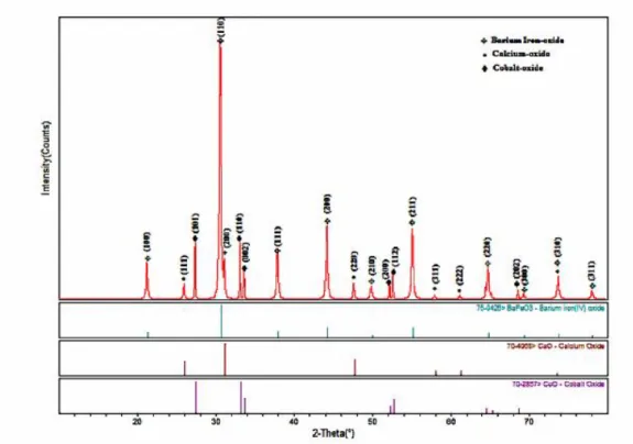
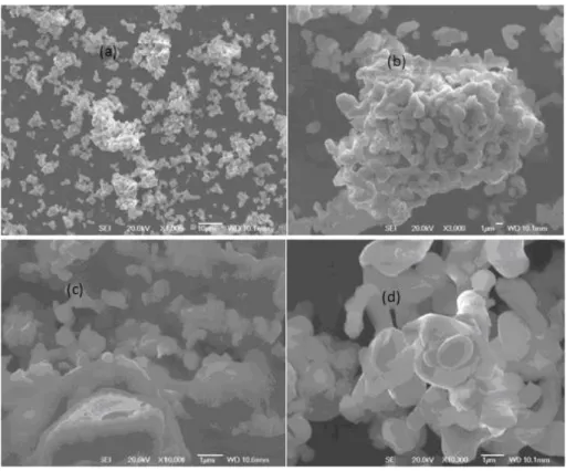
First part of the thesis consists of the work on conventional SOFC to build knowledge and bridge from conventional SOFC to the new EFFC. Novel composite electrode (semiconductor) materials are synthesized and studied using established electrochemical and analytical methods such as x-ray diffraction (XRD), scanning electron microscopy (SEM), and thermogravimetric analysis (TGA). The phase structure, morphology and microstructure of the composite electrodes are studied using XRD and SEM, and the weight loss is determined using TGA. An electrical conductivity of up to 143 S/cm of as-prepared material is measured using DC 4 probe method at 550 ºC. An electrolyte, samarium doped ceria (SDC) is synthesized to fabricate a conventional three component SOFC device. The maximum power density of 325 mW/cm2 achieved from the conventional device at 550 ºC.
In the second part of the thesis, semiconductor-ionic materials based on perovskite and composite materials are prepared for low temperature SOFC and EFFC devices. Semiconductor-ionic materials are prepared via nanocomposite approach based on two-phase semiconductor electrode and ionic electrolyte. This semiconductor-ionic functional component was shown to integrate all fuel cell components anode, electrolyte and cathode functions into a single component, i.e. “three in one”, resulting in enhanced catalytic activity and improved SOFC performance.
The third part of the thesis addresses the development and optimization of the EFFC technologies by studying the Schottky junction mechanism in such semiconductor-ionic type devices. Perovskite and functional nanocomposites (semiconductor-semiconductor-ionic materials) are developed for EFFC devices. Materials characterizations are performed using a number of standard experimental and analytical techniques. Maximum power densities from 600 mW/cm2 up to 800 mW/cm2 have been achieved at 600 ºC.
Fourth part of the thesis describes the theoretical simulation of EFFCs. In this work, an updated numerical model is applied in order to study the EFFC device, which introduces some modifications to the existing relations for traditional fuel cell models. The simulated V-I and P-I curves have been compared with experimental curves, and both types of curves show a good consistency.
ii
Keywords: Semiconductor-ionic materials; electrolyte-layer free fuel cell; low
temperature solid oxide fuel cell; fuel to electricity conversion; Schottky junction; theoretical and experimental curves
iii
Sammanfattning
Bränsleceller av typen fastoxid (SOFC) anses vara en attraktiv kandidat för energiomvandling bland bränsleceller (FC) beroende på flera fördelar som bl.a. miljövänlighet, användning av icke-ädla material och deras bränsleflexibilitet. På grund av hög driftstemperatur står dock konventionella SOFC inför många utmaningar. Bland dessa finns höga drifts- och kapitalkostnader samt det begränsade urvalet av FC-material och relaterade kompatibilitetsproblem. En trend inom SOFC-forskning är inriktning på hur man sänker driftstemperaturen åtminstone till 700 ºC eller lägre. Undersökning av nya elektrolyt- och elektrodmaterial som kan fungera bra vid låga temperaturer är en mödosam väg för att sänka SOFCs arbetstemperatur. Som alternativ finns halvledande-jonledande material som är baserade på perovskit/komposit- och jonledande material. Dessa är potentiella kandidater att arbeta i ett lågt temperaturområde med tillräckliga SOFC-prestanda.
Denna forskning fokuserar på utveckling av halvledar-joniska material för lågtemperatur-solid oxid bränsleceller och elektrolytskikt-fria bränsleceller (EFFC). Detta arbete är indelat i fyra delar:
Den första delen av avhandlingen handlar om arbetet med konventionell SOFC för att bygga kunskap och att överbrygga från konventionell SOFC till det nya EFFC. Nya halvledande kompositelektrodmaterial syntetiseras och studeras med hjälp av etablerade elektrokemiska och analytiska metoder, såsom röntgendiffraktion (XRD), scanning-elektronmikroskopi (SEM) och termogravimetrisk analys (TGA). Fasstrukturen, morfologin och mikrostrukturen hos kompositelektroderna studeras med användning av XRD och SEM, och viktminskningen bestäms med användning av TGA. En elektrisk ledningsförmåga på 143 S/cm av sådant framställt material har uppmätts med användning av DC 4-sond-metoden vid 550 ºC. En elektrolyt, Samarium-dopad Ceriumoxid (SDC) syntetiseras för att tillverka en konventionell SOFC-enhet baserad på tre komponenter. En maximal effekttäthet på 325 mW/cm2
har uppnåtts från den konventionella enheten vid 550 ºC.
I andra delen av avhandlingen är halvledarjoniska material baserade på perovskit och kompositmaterial förberedda för SOFC- och EFFC-enheter med låg temperatur. Halvledar-joniska material har konstruerats genom att skapa en komposit av nano-partiklar (nanokomposit) baserat på halvledarelektrod och elektrolyt i olika kristallina faser som kombineras i en tvåfas-struktur. Denna halvledar-joniska funktionella komponent har visats integrera alla anod-, elektrolyt- och katodfunktioner i bränslecellkomponenterna i en enda komponent, dvs "tre i en", vilket resulterade i förbättrad katalytisk aktivitet och förbättrad SOFC-prestanda.
Tredje delen av avhandlingen tar upp utvecklingen och optimeringen av EFFC-tekniken genom att studera Schottky-kopplingsmekanismen i sådana anordningar av halvledar-jonisk typ. Perovskit och funktionella nanokompositer (halvledar-joniska material) har utvecklats för EFFC-enheter. Materialkarakteriseringar utförs med användning av ett antal standardiserade experimentella och analytiska metoder. En maximal effekttäthet från 600 mW/cm2 upp till och 800 mW/cm2 har uppnåtts vid 600
ºC.
Den fjärde delen av avhandlingen beskriver den teoretiska simuleringen av EFFCs. I detta arbete tillämpas en uppdaterad numerisk modell för att studera EFFC-enheten som introducerar vissa modifieringar av de rådande sambanden i traditionella
iv
bränslecellsmodeller. De simulerade V-I- och P-I-kurvorna har jämförts med experimentella kurvor, och båda typerna av kurvor visar god samstämmighet.
Nyckelord: Halvledar-joniska material; elektrolytskikt-fri bränslecell; lågtemperatur
fastoxidbränslecell; bränsle till elomvandling; Schottky junction; teoretiska och experimentella kurvor
v
‘‘Seek knowledge from cradle to the grave’’
vi
To raise new questions, new possibilities, to regard old problems from a new angle, requires creative imagination and marks real advance in science.
vii
Preface
This doctoral thesis reveals the outcomes of a PhD project conducted on materials using in fuel cells, at Department of Energy Technology, KTH Royal Institute of Technology, Stockholm, Sweden. This work includes eight published journal articles. The work presented consists of investigation of semiconductor-ionic materials, their synthesis, fabrication of solid oxide fuel cells with and without electrolyte-layer, characterization of the materials and the devices, fuel cell testing at low temperatures (up to 600 oC) and theoretical methods and validation of the experimental results.
Semiconductor- ionic composites based on perovskite, composite, nanocomposite and ion conducting materials are found potential candidates for energy conversion applications. Finally, conclusions have been drawn through above study and future work is also proposed to use these outcomes in fuel cell practical applications.
viii
Acknowledgements
All praises to Allah (SWT), the most Beneficent, and the most Merciful. He is the Lord of the whole universe. He has created everything in a very systematic and ordered manner. It is great honor for me to be associated spiritually with our beloved Holy Prophet Hazrat Muhammad (PBUH) (for everlasting support in my life), Ehl-e-bait (the family of Prophet) and Companions of Prophet; they spread goodness, peace and education throughout the world.
Firstly, I would like to acknowledge the financial support provided by KTH Royal Institute of Technology and EC FP 7 TriSOFC project grant for completing my doctoral studies at KTH, Stockholm. I would also like to express my sincere gratitude to my principal supervisor Professor Andrew Martin for his well-determined supervision, guidance and invaluable support throughout my research work. His enlightened and optimistic approach has helped me for smooth completion of my PhD studies. He has significantly improved my way of thinking in research. I am extremely happy for all support from his end.
I would like to express my profound gratitude to my former principal supervisor Professor Bin Zhu who provided me very active supervision and guidance during my doctoral studies and for his significant support for my active research work. He has always given me positive feedback in the research activities whenever I requested his response. He provided me a lot of confidence and respect for projects and Fuel Cell Group management. During every meeting, we had very positive and active discussion about research gaps and new research ideas to solve them. I am also grateful to my co-supervisor Professor Peter Lund from Aalto University, Finland for his support throughout my research work and for the revision of my dissertation.
I would like to express my gratitude to previous co-supervisor Professor Torsten Fransson for his help and guidance during my studies.
A bundle of thanks to my colleagues in Fuel Cell Group, Chen Xia and Yanyan Liu for their unforgettable cooperation and pleasant atmosphere in my office. I wish you good luck for future endeavors in your lives. Moreover, my heartfelt gratitude to Professor Björn Laumert, Peter Hagström, Hatef Madani and Mahrokh Samavati for their critical feedback and suggestions to improve this dissertation. Particularly, thanks to the advance reviewer of my PhD Thesis Professor Göran Lindbergh for his constructive criticism and positive feedback to improve the thesis. I would also like to thank Jan Wikander (Dean of ITM), Malin Selleby (Director of doctoral studies) and my other colleagues at the Department of Energy Technology: Prof. Björn Palm, Rahmatollah Khodabandeh, Jeevan Jayasuriya, Thomas Nordgreen, Justin Chiu, Miroslav Petrov, Chamindie Senaratne, Mauricio, Tobias, Nenad, Rafael, Tony Chapman, Anneli Ylitalo-Qvarfordt, Hamayun Maqbool, Shahid Siyal, Youssef Almulla, Imtisal-e-Noor, Getnet, Wujun Wang (for friendly advices), Taras, Jhonny and other friends at the department for providing me a helping and friendly workplace environment. Particularly, my special thanks to Jens Fridh, Leif Pettersson and Göran Arntyr for their technical support in my experiments throughout my research work.
I would like to acknowledge the support of my previous teachers Sir Ghulam Qadir Jhamat, Professor Muhammet Toprak, Professor Yasir Jameel, Prof. Anders Malmquist
ix
(for Swedish revision) and Professor Per Lundqvist who always encouraged my research capabilities. They always guided me how to reach at the highest level of successes. Thanks to Syed Ijaz Husain Shah Saheb (Hujra Shah Mukeem) for spiritual guidance, prayers, and appreciating me for doing PhD. I would like to pay my regards to my research collaborators and supporters Professor Amir Rashid, Dawood Akhtar, Dr. Jung-Sik Kim, Professor Mikael Syväjärvi, Professor Lyuba Belova, Professor Weihong Yang, Rizwan Raza, Dr. Kaleem Iqbal, Ehsan Baig, Dr. Muhammad Tufail, Mohsin Saleemi, Nasar Ali, Imran Asghar, Professor Naveed Kausar Janjua, Professor Asghar Hashmi, Amjad Ali, Liangdong Fan, Baoyuan Wang, Abdul Malik Tahir, Xiaodi Wang, Ying Ma, Yunjuan He, Muhammad Usman, Muhammad Kamran and other friends for always cooperation regarding research activities. Thanks to Sushant Madaan for theoretical simulations and modelling work.
Thanks to my friends and community representatives Shafqat Khatana, Rahmat Ali, Ali Lashari, Imam Muhammad Muslim, Khalid Yazdani, Asif Butt, Amer Nadeem, Dr. Ghulam Husain, Arif Kisana, Qazi Masood, Ghulam Rasool (for motivation to study in Sweden), Muhammad Sarwar, Riaz Akhtar, Adeel Anwar, Imran Cheema, Waseem Aslam, Tahir Shah, Zulfiqar Husain Shah, Kashif Bhutta, Waqar-ul-Hasan, Hamad, Sadiq, Zazy Khan, Sohail Ahmad, Amir Riaz, Aslan, Nawaz Ahmad, Ali Butt, Saud, Rajjab Ali, Ahsin, Abdullah Khan, Qaiser Waheed, Muhammad Adnan, Nasir Nawaz, Taha Ali, Hasan, Hafiz Qadeer, Musa Kazim Shah, Aqil Khan and many other friends for their moral support throughout my stay in Sweden.
I would like to acknowledge my great mother Hafeezan Bibi (Late) for her endless financial support, teachings, training, guidance and uncountable prayers for my successes throughout my life. I also thank to my spiritual mother Hazrat Fatimah-Tul-Zahra (SA) for spiritual support throughout my life. Thanks to my father, Chaudhary Muhammad Yaqoob (Late) and my grandfathers Chaudhary Muhammad Nazir Lumberdar (Late) and Chaudhary Muhammad Siddique (Late) who gave me a lot of love and knowledge during my early childhood. Thanks to my father-in-law Muhammad Shafique (Late) and my nephew Chaudhary Khurram Shazad (Late) for their moral support during their lives.
I would like to extend my deepest thanks to my sisters and brothers, Chaudhary Muhammad Munawar Faizi, Chaudhary Muhammad Aslam, Chaudhary Muhammad Akram Advocate and Chaudhary Muhammad Arshad for their help, financial support and affectionate love throughout my life. I also thank to my other family members, Chaudhary Muhammad Anwar, Chaudhary Intzar Hussain, Chaudhary Tariq Tabassum and my mother-in-law for their prayers and appreciations.
Last but not the least, I have shortage of adequate words to thank my beloved wife, Anela Afzal for her endless support and love, who always supported me for project meetings and international conferences out of Sweden, prayed for my successes and for taking care of my lovely kids.
Finally, I would like to extend my sweet love and affiliation to my lovely children, ‘‘Atal
Afzal and Huda Afzal’’. I dedicate my research work to my great mother, father and
x
Publications included in dissertation
This doctoral thesis is based on the following eight publications. All of these publications are also appended at the end of this thesis.
1. Muhammad Afzal, Rizwan Raza, Shangfeng Du, Raquel Bohn Lima, Bin
Zhu, Synthesis of Ba0.3Ca0.7Co0.8Fe0.2O3-δ composite material as novel
catalytic cathode for ceria-carbonate electrolyte fuel cells, Electrochimica Acta, Volume 178, 2015, Pages 385-391.
2. Muhammad Afzal, Chen Xia, Bin Zhu, Lanthanum-doped Calcium
Manganite (La0.1Ca0.9MnO3) Cathode for Advanced Solid Oxide Fuel Cell
(SOFC), Materials Today: Proceedings, Volume 3, Issue 8, 2016, Pages 2698-2706.
3. Xunying Wang, Muhammad Afzal, Hui Deng, Wenjing Dong, Baoyuan
Wang, Youquan Mi, Zhaoyun Xu, Wei Zhang, Chu Feng, Zhaoqing Wang, Yan Wu, Bin Zhu, La0.1SrxCa0.9-xMnO3-δ -Sm0.2Ce0.8O1.9 composite material
for novel low temperature solid oxide fuel cells. International Journal of Hydrogen Energy, Volume 42, Issue 27, 2017, Pages 17552-17558.
4. Muhammad Afzal, Mohsin Saleemi, Baoyuan Wang, Chen Xia, Yunjuan
He, Jeevan Jayasuriya, Bin Zhu, Fabrication of novel electrolyte-layer free fuel cell with semi-ionic conductor (Ba0.5Sr0.5Co0.8Fe0.2O3-δ-Sm0.2Ce0.8O1.9)
and Schottky barrier, Journal of Power Sources, Volume 328, 2016, Pages 136-142.
5. Bin Zhu, Peter Lund, Rizwan Raza, Ying Ma, Liangdong Fan, Muhammad Afzal, Janne Patakangas, Yunjun He, Yufeng Zhao, Wenyi Tan, Qiu-An Huang,
Jun Zhang, and Hao Wang, Schottky junction effect on high performance fuel cells based on nanocomposite materials, Advanced Energy Materials, Volume 5, 2015, Pages 1-6.
6. Baoyuan Wang, Yixiao Cai, Chen Xia, Jung-Sik Kim, Yanyan Liu, Wenjing
Dong, Mikael Karlsson, Hao Wang, Muhammad Afzal, Junjiao Li, Rizwan Raza, Bin Zhu, Semiconductor-ionic membrane of LaSrCoFe-oxide-doped Ceria Solid Oxide fuel cells. Electrochimica Acta, Volume 248, 2017, Pages 496-504.
7. Muhammad Afzal, Sushant Madaan, Wenjing Dong, Rizwan Raza, Chen
Xia, Bin Zhu, Analysis of a perovskite-ceria functional layer-based solid oxide fuel cell. International Journal of Hydrogen Energy, Volume 42, Issue 27, 2017, Pages 17536-17543.
8. Yuzheng Lu, Muhammad Afzal, Bin Zhu, Baoyuan Wang, Jun Wang, Chen
xi
Multifunctional Materials at Low Temperatures, Recent Patents on Nanotechnology, Volume 11, Issue 2, 2017, Pages 85-92.
Publications not included in dissertation
9. Zheng Qiao, Chen Xia, Yixiao Cai, Muhammad Afzal, Hao Wang, Jinli Qiao,
Bin Zhu, Electrochemical and electrical properties of doped CeO2-ZnO
composite for low-temperature solid oxide fuel cell applications. Journal of Power Sources, Volume 392, 2018, Pages 33-40.
10. Youquan Mi, Chen Xia, Bin Zhu, Rizwan Raza, Muhammad Afzal, Ilan Riess,
Experimental and physical approaches on a novel semiconducting-ionic membrane fuel cell, International Journal of Hydrogen Energy, in Press, 2018.
11. Amjad Ali, Farrukh Shehzad Bashir, Rizwan Raza, Asia Rafique,
Muhammad Kaleem Ullah, Muhammad Afzal, Moinuddin Ghauri, Lyubov M Belova, Electrochemical study of composite materials for coal-based direct carbon fuel cell, International Journal of Hydrogen Energy, in Press, 2018.
12. Yanyan Liu, Yuanjing Meng, Wei Zhang, Baoyuan Wang, Afzal
Muhammad, Chen Xia, Bin Zhu, Industrial grade rare-earth triple-doped
ceria applied for advanced low-temperature electrolyte layer-free fuel cells. International Journal of Hydrogen Energy, Volume 42, Issue 34, 2017, Pages 22273-22279.
13. Yanyan Liu, Yan Wu, Wei Zhang, Jing Zhang, Baoyuan Wang, Chen Xia,
Muhammad Afzal, Junjiao Li,Manish Singh and Bin Zhu, Natural CuFe2O4
Mineral for Solid Oxide Fuel Cells. International Journal of Hydrogen Energy, Volume 42, Issue 27, 2017, Pages 17514-17521.
14. Yanyan Liu, Wei Zhang, Baoyuan Wang, Muhammad Afzal, Chen Xia, Bin
Zhu, Industrial Grade LaCe1.85Pr0.03Nd0.06Ox/Na2CO3 Nanocomposite for
Novel Low-Temperature Semiconductor-ionic Membrane Fuel Cell. Advanced Materials Letters, Volume 8, Issue 4, 2017, Pages 346-351.
15. Chen Xia, Baoyuan Wang, Yixiao Cai, Wei Zhang, Muhammad Afzal, Bin
Zhu, Electrochemical properties of LaCePr-oxide/K2WO4 composite
electrolyte for low-temperature SOFCs. Electrochemistry Communications, Volume 77, 2017, Pages 44-48.
16. Chen Xia, Muhammad Afzal, Baoyuan Wang, Aslan Soltaninazarlou, Wei
Zhang, Yixiao Cai, Bin Zhu. Mixed-conductive membrane composed of natural hematite and Ni0.8Co0.15Al0.05LiO2-δ for electrolyte layer-free fuel cell. Advanced
xii
17. Chen Xia, Yixiao Cai, Baoyuan Wang, Muhammad Afzal, Wei Zhang, Aslan
Soltaninazarlou, Bin Zhu. Strategy Towards Cost-Effective Low-Temperature Solid Oxide Fuel Cells: A Mixed-conductive Membrane Comprised of Natural Minerals and Perovskite Oxide. Journal of Power Sources, Volume 342, 2017, Pages 779-786.
18. Baoyuan Wang, Yixiao Cai, Chen Xia, Yanyan Liu, Afzal Muhammad, Hao
Wang, Bin Zhu, CoFeZrAl-oxide based composite for advanced solid oxide fuel cells, Electrochemistry Communications, Volume 73, 2016, Pages 15-19.
19. Baoyuan Wang, Yixiao Cai, Wenjing Dong, Chen Xia, Wei Zhang, Yanyan
Liu, Muhammad Afzal, Hao Wang, Bin Zhu, Photovoltaic properties of LixCo3-xO4/TiO2 heterojunction solar cells with high open-circuit voltage,
Solar Energy Materials and Solar Cells, Volume 157, 2016, Pages 126-133.
20. Bin Zhu, Liangdong Fan, Hui Deng, Yunjuan He, Muhammad Afzal,
Wenjing Dong, AZRA YAQUB, Naveed K. Janjua, LiNiFe-based layered structure oxide and composite for advanced single layer fuel cells, Journal of Power Sources, Volume 316, 2016, Pages 37-43.
21. Wenjing Dong, Azra Yaqub, Naveed K. Janjua, Rizwan Raza, Muhammad
Afzal, Bin Zhu, All in One Multifunctional Perovskite Material for Next
Generation SOFC, Electrochimica Acta, Volume 193, 2016, Pages 225-230.
22. Chen Xia, Baoyuan Wang, Ying Ma, Yixiao Cai, Muhammad Afzal, Yanyan
Liu, Yunjuan He, Wei Zhang, Wenjing Dong, Junjiao Li, Bin Zhu, Industrial-grade rare-earth and perovskite oxide for high-performance electrolyte layer-free fuel cell, Journal of Power Sources, Volume 307, 2016, Pages 270-279.
23. Yunjuan He, Liangdong Fan, Muhammad Afzal, Manish Singh, Wei
Zhang, Yufeng Zhao, Junjiao Li, Bin Zhu, Cobalt oxides coated commercial Ba0.5Sr0.5Co0.8Fe0.2O3−δ as high performance cathode for low-temperature
SOFCs, Electrochimica Acta, Volume 191, 2016, Pages 223-229.
24. Bin Zhu, Yizhong Huang, Liangdong Fan, Ying Ma, Baoyuan Wang, Chen
Xia, Muhammad Afzal, Bowei Zhang, Wenjing Dong, Hao Wang, Peter D. Lund, Novel fuel cell with nanocomposite functional layer designed by perovskite solar cell principle, Nano Energy, Volume 19, 2016, Pages 156-164.
25. Huiqing Hu, Qizhao Lin, Zhigang Zhu, Xiangrong Liu, Muhammad Afzal,
Yunjuan He, Bin Zhu, Effects of Composition on the Electrochemical Property and Cell Performance of Single Layer Fuel Cell, J. Power Sources, Volume 275, 2015, Pages 476-482.
xiii
26. Huiqing Hu, Qizhao Lin, Afzal Muhammad, Bin Zhu, Electrochemical
study of lithiated transition metal oxide composite for single layer fuel cell, J. Power Sources, Volume 286, 2015, Pages 388-393.
27. Liangdong Fan, Muhammad Afzal, Chuanxin He, Bin Zhu, 12:
Nanocomposites for “nano green energy” applications. Bioenergy Systems for the Future, 2017, Pages 421-449.
28. Rizwan Raza, Muhammad Kaleem Ullah, Muhammad Afzal, Asia Rafique,
Amjad Ali, Sarfraz Arshad, Bin Zhu, 15: Low-temperature solid oxide fuel cells with bioalcohol fuels. Bioenergy Systems for the Future, 2017, Pages 521-539.
xv
Table of Contents
Abstract ... i
Sammanfattning ... iii
Preface ... vii
Acknowledgements ... viii
Publications included in dissertation ... x
INDEX OF FIGURES ... xvii
INDEX OF TABLES ... xix
NOMENCLATURE ... xxi
Acronyms & Abbreviations ... xxi
Symbols ... xxii
1 INTRODUCTION ... 1
1.1 Solid Oxide Fuel Cell (SOFC) ... 2
1.2 Structures of SOFC ... 3
1.3 Perovskite Materials in SOFC ... 7
1.4 Thermodynamics of SOFC and EFFC ... 8
1.5 Nanocomposite Approach ... 9
1.6 Objectives and methodology ... 10
1.7 Limitations ... 11
1.8 Thesis outline ... 12
2
SUMMARY OF APPENDED PUBLICATIONS ... 13
3
THEORY ... 17
3.1 Nanotechnology Based SOFCs with Multifunctional Materials at Low Temperatures (Paper 8) ... 18
3.2 Multi-functional Nanocomposite and Semiconductor-ionic Materials for Electrolyte-layer Free Fuel Cell ... 19
3.3 Patents in Electrolyte-layer Free Fuel Cells with Nanotechnology ... 19
3.4 Theoretical Studies and Modeling (Paper 7) ... 20
3.4.1 From Low Temperature Solid Oxide Fuel Cell to Electrolyte-layer Free Fuel Cell 20 3.4.2 Adopted updated model for EFFC ... 20
3.4.3 Electrode kinetics ... 21
3.4.4 Reaction thermodynamics ... 21
3.4.5 Voltage losses ... 22
4
METHODS AND MATERIALS ... 25
4.1 Electrode/Semiconductor Materials Synthesis for LTSOFC/EFFC ... 25
4.1.1 Synthesis of Novel Ba0.3Ca0.7Co0.8Fe0.2O3-δ (BCCF) Composite Material (Paper 1) 25 4.1.2 Synthesis of lanthanum-doped calcium manganite (La0.1Ca0.9MnO3) (LCM) cathode material (Paper 2) ... 26
xvi
4.2 Electrolyte/ionic materials synthesis for LTSOFC/EFFC ... 29
4.2.1 Preparation of samarium doped ceria Sm0.2Ce0.8O2-δ (SDC) (Paper 2) ... 29
4.3 Semiconductor-ionic materials for EFFC ... 30
4.4 Components and fuel cell fabrication ... 30
4.5 Characterization Methods ... 32
4.6 Fuel Cell Testing Facility ... 32
5
RESULTS AND DISCUSSION ... 35
5.1 Conventional SOFC using BCCF as Cathode Material (Paper 1) ... 35
5.1.1 Structural Analysis and Morphology ... 35
5.1.2 FTIR and TGA Analyses ... 37
5.1.3 Conductivity Measurement ... 37
5.1.4 BCCF cathode in SOFC Performance ... 38
5.2 EFFC and LTSOFC Devices using Semiconductor-ionic Materials (Papers 2 & 3) 39 5.2.1 Structural Analysis and Microstructure of LCM and SDC-LCM Composite (Paper 2) ... 39
5.2.2 ORR Activity of LCM in LTSOFC Configuration ... 41
5.2.3 Performance of LCM Cathode ... 42
5.2.4 Devices Based on Modifications in LCM Material (Paper 3) ... 43
5.3 EFFC Schottky Junction Effect (Papers 4, 5 & 6) ... 43
5.3.1 Crystal Structure and Microstructure of BSCF (Paper 4) ... 43
5.3.2 Electrochemical Properties ... 44
5.3.3 Electrical Conductivity Measurements ... 46
5.3.4 Fuel Cell Performance ... 46
5.3.5 Schottky Junction Effect in EFFC ... 47
5.3.6 Schottky Junction Effect in EFFC (Paper 6) ... 48
5.4 Comparison of Theoretical and Experimental Results (Paper 7) ... 50
5.4.1 Comparison of Modelling and Experimental approaches ... 50
6
CONCLUSIONS AND FUTURE WORK ... 53
6.1 Conclusions ... 53
6.2 Future Work ... 55
7
REFERENCES ... 57
xvii
INDEX OF FIGURES
Figure 1: Working principle of fuel cell. ……….2
Figure 2: SOFC configuration (a) 3-component device (b) 2-components device (c) Single component device. ………...4
Figure 3: Comparison of a conventional SOFC and single component EFFC. ……...5
Figure 4: a) A fuel cell device assembled by n-type conducting anodic regime, ionic electrolyte and p-type conducting cathode. b) Removal of the electrolyte-layer in between, the new device is an n-p junction assembly. [40] ………..6
Figure 5: Nano redox process at particle level in the EFFC. ………..6
Figure 6: Elements that can occupy sites in ABO3 perovskite structure (based on [47]).8 Figure 7: Schematic of SOFC MEA system with interconnects design. ………17
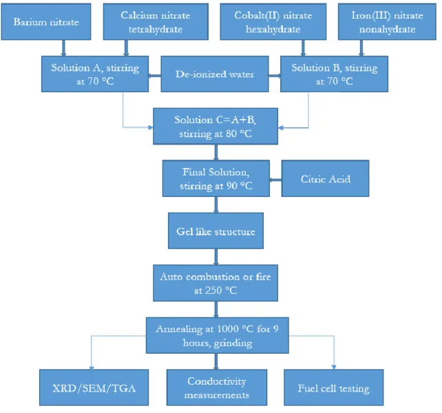
Figure 8: Flow chart for synthesis of novel BCCF material. ……….26
Figure 9: Flow chart for synthesis of LCM material. ………27
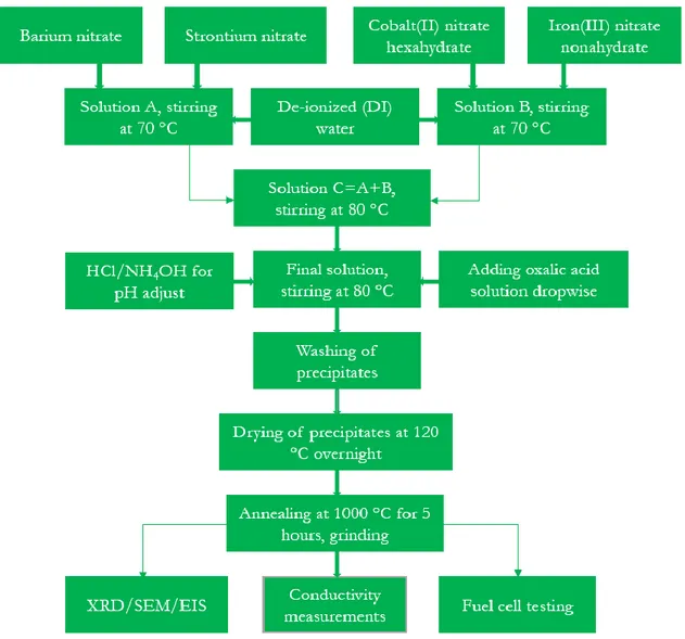
Figure 10: Flow chart for preparation of perovskite BSCF material. ………....28
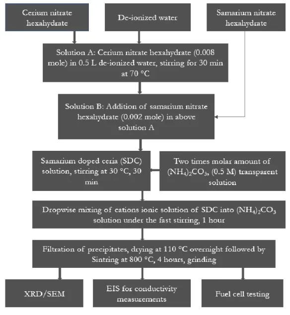
Figure 11: Flow chart for synthesis of SDC material. ………...29
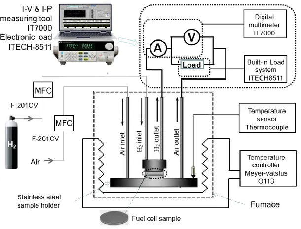
Figure 12: Fuel cell testing setup. ……….33
Figure 13: XRD pattern of BCCF. ………...35
Figure 14: SEM images of BCCF37 (a-c) and BCCF91 (d). (Paper 1) ………...36
Figure 15: (a) FTIR and (b) TGA analyses. (Paper 1) ……….……..37
Figure 16: Conductivity vs temperature for sample Ba0.3Ca0.7Co0.8Fe0.2O3-δ (BCCF)……….38
Figure 17: Fuel cell performance (3-layers) ………...39
Figure 18: XRD patterns of Perovskite LCM, 6SDC-4LCM at lower temperatures and 6SDC-4LCM at 750 oC. ………40
Figure 19: SEM images of high temperature sintered LCM. ………..40
xviii
Figure 21: V-I and P-I characteristics of the SOFCs and EFFC at 550 oC. …………42
Figure 22: XRD diffraction pattern of as-prepared BSCF. (Paper 4) ……….44 Figure 23: (a & b) SEM images of BSCF. ……….44 Figure 24: EIS measurements for three layer fuel cell (a) and single layer fuel cell (b), the data points are the measured data and the solid line are the fitting results. The inset is the equivalent circuit for simulations. The curves (C) give the Bode plots for the two kinds of fuel cells. ……….45 Figure 25: Temperature dependence of conductivity for lab made and commercial BSCF………46 Figure 26: Fuel cell performance for 3-layer FC and EFFC at 550 ⁰C. (Paper 4) ……47 Figure 27: Schematic of post SEM micrograph of electrolyte-layer free fuel cell (EFFC)……….48 Figure 28: Structure of fuel cell with Schottky junction formation. (Paper 6) ……...49 Figure 29: Diode effect measurement (a) in air (b) in FC conditions. ………....49 Figure 30: Electrochemical impedance measurement of EFFC at different temperatures and equivalent circuit. (Paper 7) ………....50 Figure 31: Comparison of theoretical and experimental V-I and P-I characteristics...51 Figure 32: V-I characteristics with fixing (a) m and (b) n values as constant. ……….52 Figure A-1: Old gas flow controller for hydrogen used for initial experiments. …….65 Figure A-2: Fuel cell performances with new gas flow controllers. ………....66
xix
INDEX OF TABLES
xxi
NOMENCLATURE
Acronyms & Abbreviations
ABO3 Structural formula of perovskite oxides
AC Alternating current
AFC Alkaline fuel cell
ASOFC Advanced solid oxide fuel cell
ASR Area specific resistance
BCCF BaXCa1-XCoYFe1-YO3-δ
BCCF37 Ba0.3Ca0.7Co0.8Fe0.2O3-δ
BCCF91 Ba0.9Ca0.1Co0.8Fe0.2O3-δ
BHJ Bulk heterojunction
BSCF BaxSr1-xCoyFe1-yO3-δ (e.g. Ba0.5Sr0.5Co0.8Fe0.2O3-δ)
CPE Constant phase element
CSDC Calcium and samarium co-doped ceria
DC Direct current
DMFC Direct methanol fuel cell
EDX Energy dispersive X-ray
EDS Energy dispersive X-ray spectrometer
EFFC Electrolyte-layer free fuel cell
EIS Electrochemical impedance spectroscopy
EMF Electromotive force
FC Fuel cell
FTIR Fourier transform infrared spectroscopy
GDC Gadolinium doped ceria
HCl Hydrochloric acid HHV Higher heating value
HOR Hydrogen oxidation reaction
HRTEM High-resolution transmission electron microscopy
HTSOFC High-temperature solid oxide fuel cell
IEA International energy agency
ITSOFC Intermediate-temperature solid oxide fuel cell
LCM La0.1Ca0.9MnO3
LiAlO2 Lithium Aluminum oxide
LN-SDC Sm0.2Ce0.8O1.9 - LiNaCO3
LNZ LiNiZn oxide
LSCF La1-xSrxCo1-yFeyO3- δ
LSCM La0.1SrxCa0.9-xMnO3-δ
LSM La1-xSrxMnO3
LTSOFC Low temperature solid oxide fuel cell
MCFC Molten carbonate fuel cell
MEA Membrane electrode assembly
MFC Mass flow controllers
xxii
NCAL Ni0.8Co0.15Al0.05LiO2
NH4OH Ammonium hydroxide
(NH4)2CO3 Ammonium carbonate
Ni Nickel
NiO Nickel oxide
NSDC Sm0.2Ce0.8O1.9 - Na2CO3
OCV Open circuit voltage
ORR Oxygen reduction reaction
PAFC Phosphoric acid fuel cell
PEMFC Proton exchange (or polymer electrolyte) membrane fuel cell
P-I Power density vs current density R&D Research and development SCDC Sm/Ca co-doped ceria
SDC Samarium doped ceria
SEM Scanning electron microscopy
SIC Super-ionic conduction
SIFCs Semiconductor-ionic fuel cells
SIM Semiconductor-ionic material
SLFC Single layer fuel cell
SOFC Solid oxide fuel cell
SrTiO3 Strontium titanate
SSC Sm0.5Sr0.5CoO3
SSZ Scandia-stabilized zirconia
STP Standard temperature and pressure
TEM Transmission electron microscopy
TGA Thermo-gravimetric analysis
TPB Triple phase boundary
TPM Two phase materials
UN United Nations
V-I Voltage vs current density
XRD X-ray diffraction
YSZ Yttrium stabilized zirconia
Symbols
C Concentration at the electrode surface
Ca Calcium Co Cobalt °C Degree Celsius cm Centimeter CO Carbon monoxide CO2 Carbon dioxide (CO3)2- Carbonate
Cp Specific heat at constant pressure, in J K-1 kg-1
xxiii
e.g. For example
E EMF or open circuit voltage
E° EMF at STP, and with pure reactants (standard cell potential)
Erev Reversible (Nernst) potential
Ecell Cell voltage
F Faraday’s constant, the charge on one mole of electrons, 96485 C mol-1
∆G Change in actual free energy
G Gibbs free energy (or negative thermodynamic potential)
ΔGf Gibbs free energy (Gf) for overall cell reaction
Gf (Products) Gibbs free energy for the products
Gf (Reactants) Gibbs free energy for the reactants
(Gfm)H2O Molar specific Gibbs free energy of formation in case of water
g Gibbs free energy per mole
h Electronic hole
hf Enthalpy of formation
H+ Proton
H2 Hydrogen gas
H2O Water
I Current, current density
i Current density, current per unit area
io Peak exchange current density
i.e. That is
KOH Potassium hydroxide
m Constant (with units of Volt) which depends on the inside conditions of the FC
mm Millimeter
N Avogadro’s number, 6.022 x 10²³ mol-1 also revolutions per second
n Number of electrons
n Constant (with units of the reciprocal of the current density)
n Number of moles
nm Nanometer O2− Oxygen ion
(OH)- Hydroxyl ion
O2 Oxygen gas
P Electrical power (mW), also power density (mW/cm2)
PH2 Partial pressure of hydrogen
PO2 Partial pressure of oxygen
PH2O Partial pressure of water vapour
R Universal gas constant, 8.314 J mol-1 K-1, also electrical resistance
Rct Charge transfer resistance
Rcta Charge transfer resistivity for anode
Rctc Charge transfer resistivity for cathode
RH High frequency resistance
Ri Internal resistance
RL Low frequency resistance
Rmt Mass transport resistance
xxiv
Scm-1 Siemens per centimeter
sf Entropy of formation
T Working Temperature
t Time
V Voltage
Va Activation over-potential or activation polarization
Vc Concentration loss or the over-potential loss
Vcell Operating cell voltage
Vohm Ohmic loss or ohmic over-potential
We Electrical work
z Number of the electrons transferred % Percentage
& And
ε Efficiency of a fuel cell
α Coefficient for charge transfer, 0.2 < α < 1 (used in the updated model, α is 0.25)
αo Coefficient of transfer for oxidation reaction
1
1 INTRODUCTION
Energy is considered central to almost all major challenges and opportunities the world is facing today. Access to clean and affordable energy is essential for all sectors of society, and is an integral part of most of the 17 Sustainable Development Goals as defined by the UN [1]. To this end, significant progress has been seen during the past several decades in harnessing solar, biomass, and wind energy resources for supplying renewables-based electricity and transportation systems. In parallel, substantial gains are apparent in energy efficiency in the built environment, industry, and transportation. Nonetheless, there is a constant requirement to focus research and development, investments, and policy efforts towards expanding the role of renewable energy sources, and to ensure that they are utilized in the most effective way.
A number of scenarios for a future sustainable energy system with low climate change impact consider hydrogen as an energy carrier. This concept relies upon either water/steam electrolysis from renewables-based electricity or biomass-derived syngas to supply hydrogen, which in turn can be stored or converted further downstream. It is paramount that the involved energy conversion processes are extremely efficient in order to minimize losses from source to end use. In this setting, fuel cells for fuel-to-electricity conversion play a critical role, having inherent advantages of high efficiency, environment friendly, scalability, and good part-load performance [2-4]. As shown in Figure 1, a fuel cell (FC) is comprised of an anode, electrolyte, and cathode, utilizing the electrochemical reaction between hydrogen and oxygen to supply electrons and water.
Since the invention and demonstration by Sir William Grove in 1839 [5], all of the fuel cells have been assembled with a structure based on three components. The type of electrolyte, employed as a key component [6-10], characterizes FC types. For example, the polymer electrolyte or proton exchange membrane fuel cell (PEMFC) uses solid polymer electrolyte and platinum catalyst fixed in porous carbon electrodes. Due to high power density, it is advantageous and favorable as compared to other types of fuel cells. A PEMFC operates at temperatures 50-100 °C with typical mobile application efficiencies of 53-60% and stationary application efficiencies of 25-35% [11-13]. Because of low working temperatures, PEMFCs have fast start-up times and are thus relevant for transport applications [14]. Alkaline fuel cell (AFC) utilizes several non-noble metals as catalyst for the electrode functions. Conventional AFCs operate in a temperature range of 50-200 °C whereas advanced AFCs can operate from 23-70 °C with efficiencies up to 60% [10-15]. Phosphoric acid fuel cell (PAFC) utilizes a phosphoric acid solution contained in e.g. Teflon-bonded silicon carbide matrix as the electrolyte, and porous carbon electrodes contain platinum catalyst [10]. PAFCs operate at temperatures 200-250 °C with an efficiency of about 40% [11-13].
Molten carbonate fuel cell (MCFC) is an intermediate temperature device (600-700 °C) in which molten carbonate salt mixture is used as an electrolyte by filling into porous lithium aluminum oxide (LiAlO2) matrix. However, at the electrodes, non-noble
catalysts can be used. The efficiency of this fuel cell is 45-47% [10-12]. Finally, solid oxide fuel cell uses solid oxide material as an electrolyte. SOFC is a promising fuel cell type because of several advantages (e.g. non-noble materials, fuel flexibility etc.) as
2
compared to other types. A more detailed overview of some key SOFC research and development issues follows.
Figure 1: Working principle of fuel cell.
1.1 Solid Oxide Fuel Cell (SOFC)
SOFCs are not bound to precious noble metal catalyst and therefore are capable for cost reduction by using ceramic materials. Due to the high working temperature, the internal reformation of the fuels is also accessible and due to this property, a variety of fuels can be used in this type of fuel cell without using an external reformer. SOFCs have a capacity to tolerate sulfur and are not poisoned due to CO. This characteristic of SOFC also allows the use of even nonrenewable synthetic gas prepared from the existing coal and can be significantly used in device operation. For a comparison, thermodynamic cycles can operate directly from fossil fuels and can deliver 30-60% efficiency while SOFC can deliver better output using different fuels [16]. However, use of clean fuel sources (e.g. hydrogen gas) is always preferred. It has an efficiency of up to 60%, increasing to as much as 85% with recovery of dissipated heat in addition to electricity [13].
In a solid oxide fuel cell, electrolyte should be sufficiently dense to block gas transport and insulate against electron conduction, while it should be a good ionic conductor. Both of the electrode materials should be porous enough for gas transport and catalytic for reduction, oxidation (redox) reactions and both should be good electrical conductors for electrons. For several decades, the relatively thick layer of electrolyte in conventional technology has introduced large power losses due to high ohmic losses. Operation at elevated temperatures above 700 oC allows the use of carbon monoxide
and hydrocarbons (ethanol, methanol, etc.) in addition to hydrogen, enabling fuel flexibility [12]. Conventionally SOFC is a high temperature technology for which up to 1000 oC is required for the activation of sufficiently high ionic conductivity (0.1 S/cm)
for typical electrolyte such as yttrium stabilized zirconia (YSZ). This restricts the material selection of the FC components (e.g. anode, cathode, interconnects, sealing material), leading to high operational and capital system costs [8-9, 17].
Scientists have used different approaches to minimize the SOFC power losses. First approach in this perspective was applied for the investigation of new materials that could mitigate power losses, leading to better performance. However the range of available materials is limited, and so far YSZ was found to be the most suitable
3
electrolyte for conventional high temperature devices [18, 19]. Second approach was thin film technology, in which scientists attempted to make the electrolyte layer as thin as possible. Some reductions in power losses have been realized through this approach using thin films of electrolyte. However, high associated system costs need to reduce operating temperature to develop cost-effective technology [18], which can be said as the third approach. Reduction of the operating temperature can be achieved by the development of new materials by using composite approach (more details are given in the upcoming sections). According to developments through above three approaches, state of the art SOFCs operate in three ranges of temperature: conventional high temperature; 800-1000 °C; intermediate temperature; 600-800 °C; and low temperature, below 600 °C [19-24]. Today, most of the worldwide SOFC research and development is focused on the development of LTSOFCs because this solves the challenges related to high temperature, which is also the focus of this thesis.
Low temperature operation of the SOFC is ultimately needed for the device stability to avoid material degradation and compatibility issues and in order to maintain the low cost of the system. Since end users are not interested to purchase high temperature technology because of its several times higher price than other available technologies, it is therefore important to focus on the low temperature range to solve the existing challenges. In a seminal article by Goodenough [25], it is proposed that the main solution to avoid drawbacks with high temperature operation is to reduce the working temperature of SOFC by focusing on new materials that should have sufficient ionic conductivity at low temperatures. It has become top research and development (R&D) goal that advanced SOFC should operate in low temperature range 300-600 °C [26-28]. However, extensive worldwide efforts have been made in recent two decades to develop LTSOFC materials (semiconductor, ionic and the composite materials), new alternative electrolyte materials to replace conventional YSZ, but have not yet been available. In this thesis work, initial focus is to develop LTSOFCs including electrolyte-layer free fuel cells (EFFCs) operating below 600 °C and investigation of the useful materials for these devices.
1.2 Structures of SOFC
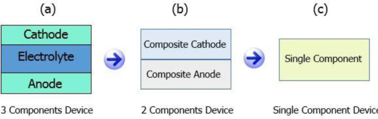
Most recent advances in the technologies included in the discussion above are related to LTSOFCs, which may be divided into three sub-types according to their structures.
i) 3-component device ii) 2-component device iii) Single component device
In conventional 3-component device, solid electrolyte component (layer) is sandwiched between the anode and the cathode components (layers) to obtain an open circuit voltage (OCV) and both electrodes are connected through an external circuit to deliver output power across a load. Research and development work on the electrolyte has been carried out for many decades, but still challenges are not fully solved. In the latest developments, an innovative technology electrolyte-layer free fuel cell (EFFC) was invented in 2010 by Dr. Zhu’s Group at KTH, and was selected as the research highlight on Nature Nanotechnology. Without using an electrolyte-layer, EFFC
4
consists of two components (layers) (composite anode and composite cathode compacted together) and single component that is a homogeneous mixture of semiconductor and ionic materials (e.g. ceria based ion conductors) forming ‘‘three in one’’ structure and similar OCV and power can be obtained as those of conventional 3-component fuel cells. In single component EFFC device, pure electrolyte-layer is not used, however, electrolyte particles are embedded into ‘three in one’ mixture of the single component.
Figure 2: SOFC configuration (a) 3-component device (b) 2-component device (c) Single component device.
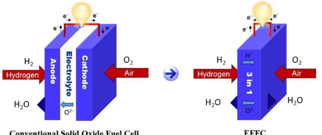
Difference among all three structures is shown in Figure 2. Technically, an EFFC is easy to fabricate and handle because of simpler technology with less layers, and it has shown promising results in the fuel cell conditions. EFFC mechanisms are responsible for the better device performance over conventional SOFC technology in the same operating conditions.
As the conventional YSZ requires operation above 800 °C due to its ionic conductivity limitation, the YSZ electrolyte based SOFC is restricted by the high temperature barrier. Thin film and low temperature materials have improved the technology but still there are issues relating to compatibility and catalytic activity of the electrodes in conventional FCs, like power losses because of the physical barriers between electrodes and the electrolyte and the incompatibilities between the fuel cell components. However, if the electrolyte-layer can be replaced with some novel component, an innovative technology may emerge. Recently, such a technology has been developed that has apparently eliminated the demand of the electrolyte layer, therefore is called an electrolyte-layer free fuel cell (EFFC). A schematic comparison between working principles of conventional SOFC and the EFFC is shown in Figure 3 [28-31].
Previously, the working of EFFC has been presented based on the insufficient knowledge about this innovation during the initial years and could not address the basic questions clearly. In particular, a relevant question how short-circuiting problem was avoided without using any electrolyte-layer in EFFC was not addressed satisfactorily. However, for comprehensive understanding one should keep in mind that electrolyte material particles are embedded into the homogeneous mixture of EFFC material. As a fact, the state of the art SOFC cathode materials based on perovskite oxides themselves are semiconductor materials. The cathode material with semiconducting
5
properties was often ignored or less noticed in SOFCs. The cathode component used for SOFC is usually a homogeneous mixture of the cathode perovskite and ionic electrolyte combined to form a mixed ionic and electronic conducting composite in order to reduce the electrolyte/cathode interface polarization loss [10].
Figure 3: Comparison of a conventional SOFC and single component EFFC. Further looking at the cathode component (when we use it as composite cathode) of SOFC, it is also a type of semiconductor-ionic material that is new kind of functional materials which on one hand can work for semiconducting physical properties to build junctions to prevent the electronic passage, while on the other hand, a medium for ionic transport properties. Introduction of semiconductor-ionic approach by replacement of the electrolyte-layer barrier has led an alternative way to solve the challenges faced for current SOFCs due to poor ionic conductivity of the electrolyte materials at low temperatures. A great enhancement in the ionic conductivity (at least two orders of magnitude) has been achieved in such materials, for example, in a perovskite semiconductor strontium titanate (SrTiO3) and the ionic electrolyte material YSZ
[32-34]. Similar phenomenon has also been found in case of samarium doped ceria (SDC) mixed homogeneously with SrTiO3 [34]. Even, prominent enhancement in the ionic
conductivities has been achieved in these heterostructures of semiconductor-ionic materials, and SOFC device output power is good based on these reported new materials. One of the main reasons could be the strong electronic conductivity in such hybrid structured materials due to the presence of SrTiO3 [35]. According to the
conventional fuel cell science, the electronic conduction through the electrolyte membrane causes serious open circuit voltage (OCV) and electrical power losses [36-39].
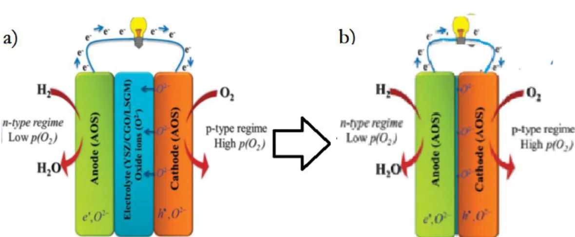
Recently, Singh et al. [40] pointed out that n- and p-type oxide materials can fulfill the requirements of anode and cathode respectively, showing a new scientific view of understanding of SOFC from the physical aspects of semiconductors, as shown in Figure 4. This is a new pathway to understand the FC science from traditional electrochemical cell to new semiconductor-ionic device. Here, anode region is actually an n-type semiconductor and the cathode region, is the p-type. Then an ionic conductor in between them is the electrolyte. Hence, a fuel cell device may be considered as an assembly consisting of n, p and ion conducting materials/components.
6
Figure 4. a) A fuel cell device assembled by n-type conducting anodic regime, ionic electrolyte and p-type conducting cathode. b) Removal of the electrolyte-layer in
between, the new device is an n-p junction assembly. [40]
It can be derived from Figure 4, if we remove the electrolyte component (layer) between the n-anode and p-cathode, the device turns into a n-p junction assembly. Same principle is used in solar cell, i.e. without using the electrolyte layer/component, the device can make no electronic short-circuiting problem due to the presence of junction blocking the electrons, and thus the electrolyte-layer free fuel cell can be one possible structure. There is another mechanism reported for the nano-redox process that takes place in EFFC [41] through bulk heterojunction (BHJ) built on the semiconductor (n- and p-type) material particles in one semiconductor-ionic component of the fuel cell. From this perspective, anode/cathode functions can be completed by n, p and electrolyte ionic transportation through ionic particles as illustrated in Figure 5, thus the FC redox process is occurred at nanoparticle level.
7
For better understanding, we can simply consider to compact from macro SOFC redox to EFFC nanoscale particle level. As mentioned above, by removing the electrolyte-layer between the anode and cathode, the new device turns into an n/p junction device that is a well-known mechanism in solar cell field. The functioning of such device using n and p type semiconductor materials mixed with ion conducting ceria shows the comparable EFFC performance as compared to that of conventional SOFC with anode/electrolyte/cathode configuration. Bi-layer n-p semiconductor-ionic fuel cell is first prototype of such n/p junction device that has been demonstrated recently [42-43]. Following this line, further semiconductor-ionic fuel cells (SIFCs) have been developed to construct EFFC devices with junction type designed according to energy band alignment.
1.3 Perovskite Materials in SOFC
An important issue in reducing the working temperature of the devices is the poor catalytic activity for hydrogen oxidation reaction (HOR) at anode and oxygen reduction reaction (ORR) at cathode, therefore oxidation and reduction of the fuel and oxygen respectively becomes a significant challenge. On the other hand, lower ionic conductivity through electrolyte materials operating at lower temperatures becomes another obstacle. Perovskite oxides with the structure formula ABO3 containing high
mixed electronic and ionic conductivities have attracted much attention in various SOFC concepts. Therefore, a focus on perovskite materials for LTSOFCs and EFFCs development has been considered.
According to the modified periodic table shown in Figure 6, chemical elements can be doped at A or B position of the perovskite structure formula ABO3. The common
anode and cathode material in SOFCs is strontium doped LaMnO3 (LSM). However,
it is not fully suitable due to its poor catalytic activity and low ionic conductivity at intermediate or low temperatures [44]. According to the literature, La0.6Sr0.4Co0.8Fe0.2O3
(LSCF) has been used as a perovskite cathode material for SOFCs at intermediate and low temperatures [45]. Another perovskite oxide, BaxSr1-xCoyFe1-yO3-δ (BSCF) as
cathode material, is seen as an attractive material due to its mixed electronic and ionic conductivity and good catalytic activity especially for the composition Ba0.5Sr0.5Co0.8Fe0.2O3-δ [18, 46] meeting the requirements for perovskite structure [47].
Based on the periodic table for perovskites presented in Figure 6, several new perovskite materials can be designed for energy applications.
8
Figure 6: Elements that can occupy sites in ABO3 perovskite structure (based on [47]).
1.4 Thermodynamics of SOFC and EFFC
SOFC works according to the principles of thermodynamics. When fuel (hydrogen) is fed at the anode and air (oxygen) is supplied at the cathode side, oxidation of fuel/hydrogen takes place at anode (through anode half-cell reaction) and reduction of oxygen occurs at cathode (through cathode half-cell reaction). Simultaneously the electrolyte transports oxide ions from cathode to the anode. During this process, all chemical reactions take place in the cell at certain temperature and water, heat and electricity are generated [19].
Anode half-cell reaction: anode material in case of catalytically active oxidizes
hydrogen molecule to produce water molecule.
H2 + O2- → H2O + 2e- (1.1) Cathode half-cell reaction: oxygen from air is reduced into oxide ions by getting two
electrons for one atom of oxygen at cathode.
½ O2 + 2e- → O2- (1.2) Complete cell reaction: the overall cell reaction can be given as below.
H2 + ½ O2 → H2O + heat + electricity (1.3) Open Circuit Voltage (OCV)
Open circuit voltage (OCV/E) of SOFC is developed between anode and cathode in an open circuit condition. OCV can be calculated by Gibbs free energy relation for ∆G [48].
9
E = - ∆G/nF (1.5)
In case of SOFC as an oxygen concentration cell, OCV can be calculated by Nernst equation [48]. So, EMF (electromotive force) or the reversible voltage (thermodynamically) at the higher temperatures is given as below.
E = E° + (RT
𝐧F) (ln ( P(H2)
P(H2O)) + ln (√P(O2))) (1.6)
OCV (E) depends on operating temperature of fuel cell, concentrations of hydrogen at anode, oxygen at cathode and water at the anode.
Here, ∆G is the change in actual free energy, n is number of electrons which are transferred in the cell reaction, F is Faraday’s constant, E is the electrochemical potential, E° is standard cell potential, R is universal gas constant, T is the working temperature of the cell in kelvin.
Fuel Cell Efficiency
As, fuel cells use some materials which are typically burnt (in an electrochemical way) in order to release the required energy, therefore fuel cell efficiency can be described as a ratio of an electrical energy obtained to the heat produced by burning the fuel (i.e. enthalpy of formation denoted by Δhf).
Efficiency of a fuel cell can be determined from following relation [48].
ε = We/Qin (1.7)
We is electrical work and given by ∆G. From equation (1.4), the quantitative value of
∆G is given by nFE. For the reaction taking place, enthalpy of formation is denoted by Qin. As two values can be calculated depending upon state of reactants therefore higher
of the two values (i.e. higher heating value) is used and is denoted by HHV. Hence equation (1.7) can be written as.
ε = ∆G/Qin = nFE/HHV (1.8) 1.5 Nanocomposite Approach
Nanocomposites for advanced fuel cell technology (NANOCOFC) is an advanced scientific approach to develop semiconductor and ionic functional heterostructure nanocomposite materials for constructing advanced fuel cells at low temperatures (300-600 °C). Synthesized nanocomposites can also be useful in several other electrochemical devices for energy conversion [49-57]. These nanocomposites based on semiconductor-ionic (perovskites-ionic) materials are usually two phase materials (TPMs) which give some unique characteristics as well as multiple functions which are given below [50-55].
i) TPM heterostructures generate interfaces among the particles of two different phases. These two phase interfacial regions (often as a core-shell
10
structure, e.g. NSDC) are supportive for the material functionalities. Compared to the traditionally used single phase bulk doping material, e.g. YSZ, the structural limits have been eliminated due to the interfacial functionalities in semiconductor-ionic materials.
ii) Ion transport in single phase structure, so called “bulk” conduction does not play a viable role in TPM electrolytes and is quite different from conventional single phase bulk structures. Interfacial regions create super-ionic conduction (SIC) paths and therefore promote the functionalities and the electrical properties.
iii) The primary ions (O2-, H+) can rapidly move through the bulk structure and
interfaces and the SIC mechanism enhances the device performance at low temperatures 300-600 °C.
iv) Interfacial SIC mechanisms help to develop new functional materials and make “non-function” to function, e.g. interfaces in insulators.
v) New opportunities for development of advanced LTSOFCs and EFFCs by introducing interfacial and surface redox processes.
1.6 Objectives and methodology
The overall aim of this research is to investigate the potential materials for advanced SOFCs through use of perovskite nanocomposites. The first objective of this study is to design and develop the functional nanocomposite, perovskite and composite materials (i.e. the electrolytes and the electrodes) for fuel to electricity conversion using LTSOFC approach. The second objective is to develop the LTSOFCs and EFFCs based on the functional materials. Specifically, the scope of this dissertation is given below:
i) Development of perovskite/composite electrodes and nanocomposite electrolytes for LTSOFCs
Perovskite/composite electrodes and nanocomposite electrolytes will be prepared through different synthesis methods. The particle size of the materials will be optimized from micro to nano-scale to get the optimized results from the device. The electrical conduction phenomena and ionic transport will be measured and discussed.
11
To achieve improved performance through EFFCs, novel semiconductor-ionic materials will be designed based on advanced LTSOFC cathode components, i.e. from the cathode perovskite material mixed with the ionic electrolyte to prepare a nanocomposite heterostructure that will exhibit high catalytic activity and will show balanced electrical and ionic conductivity.
iii) Characterization and analysis of perovskite/composite electrodes, nanocomposite electrolytes for LTSOFCs and semiconductor-ionic materials for EFFCs using advanced electrochemical techniques.
The crystalline/phase structure, microstructure, particle size and morphology of the as-prepared advanced materials will be analyzed by XRD, SEM equipped with EDX, and TEM. The main route for electrical conductivity of semiconductor materials measurement, DC 4 probe technique will be used at least from 300 oC to 550 oC.
Thermal and phase transition phenomena properties will be analyzed through TGA. Electrochemical impedance spectroscopy (EIS) measurement will be employed to investigate the electrochemical mechanism, capacitance, interfaces, electrode processes and kinetics.
iv) Demonstration and feasibility of the prepared materials for LTSOFC and EFFC in a temperature range of 300-600 oC
The composition and combination of the synthesized materials will be optimized based on the extensive material characterizations and fuel cell testing. The performance (i.e. measured voltage vs current density (V-I) and power density vs current density (P-I) characteristics) results of the devices will be used for further material developments and optimization/improvement of the devices.
v) Fuel cell fabrication and analysis using functional nanocomposite and semiconductor-ionic materials
Different types of lab scale conventional LTSOFCs and EFFCs will be fabricated and evaluated. Results of both conventional LTSOFC and EFFC technologies will be compared at the same temperature to investigate which technology is more attractive candidate for future development.
1.7 Limitations
This research work is centered to the certain fuel cell rig. While various operating temperatures in low range (300-600 oC) and conventional electrolyte-based LTSOFCs
and electrolyte-layer free fuel cells (EFFCs) have been studied, other types of SOFC at intermediate (600-800 oC) and high (800-1000 oC) have not been studied. EFFCs are
fabricated and evaluated at lab scale (cells with diameter 13 mm). Stability tests are considered to be outside the scope of this investigation. Devices have been evaluated with hydrogen alone as fuel.
12
1.8 Thesis outline
This dissertation is a compilation thesis based on the work presented in eight scientifically refereed papers. In section 1, Introduction, the literature survey is given, section 1.6, Objectives and Methodology, gives brief note on the objectives and 1.7 shows the limitations of this study. In section 2, summary of appended papers, is given and a short description for each paper on the specific aspects investigated is given. Section 3, Theory, introduces the topic of this PhD study from experimental and theoretical approaches that is regarded as two separate domains of fuel-to-electricity conversion by energy technologies from conventional electrolyte-based solid oxide fuel cells (SOFCs) to electrolyte-layer free fuel cells (EFFCs). Section 4, Methods, explains the methods for materials/samples preparation and the instrumentation for the characterization of the materials, samples and devices used throughout this work. In section 5, Results and Discussion, the intention is to show highlighted results related to the papers which are included in this dissertation. Section 6, Conclusions and Recommendations, summarizes the major outcomes achieved through this work with the assessment of the objectives given below, and in the light of these conclusions, recommendations are suggested. At the end of this section, Future Work, gives the outline of those aspects in this work on which opportunities and time was limited to work, therefore these aspects should be focused in future. Section 7, References, lists the literature supporting this dissertation.
13
2 SUMMARY OF APPENDED PUBLICATIONS
PAPER 1: Synthesis of Ba0.3Ca0.7Co0.8Fe0.2O3-δ composite material as novel
catalytic cathode for ceria-carbonate electrolyte fuel cells
The paper investigates a novel composite material, Ba0.3Ca0.7Co0.8Fe0.2O3-δ (BCCF37),
as an improved cathode for low temperature solid oxide fuel cells (LTSOFCs). The prepared material displays a high electrical conductivity (143 Scm-1) at a relatively low
temperature (550 °C). The as-prepared material consists of composite phase structure containing perovskite as a major phase in its XRD pattern, accompanied by traces of oxide phases, e.g. calcium and cobalt oxides. Maximum power density up to 325 mWcm-2 was achieved at 550 °C using BCCF37 as a cathode in LTSOFC.
Contribution in Paper 1: Discussion of research idea with supervisor, combined with
background knowledge through literature survey, synthesis of materials, preparation of samples, fabrication of devices, experiments (including conductivity measurement, XRD and fuel cell testing) and data analysis, writing of manuscript and following of revision based on reviewers’ comments.
PAPER 2: Lanthanum-doped Calcium Manganite (La0.1Ca0.9MnO3) Cathode
for Advanced Solid Oxide Fuel Cell (SOFC)
This work made a successful preparation of a perovskite material La0.1Ca0.9MnO3
(LCM) which was first used as a cathode for low temperature SOFC below 600 oC. A
peak power density of 650 mW/cm2 was achieved using the ceria-based electrolyte
LTSOFC to prove the advances of the LCM as the cathode material. Based on this, further successes have been made to prepare a new SIM where 750 mW/cm2 power
density has been obtained in case of EFFC. In this paper, LCM is found as a promising candidate for both LTSOFC as cathode and EFFC as the core in the single component material.
Contribution in Paper 2: Discussion of research idea with supervisor, combined with
background knowledge through literature survey, preparation of samples, fabrication of devices, experiments and data analysis, writing of manuscript and following of revision based on reviewers comments.
PAPER 3: La0.1SrxCa0.9-xMnO3-δ -Sm0.2Ce0.8O1.9 composite material for novel
low temperature solid oxide fuel cells
The paper describes the preparation of semiconductor-ionic LSCM-SDC composite material as a homogeneous mixture of La0.1SrxCa0.9-xMnO3-δ (LSCM) and
Sm0.2Ce0.8O1.9 (SDC) and its use for construction of the cathode layer of fuel cell for
low temperature applications. Open circuit voltage for new device reaches above 1.0 V, indicating no electronic short-circuiting problems through the device due to formation of the Schottky junction on H2 contact side. Compared to the conventional
fuel cells using pure SDC as the electrolyte separator layer, the LSCM-SDC semiconductor-ionic material demonstrates higher ionic conductivity because of higher ions carrier concentration and the conduction through heterostructure interfaces between LSCM and SDC constituent phases. The optimal weight ratio for best device
![Figure 6: Elements that can occupy sites in ABO 3 perovskite structure (based on [47])](https://thumb-eu.123doks.com/thumbv2/5dokorg/4632256.119805/34.892.119.745.138.439/figure-elements-occupy-sites-abo-perovskite-structure-based.webp)