ANALYSIS, DESIGN AND
IMPLEMENTATION OF A WEB
PROTOTYPE OF SOCIAL NETWORKING
FOR STUDENTS
Ana Belén García Cívico
EXAM WORK 2012
is a part of the three-year Bachelor of Science in engineering programme. The authors take full responsibility for opinions, conclusions and findings presented.
Examiner:
Supervisor: Magnus Schoultz Scope: 15 credits (first cycle). Date:
Abstract
The idea would be to unify it into a system where people from different countries can provide information on their hometowns, helping people who are interested in them. The system created is a collaborative Web system in which people can access and edit contents by entering information about their hometowns, and this information will help other people who decide to move to the different cities.
Keywords Usability Model-view-controller Java Social Networking Students Cities
Contents
1 Introduction ... 7
1.1 BACKGROUND ... 7
1.2 PURPOSE AND RESEARCH QUESTIONS ... 8
1.3 DELIMITATIONS ... 8 1.4 OUTLINE ... 9 2 Theoretical background ... 10 2.1 CONCEPT OF USABILITY ... 10 2.2 JAVA ... 10 2.3 JSP ... 11 2.4 CSS ... 11 2.5 JPA ... 12 2.6 ORACLE ... 12
2.7 PATTERN MVC(MODEL-VIEW-CONTROLLER) ... 13
2.8 NETBEANS ... 14
3 Method and implementation ... 15
3.1 INTRODUCTION ... 15
3.2 STUDY OF EXISTING SOLUTIONS ... 16
3.3 PHASES TO DEVELOP AND PLANNING ... 18
3.4 COST ESTIMATE ... 19
3.5 USERS PROFILE ... 21
3.6 REQUIREMENTS CAPTURE ... 23
3.7 TASK ANALYSIS:USE CASES... 24
3.8 TASK ANALYSIS:HTA DIAGRAM ... 41
3.9 DESIGN OF THE SYSTEM INTERFACE ... 44
3.10 CLASSES DIAGRAM ... 57
4 Findings and analysis ... 59
4.1 INTRODUCTION ... 59
4.2 IMPLEMENTATION DECISIONS ... 59
4.3 VALIDATION OF THE PROJECT ... 60
5 Discussion and conclusions ... 64
5.1 DISCUSSION OF FINDINGS ... 64
5.2 CONCLUSIONS ... 65
List of Abbreviations
HTML HyperText Markup Language
CSS Cascading Style Sheets
CHSS Cascading HTML Style Sheets
JSP JavaServer Pages
API Application Programming Interface
JPA Java Persistence API
ISO International Organization for Standardization
XML eXtensible Markup Language
CERN European Organization for Nuclear Research
W3C World Wide Web Consortium
JDBC Java Database Connectivity
MySQL My Structured Query Language
PHP Hypertext Pre-processor
LAMP Linux Apache MySQL PHP
MVC Model View Controller
IDE Integrated Development Environment
DBMS Database management system
JDK Java Development Kit
List of Figures
FIGURE 3-1. SCREENSHOT ERASMOOS. ... 16
FIGURE 3-2. EVENT IN FACEBOOK. ... 17
FIGURE 3-3. GANT CHART. ... 18
FIGURE 3-4. BOUNDARY DIAGRAM. ... 26
FIGURE 3-5. USE CASE: REGISTER STUDENT. ... 27
FIGURE 3-6. USE CASE: IDENTIFICATION STUDENT ... 28
FIGURE 3-7. USE CASE: EDIT PROFILE. ... 29
FIGURE 3-8. USE CASE: CREATE EVENT ... 30
FIGURE 3-9. USE CASE: CONSULT FRIENDS ... 31
FIGURE 3-10. USE CASE: SEND A MESSAGE ... 32
FIGURE 3-11. USE CASE: READ A MESSAGE... 33
FIGURE 3-12. USE CASE: SEARCH... 34
FIGURE 3-13. USE CASE: CONFIRM FRIEND REQUEST ... 34
FIGURE 3-14. USE CASE: CANCEL FRIEND REQUEST ... 35
FIGURE 3-15. USE CASE: ADD FRIEND ... 36
FIGURE 3-16. USE CASE: JOIN CITY ... 37
FIGURE 3-17. USE CASE: EVALUATE EVENT. ... 38
FIGURE 3-18. USE CASE: CONSULT EVENTS ... 38
FIGURE 3-19. USE CASE: JOIN EVENT. ... 39
FIGURE 3-20. USE CASE: DISJOIN EVENT... 40
FIGURE 3-21. HTA ... 42
FIGURE 3-22. LOGIN SCREEN. ... 44
FIGURE 3-23. HOME SCREEN. ... 45
FIGURE 3-24. EDIT PROFILE SCREEN. ... 46
FIGURE 3-25. INBOX SCREEN. ... 47
FIGURE 3-26. DETAILS MESSAGE SCREEN. ... 48
FIGURE 3-27. MY EVENTS SCREEN. ... 49
FIGURE 3-28. DETAIL EVENT SCREEN. ... 50
FIGURE 3-29. MY CITIES SCREEN. ... 51
FIGURE 3-30. ADD EVENT SCREEN. ... 52
FIGURE 3-31. CITY SCREEN. ... 53
FIGURE 3-32. SEARCH SCREEN. ... 54
FIGURE 3-33. MY FRIENDS SCREEN. ... 55
FIGURE 3-34. DETAIL FRIEND SCREEN. ... 56
List of Tables
TABLE 3-1. TASKS AND TEMPORARY PLANNING. ... 18
TABLE 3-2. COST ESTIMATE. ... 20
TABLE 4-1. FILE PROPERTIES OF JAVA ... 60
TABLE 4-2. TEST PLAN OF ACCESS ... 61
TABLE 4-3. TEST PLAN OF REGISTRATION ... 62
1 Introduction
1.1 Background
All software must be reviewed by engineers over and over again so that the user is satisfied with the product. The needs of today, based on automating everyday tasks, evolve, usually improving the above, and furthermore appear new needs. Everything changes, and that is the purpose of this project: review what exists today and add new functionality, but this is not the only reason, but also it must be designed and constructed so that changes in the future, as computer engineers, just make us lose time. In software engineering terms, this can only be achieved by separating the business logic, interface and control program. So, I am going to delve into the Model View Controller architecture, which aims to do just that. This project arises from a personal need, when at one point of my life I decided to study part of degree outside of my home town. After that decision, I searched for options that I had and which destinations offered at my university. Subsequently, I decided to get information from host universities and cities, as being outside of city which is the most familiar for you, everything is new and different; The people change around you and change the places you visit often. Knowing where we can find places, accommodations, venue for entertainment, areas for sports, supermarkets, and interest areas of the site. In addition, comments and ratings from other people living in that place, both students who are passing through the city like those of their place of habitual residence.
To find information about universities was, as far as it goes, easy. Because I agreed to the various sites that every university has and got information about them. But I had more trouble finding information about different cities and places of interest, quality of life, etc.
From all this, I thought not only in people who move outside our city one year, but also people who, for some reason, make their university studies the usual out of town.
Therefore, in our case, we will review the existing weaknesses in the platforms of support to students who decide to leave his hometown to continue his studies. Performing a detailed analysis and design what the potential user of the application needs.
As computer scientists or novice users, we require in our applications that the interaction between user and machine is simple and intuitive, with this task required in this project. Each phase of the software engineering process applied to this project will have a continuous basis usability evaluation to user profile application.
1.2 Purpose and research questions
When a student changes city for various reasons, he/she searches information about cities and universities. And once this person is installed on the destination city, is interested in events taking place in the city, both academic and leisure events.
For example, the person seeking information about the cities, would like to see pictures of those cities, general information, find people who live in that city, what sights there are academics and entertainment. On the other hand there are people who organize this information, giving publicity to their city and are providing photographs, and all information necessary for a person accessing the city is informed fully of all that can be found in it.
Following, define the main objectives expected by potential users:
The student who is looking for a city to live and study wants to know how the city is and then, when they live in, what events are held in that city.
The person, who wants to publicize the city where he or she lives, wants to sell his best showing useful information and creating events that will be carried out in the city.
The two roles are interchangeable, because a person to update the information in his or her city may also be interested in other cities and seek information from them. On the other hand, a person who has used the system can enter information about the city where he lives, or their hometown.
1.2.1 Concussions
Actually, I have not found any application that can cover everything I have mentioned. Therefore, I will develop an analysis, design and implementation of a prototype that can help people find interesting activities to do in their cities.
1.3 Delimitations
The application will be stored on a local server on the same site where the project does; it will not go up to an external server. This could be done as a possible improvement of the application.
Furthermore, due to the above, the management of the application cannot manage many users.
The web application will not be finished, because the estimated time for the project do not permitting it. Hence, some ideas will be left out. But, whatever is developed, it will work.
Moreover, to facilitate the development of the project I have relied on a very specific user, a student studying to be out of town. But, however, if the project in the future, have place in the business field, I will study extend the application to other users.
This happens considering that the application development is a prototype easily expandable and modifiable of a planned system, including its interface and its functionality of inputs and outputs.
1.4 Outline
This project is divided into 5 chapters. Whereof, the first consisting of the points prior to this, is where is explained the objectives, methodology, motivation of the project and a small study of existing solutions. With this last point, the introduction is completed; it is followed by 5 chapters whose contents are explained below.
The second chapter discusses the theoretical issues revolving around the project. This explains in detail the choice of programming languages and tools chosen. In the third chapter explains the methods that have been chosen and all that that implies. In addition, there will be an explanation of how it has performed the work, including descriptions of experiments have been conducted and how the procedure was collected and processed the application data. Finally, also it includes the design tools that were used during this process.
The fourth chapter shows the results of the study and analysis of these results. Also includes a description of the system that is designed and analyzed its functions in respect to what was originally contextualized.
In the last chapter we find a discussion of the method. The choice of method will be discussed, and the strengths and weaknesses that have been experienced. Furthermore, the results will be analyzed and evaluated with regard to the proposal and research questions.
2 Theoretical background
Among the technologies available, we chose to use Java and JPA as programming language and persistence API, respectively. On the other hand, between the developments tools used include NetBeans. We will know that is each of those profits and benefits.
2.1 Concept of Usability
Today if we want an application to be used must be very usable, so the user can perform his or her job without the interface is a barrier.
According to standard ISO 9241-11 [1] usability is defined as:
“Extent to which a product can be used by specified users to achieve specified goals with effectiveness, efficiency and satisfaction in a specified context of use.” This is a centered definition in the concept of quality in use, in other words, it is referred how user carries out specific tasks in specific scenarios with effectiveness and efficiency.
2.2 Java
In this paragraph I am going to talk about Java language. Java is distinguished for their safety, simplicity and independence. This language will used in the web prototype.
Java is a programming language object – oriented with a similar syntax to C or C++, but if offers simplicity and hardiness in the development.
The main feature of Java is that it is platform independent and can run on different architectures and operating systems without having to modify the program code. This independence is achieved because the language is supported by two key elements: the compiler and virtual machine. The compiler translates the program to a special format called bytecode, which is the format that is passed to the virtual machine.
2.3 JSP
JavaServer Pages (JSP) [2] is a Java technology which can generate dynamic content for web, as HTML or XML documents.
JSP allows the use the Java code through scripts. Example of JSP:
2.4 CSS
Cascading Style Sheets (CSS) [3]: is a language designed for describing the appearance of documents written in a mark-up language such as HTML. With CSS you can control the colour of text, the style of fonts, the spacing between paragraphs, how columns are sized and laid out, what background images or colours are used, and a variety of other visual effects. One of the major benefits is that the same CSS can be used by more than one page, meaning that the style of an entire website can be adjusted without having to change each page individually. The most common use for CSS is to style web pages, and in combination with HTML or XHTML (which is used to describe content) and JavaScript (which is used to add interactivity to a site), CSS is a very powerful tool.
The history of how CSS came to be isn’t actually all that relevant to CSS authors of today, so you can skip the next bit if you’re in a hurry. If, like me, you’re interested in the nitty-gritty, read on.
In the early days of the Web, nine different proposals were made to the World Wide Web Consortium, the main standards organization for the Web which is more commonly known as the W3C, for a style sheet language to help separate the visual appearance of a document from its content. In 1994, Cascading HTML Style Sheets was proposed by Håkon Wium Lie, now CTO of Opera Software (a company you’ll meet again later in this chapter), but at the time he was working at CERN with Tim Berners-Lee and Robert Cailliau, the two men who invented the World Wide Web. CHSS became CSS because CSS can be applied to more than just HTML, and in December 1996 the CSS level 1 Recommendation was
Although CSS 3 is still under development, CSS 2.1 is likely to become a fully fl edged recommendation in the near future and is well supported by all modern browsers. In this book, you will cover CSS 2.1 as it stands today and take a look at some of the new features in CSS 3 that you can use in browsers today.
In the rest of this chapter, you will learn the advantages of using CSS and then get started with your first Cascading Style Sheet.
2.5 JPA
JPA [4] is a persistence API that places an interface between business logic and database. Place the interface for the developer to access a database transparently. JPA is an alternative to JDBC because JPA is considered a pure interface. With JPA do not have to create tables in the database as it does for us. Neither we have to remember how to insert a row into a table.
Simply indicate certain directives in the classes we want to persist through operations in Java, you can access, modify or delete data in the database.
Advantages that offer JPA are the following:
Automatic creation of tables in the database from Java classes.
Addition, modification and deletion of rows in the tables in the database from operations in Java.
Addition, modification and deletion of attributes in the tables in the database automatically.
Possibility of migration of the database instantly, because the tables are generated automatically.
Ability to maintain the persistence of XML or files without modifying the code.
2.6 Oracle
Oracle [5] is an object – relational data base management system and its characteristics are:
Transaction support
Stability
Scalability
2.7 Pattern MVC (Model-View-Controller)
The implementation of this prototype is based on the architectural pattern Model-View-Controller [6]. This is currently a very established standard for the development of software systems that require a user interface.
2.7.1 How the pattern arises MVC
The first document which speaks of the separation of the elements of a software system in a model, driver software and a manipulable view by user emerges in the Xerox PARC (Palo Alto Research Center) in 1978; an additional component is mentioned, called Publisher, part of the view.
The MVC pattern arises during development of an application (by a scientist who was staying at PARC) in which he tries to find a general solution to the problem of controlling a set of large and complex data by a user. To this end, devised a process in which the model represents the knowledge with which to work the system, the view was a visual representation of that model and the controller acting as a liaison between the user and the system. These ideas were written in a document published on 10 December 1979 under the title Model-Views-Controllers, i.e. MVC.
The first implementation of MVC architectural pattern itself was conducted in PARC for the programming language Smalltalk-80. From that moment began its popularization.
2.7.2 Benefits that provides MVC to design of software systems Benefits that provide MVC are many. We will discuss the most important:
The same system can have multiple views, depend the type of user that uses it. This prototype, for example, contains a view for users who access a web browser, but may have one for users accessing from a mobile device, and this would not cause a change in the model.
The MVC pattern provides decoupling between model and view, so that you can switch views very simply without altering in any sense the model.
The model has not knowledge about the view or the controller.
When the system starts, it creates the controller and leaves the creation of the model and view or views that may exist in hands of controller, establishing the right connections between them. So it makes the model never know the view or controller.
2.8 NetBeans
In the market there are many products that facilitate the development of Java applications, tools consist of code editors, interface designers, package administrators, and so on. A large part of them are open source and multi-platform, so the choice of development tool will depend primarily on the needs of each particular project and, to a large extent on the preferences of each developer. Finally it was decided to use the latest version of NetBeans [7] to implement the project for two reasons: be a free tool from the same manufacturer that the platform, and available for multiple operating systems.
3 Method and implementation
3.1 Introduction
This chapter will begin with a study of existing solutions. Then we will project planning time and cost. Then will document the analysis phase and finally define the most important part in the whole process of software engineering: the design of the prototype web.
For the prototype website to be used in future by the user, must make an analysis in the areas that a student seeking information from another city. By now we have some knowledge of what motivates a user, but we have not done an exhaustive study of it. The study begins by observing what need a user and what areas he/she frequently performed. This is accomplished with user profiles, analysis of requirements and scenarios.
Once we are clear what the user demand is a matter of abstracting the process a little more. This would get to define the known use cases and task analysis, completing the analysis phase.
The process continues with the design of screens and storyboards. Each use case is defined as a user screen and task analysis helps us to successfully complete navigation changes (storyboards) between screens. The design of screens and storyboards in this project is subject to a continued sense of usability, whose principles are explained in the second chapter of this project.
Finally would be one of the most delicate phases of the project: obtaining from system diagram of all the tools used so far in the design phase. This task has a relative difficulty, since it involves abstracting all the visual information gathered so far (screens and storyboards) to get the class diagram, allowing the programmer to code the prototype of an easier way.
3.2 Study of existing solutions
Erasmoos [8]
Figure 3-1. Screenshot Erasmoos.
Erasmoos is an online community for the International students, a place where to meet people before you go to your exchange experience abroad, where to share your experience and find information from the tips written by others.
This web application has some disadvantages compared to what we are looking. Are detailed below:
We only used to contact people, who also travel to a particular city. We only have information from people who are or have been in that city, but no indigenous people of the place, who can give interesting information.
Does not provide aid neither to get familiarized with cities or sites of interest. The purpose of the application is to meet people who have lived or are living the same experience but is not intended to know the city itself, only interact with people and meet new people. But its organization does not provide us information about places of interest in the city, which is one of the first things a person arises when moving from one city to another.
Is an application made by a Spanish bank, which apart from giving you a social network to meet people from the same fate ERASMUS yours, as we discussed earlier, offers financing. Therefore this website is too specific.
It is intended for people who receive the Erasmus grant. As we said before, this portal provides funding for students receiving the scholarship ERASMUS and information for them, but there are people who move from city to study for many reasons. Not only abroad, if not within their own country. For example, people who want to pursue a career but in his Hometown University there, or wish to study a degree not found in his home town and have to move in search of their interests.
Facebook [9]
Figure 3-2. Event in Facebook.
Another system that can allow us to release information about events taking place in a particular city is Facebook, more specifically Facebook events. This tool gives us Facebook is creating events, which allows us to name the event, choose a date, location and additional details. But this has a number of disadvantages compared to what we are seeking to develop, which we will detail below:
For the events we are invited only if friends invite us who we have in the social network.
We cannot access all the events organized in a particular city, because as stated above can only be accessed by invitation of another person or if the event was created as public.
With the events, we cannot get an overview of a city, only if we are invited to the event, obtain details of the event, but we will not obtain information from the sights of the city.
3.3 Phases to develop and planning
In the introduction to the project (see 1.4), phases were mentioned, and enumeration of specific tasks in the following planning.
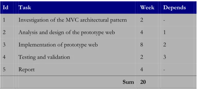
Table 1 lists the tasks to be performed, the time devoted to it and the dependencies between them.
Id Task Week Depends
1 Investigation of the MVC architectural pattern 2 - 2 Analysis and design of the prototype web 4 1 3 Implementation of prototype web 8 2 4 Testing and validation 2 3
5 Report 4 -
Sum 20
Table 3-1. Tasks and temporary planning.
The development of activity 5, Drawing from memory, was carried out in parallel to other project tasks.
The temporary ordination and task dependencies, is graphically illustrated in Figure 2, for the Gantt chart.
3.4 Cost estimate
This section of the chapter we will make an estimate of project costs to develop. This information is very important, and it is an essential step in any engineering project. Used to study the feasibility of the project, and used to the knowledge of the investments required for their development.
Software resources we do not want that involve extra cost neither for developer nor customer, so the analysis will focus on developing search tools freely licensed. We shall discuss the most interesting aspects of the budget, as summarized in Table 2.
The total cost of the laptop is 8000 Kronor. However in the table is 1000 Kronor, because it takes into account the proportionate cost in the 6-month duration of the project, considering that the laptop had a useful life of 48 months.
The total cost wireless mouse is 200 Kronor. However in the table is 50 Kronor, because it takes into account the cost proportional to the 6-month duration of the project, considering that the mouse had a useful life of 24 months.
To calculate the number of hours at different stages of the project, we have relied on the section of the development and planning phases (See 3.3), where an estimated duration of each of the tasks for weeks.
In one week, the worker performed a total of 30 hours of useful work (5 days * 6 hours / day)
The gain corresponds to the margin of profit the company earns the realization of the project; it works not only to cover costs.
Resource Amount Unit cost Total HARDWARE Laptop 0,125 8000 Kr 1000 Kr Wireless mouse 0,25 200 Kr 50 Kr SOFTWARE Tomcat 1 0 Kr 0 Kr JDK 1 0 Kr 0 Kr NetBeans 1 0 Kr 0 Kr
Visual Paradign 8.0 (Community
Version) 1 0 Kr 0 Kr
Office suite 1 0 Kr 0 Kr
SOFTWARE ENGINEERING
Investigation of the MVC and usability 60 hour 500 Kr/h (analyst) 30000 Kr Analysis and design 120 hour 500 Kr/h (analyst) 60000 Kr Implementation of prototype web 240 hour 300 Kr/h (programmer) 72000 Kr Testing and validation 60 hour 300 Kr/h (programmer) 18000 Kr
Report 120 hour 500 Kr/h (analyst) 60000 Kr
OTHER TYPES OF COSTS
Bound and printed memory 3 500 Kr 1500 Kr
Internet 6 month 300 Kr 1800 Kr
Costs 244350 Kr
Benefit (20%) 48870 Kr Subtotal (benefit included) 293220 Kr
VAT (25%) 73305 Kr
TOTAL 366525 Kr
3.5 Users profile
User profiles allow obtaining better understanding of user and definition final goals, which later were transformed in functional requirements of the application. 3.5.1 User profile: student
Overview
Any student, who wants to know another city or to give information of their own city.
Characteristics of the user
Students have a high knowledge in the use of computers. They are accustomed to using similar applications.
The average educational level is high school or college. Read and write without difficulty and have medium or high knowledge of another language (mostly English). The average age does not exceed 23 years.
His experience in using similar applications is high, since over 80% of students manage social networks. His experience with computers is high. Use computers regularly.
Goals
Final goals
Meeting new cultures.
Practicing languages.
Be done to help people unfamiliar with the city.
Make known their city to others.
Meeting people from different places.
Know the city and information about places of interest for leisure, cultural or related to the university.
Keep informed of interesting events that take place in that city.
Do not feel lost in the destination.
Know the culture of the place where you will live.
Do not waste time answering questions from other students.
Sometimes the user does not want to waste time and want to know very quickly what are the most important events that will be done the same day is viewing.
Usability requirements
The indigenous student has no problem when using an application, so they are very critical when evaluating an interface. This application will be used daily and a medium time, so you have to be highly usable and safe for them. The interface has to be direct, simple and flexible, always giving all safe to use.
Keep in mind that the native student cannot afford to waste much time when creating an event, see what messages has, and this should be taken into account especially when designing the interface.
The display shall be part exclusively devoted to tasks that students can do directly, so they do not get lost in navigation. Thus we get that in a few steps to get their purpose.
3.6 Requirements capture
3.6.1 Functional requirements analysis
The functional requirements allow, in a clear and concise way, define the ultimate goals of potential users of the system. With this, we get that from these requirements, we obtain the prototype use cases.
The functional requirements of the prototype software we are developing are:
Register in the application. It consists of what a particular type of user can
register or not.
o A user himself can register in the system. o A user can register an event.
Application management. It consists of what a particular type of user can
manage in the application or not.
o Access the system by identifying. o Create an event.
o Join an event. o Evaluating an event. o Write a private message. o Make friends.
o Edit profile.
o Join one or more cities.
Consultations. Consists in the possibility that consultations can be made and these
are displayed in a simple and direct way to the user.
o Consult the list of friends.
o Consult the list of cities the user joined. o Consult the events user will go.
o Consult the events of the cities that user has joined.
o Consult private messages that others users have written to him. o Consult users.
As we can guess at this point, the application is an architecture client – server. This means that the server will run transactions that one or more clients, simultaneously, request through an electronic device. We will explain the non – functional requirements of these two parts of the architecture.
3.6.2.1 Non – functional requirements. (Server).
Hardware
o Speed: The server must be fast enough to run the application in the shortest possible time and with greater reliability.
o Memory: The server must dispose have sufficient RAM to do the operations the application and data base request.
o Storage. The server must have sufficient a storage capacity to store the data base which works the application and allow the transactions between the two applications.
Software
o The server must have installed a manager of data base (DBMS). Our application has been tested and designed with the DBMS of MySQL in a version that allow cipher keys. (MySQL version 4.0 or higher).
o The server must have installed JDK 1.6 or higher for exist compatibility with the used libraries.
o The server must have installed Apache Tomcat with a compatible version to JDK installed. All serve through Tomcat, because the application only uses JSP and Servlets.
3.6.2.2 Non – functional requirements. (Client)
Hardware
o Speed: The PC should be fast enough to run a web browser with JavaScript enabled. Today this is no problem, as any personal computer microprocessor is capable of fulfilling this task.
Software
o It should have of a compatible browser with JavaScript. o JavaScript should be enabled.
3.7 Task analysis: Use cases
3.7.1 Introduction to use cases
A use case represents a situation or a interaction task of one or more user with application. Use cases are tasks meaningful, consistent and relatively independent that actors to perform in their daily work.
Unique name.
Use case diagram.
Actors involved.
Inlet conditions.
Flow events.
Output conditions.
Exceptions.
In our system we have an actor (previously described in user profiles): student. Now is the time to create the different use cases. When performing this action is important that each of the functional requirements already defined, appears in at least one use case, as we have stated previously.
We emphasize that there can be new use cases, which does not appear any of the requirements, because we are in a phase of refinement of the system.
3.7.2 Boundary diagram
A step towards the creation and description of the different use cases is to obtain a diagram that fully describes the system functionality. This is called boundary diagram.
The use cases shown in a boundary diagram can be sufficiently accurate or conversely can be concretized in greater detail. When a use case is detailed you can use two kinds of relations:
<< extend >>: is a relationship that represents exceptional behaviour of the use case.
<< include >>: is a relationship that represents the need for another use case.
Below are descriptions of the use cases and diagrams associated with each of a more precisely:
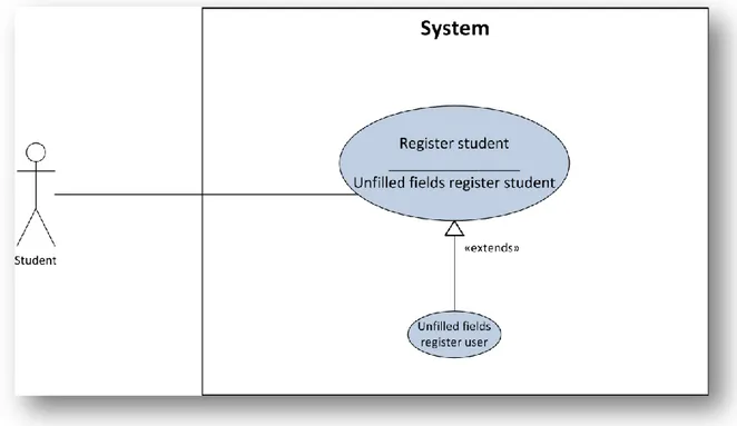
3.7.3 Use case: Register student
Figure 3-5. Use Case: Register Student.
Actors involved: student. Inlet conditions: -
Flow events:
1. Student fills mandatorily the following attributes: name, email, password, sex and birthday.
The system notifies the user and returns to step 1. 3.7.4 Use case: Identification student
Figure 3-6. Use Case: Identification Student
Actors involved: student. Inlet conditions:
Student has been registered correctly.
Flow events:
1. Student enters her/his credentials: e-mail and password. 2. The system successfully authenticates the student.
Exit conditions:
Student accesses the system.
Exceptions:
1a. Student does not fill correctly the data and presses Sign in.
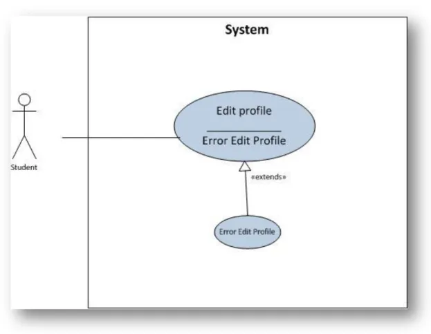
3.7.5 Use case: Edit profile
Figure 3-7. Use Case: Edit Profile.
Actors involved: student. Inlet conditions:
Student has been identified correctly.
Flow events:
1. Student fills information that he/she wants updates. 2. The system successfully registers new profile of the user.
Exit conditions:
Student has a new profile.
Exceptions:
3a. Student does not fill correctly the data and presses Save.
3.7.6 Use case: Create event
Figure 3-8. Use Case: Create Event
Actors involved: student. Inlet conditions:
Student has been identified correctly.
Flow events:
1. Student accesses the option Create Event.
2. System displays a screen which user establishes the place, time and a description of event.
3. Student fills all attributes and press Save. 4. System registers the event.
Exit conditions:
System stores new event.
Exceptions:
3a. Student cancels the operation.
System does not register new event and return City. 3b. Student does not fill correctly the data and presses Save.
3.7.7 Use case: Consult friends
Figure 3-9. Use Case: Consult friends
Actors involved: student. Inlet conditions:
Student has been identified correctly.
Flow events:
1. Student accesses option my friends.
2. System displays a list with friends of the student.
Exit conditions: - Exceptions: -
3.7.8 Use case: Send a message
Figure 3-10. Use Case: Send a message
Actors involved: student. Inlet conditions:
Student has been identified correctly.
Flow events:
1. Student access a friend and presses send a message.
2. System displays a screen which user setting the message text. 3. Student writes the message and presses send.
4. System sends the message to the right person.
Exit conditions:
System stores the new message.
Exceptions:
3a. Student cancels the operation.
System does not register new message and return Friend. 3b. Student does not fill correctly the data and presses Send.
The system notifies the user and returns to step 2. 3.7.9 Use case: Read a Message
Figure 3-11. Use Case: Read a Message
Actors involved: student. Inlet conditions:
Student has been identified correctly.
Flow events:
1. Student accesses the option: Messages
2. System displays a list of messages, and specially marks unread messages. 3. Student chooses the message.
4. System displays the complete message.
Exit conditions: - Exceptions: -
3.7.10 Use case: Search
Figure 3-12. Use Case: Search.
Actors involved: student. Inlet conditions:
Student has been identified correctly.
Flow events:
1. Student writes a text in search box. 2. System displays a results list.
Exit conditions: - Exceptions: -
3.7.11 Use case: Confirm Friend Request
Figure 3-13. Use Case: Confirm Friend Request
Actors involved: student. Inlet conditions:
Student has been identified correctly.
The user has pending friend requests.
Flow events:
1. Student accesses the option Friends.
2. System displays a list with the pending friend requests. 3. Student presses Accept in one of them.
4. System registers a new friend on the user’s profile.
Exit conditions:
System registers the new friendship in the system.
Exceptions: -
3.7.12 Use case: Cancel Friend Request
Figure 3-14. Use Case: Cancel Friend Request
Actors involved: student. Inlet conditions:
Student has been identified correctly.
The user has pending friend requests.
Flow events:
1. Student accesses the option Friends.
Exceptions: -
3.7.13 Use case: Add friend
Figure 3-15. Use Case: Add Friend
Actors involved: student. Inlet conditions:
Student has been identified correctly.
Student has done a search in the system.
Flow events:
1. Student chooses a person of the list and presses Add friend. 2. System notifies the appropriate person the friend request.
Exit conditions:
System registers the friend request in the system.
3.7.14 Use case: Join city
Figure 3-16. Use Case: Join City
Actors involved: student. Inlet conditions:
Student has been identified correctly.
Student has done a search in the system.
Flow events:
1. Student chooses a city of the list and presses Join.
2. System displays in the list of cities of the user the new city.
Exit conditions:
System registers the city in the user profile.
3.7.15 Use case: Evaluate Event
Figure 3-17. Use Case: Evaluate Event.
Actors involved: student. Inlet conditions:
Student has been identified correctly.
Student has event in her/his profile.
Flow events:
1. Student accesses the option Events and presses Like or Dislike in an event. 2. System increase in one Like or Dislike.
Exit conditions:
System registers the assessment of user.
Exceptions: -
3.7.16 Use case: Consult Events
Actors involved: student. Inlet conditions:
Student has been identified correctly.
Flow events:
1. Student chooses the option Events
2. System displays a list of events of the cities that user is joined.
Exit conditions: - Exceptions: -
3.7.17 Use case: Join Event
Figure 3-19. Use Case: Join Event.
Actors involved: student. Inlet conditions:
Student has been identified correctly.
Flow events:
1. Student chooses the option Events
2. System displays a list of events of the cities that user is joined. 3. Student chooses one of them and presses Join.
4. System stores this event to the list of events that user will go.
3.7.18 Use case: Disjoin Event
Figure 3-20. Use Case: Disjoin Event.
Actors involved: student. Inlet conditions:
Student has been identified correctly.
Student is joined at least one event.
Flow events:
1. Student chooses the option My Events.
2. System displays a list of the events that the user will go. 3. Student chooses one event and presses Disjoin Event. 4. System deletes the event of the list of the user.
Exit conditions:
System registers this action in the system.
3.8 Task analysis: HTA diagram
Analysis task is defined as:
The process of analyze how a user realizes his/her work. Furthermore, know the things they do, and things on which they act, information that they need to carry out, and goals that leads them to do this work.
The purpose of a user is not interacting with computer, but comply some goals. The interaction is the means by which that goal is met. Thus, knowledge of the user's task requires knowledge of their goals and motivations; we know this, for example, through the whole process of analysis we carry so far.
Task analysis is done at two levels. At one level the structure of each individual
interaction task is determined, and a second level determines the architecture of all tasks of interaction as a whole.
The first level has already been covered with the use cases, where we know the dialogue between actor and system, i.e. the structure of the task. The second level is usually expressed as a diagram with the HTA.
HTA diagram expresses the information in a visual format easier to understand
for a development team. Each task or subtask is represented by a rectangular box and is labeled with its job number in the upper left corner, followed by the name of the task in the next line.
The task hierarchy is represented by a horizontal line at the top of the boxes, while simple tasks or activities (i.e., those which are not subdivided) are represented by a horizontal line at the bottom of the box represents them.
Plan 0:
Do 1 and 2. Do 3, 4 and 5 in any order until complete.
Plan 2:
Do 2.1, if credentials are incorrect return 2.1
Plan 3:
Do 3.1, if attributes are incorrect return 3.1
Plan 4:
Do 4.1, 4.2, 4.3, 4.4 and 4.5 in any order
Plan 4.2:
o Do 4.2.1, 4.2.2 and 4.2.3 in any order
Plan 4.3:
o Do 4.3.1, 4.3.2 and 4.3.3 in any order
Plan 4.4:
o Do 4.4.1, 4.1.2 and 4.4.3 in any order
Plan 4.5:
o Do 4.5.1, 4.5.2 and 4.5.3 in any order
Plan 4.5.1:
Do 4.5.1.1 and 4.5.1.2 in any order
Plan 4.5.2:
Do 4.5.2.1, 4.5.2.2 and 4.5.2.3 in any order
We can see that is perfectly expressed the architecture of the interaction tasks of the student role. We observe how tasks are connected to each other through the hierarchy.
The plans describe in what order and under what conditions subtasks are performed. It is a very important task because from these we can determine much of the navigation paths in our application.
3.9 Design of the system interface
Once the analysis phase, the next phase of software engineering is the design. With the design seeks to obtain the class diagram of the prototype, which translates to a programming language allowing the deployment of the prototype web usable.
Before obtaining the class diagram should make the screen design and navigation between them (storyboards). Then there will be a most laborious task throughout this project: get the class diagram from the screen design. Later specify how, and what matters now is the next step: designing the system interface, consisting of design screens and storyboards.
3.9.1 Screens design
To perform the preliminary design of the user interface is possible to use different tools, one of which prototyping screens, either freehand drawings, cutting and pasting pieces of paper which represent components, or by using digital media. In my case, screen design will integrate with digital media, using Photoshop.
3.9.1.1 Login Screen
If the user is not registered, they are asked to fill in the second form. If it is registered user he/she have to fill in the fist form.
3.9.1.2 Home Screen
Figure 3-23. Home screen.
The appearance of the Web application in most cases is the same. Above we can see a navigation bar at the top of the page. Here we can find a link that leads to principal page of user, a text box which we can search both, people and cities, profile access and log out.
The left navigation bar, you can see the profile picture and the name of the user, and there is a series of navigation options. In the middle we have the dynamic changes of the web that changes throughout the user navigation.
3.9.1.3 Edit Profile Screen
Figure 3-24. Edit profile screen.
Student accesses to this page when has pressed profile on the navigation bar at the top right.
Here, user has the option to change his/her name, email, password, birthday or city. In addition, the user can change her/his profile picture.
3.9.1.4 Inbox Screen
Figure 3-25. Inbox screen.
The user can view a list of all his/her messages sorted by user pressing the Inbox option on left navigation bar.
3.9.1.5 Details Message Screen
Figure 3-26. Details message screen.
User can view the detail of message, and this is the thread of conversation he/she has with other user. Furthermore, user can send another message from this screen.
3.9.1.6 My Events Screen
Figure 3-27. My events screen.
The user can view a list of all his/her events pressing the Inbox option on left navigation bar. Furthermore user can vote these events or changes her/his mind and not go to the event, thus will be removed from this list.
3.9.1.7 Detail Event Screen
Figure 3-28. Detail Event Screen.
Here, user can view details of an event, and if it is interesting she/he can join the event or vote it.
3.9.1.8 My cities Screen
Figure 3-29. My cities screen.
The user can view her/his cities, with the option to remove it from the list or to access events clicking the name of the city.
3.9.1.9 Add Event Screen
Figure 3-30. Add event screen.
User can add an event to the city which he/she is browsing. User must fill in the details shown on the screen and this event will appear in the list of events.
3.9.1.10 City Screen
Figure 3-31. City screen.
Here, user can view the events of a particular city. And he/she can join event or vote event.
3.9.1.11 Search Screen
Figure 3-32. Search screen.
3.9.1.12 My friends Screen
Figure 3-33. My Friends Screen.
3.9.1.13 Details Friend Screen
Figure 3-34. Detail friend screen.
3.10
Classes diagram
3.10.1 Classes diagram
Class diagrams are used to show the static structure of the modeled system. Class diagrams can consist of classes, interfaces, packages, relations and even instances as objects or links.
Is a powerful design tool, it is a powerful design tool that helps developers to plan and establish the structure of the system before writing any code.
Class diagrams have the follow components:
Classes: These are the fundamental components of class diagrams. Its general notation is a rectangle divided into three sections: The first is the name of the class, the following attributes and the last operations.
Relations: a semantic connection between elements. There are four main types of relations:
o Generalization is a relation of specialization.
o Association: a structural relationship. It reflects a relationship between two independent classes that remains during the life of objects or at least for a time. There are two types: aggregation and composition.
o Implementation: is a contractual relationship in which a class specifies a contract that another class guarantees that will comply. o Dependence: is a relationship of use, namely the implementation of
a class depends on another.
As we know, the design scheme that will be used shall be a Model-View-Controller (MVC). Undoubtedly, and as we pointed earlier, the most important message provided by this design scheme is to keep the model as independent as possible of the view and controller, so you can change either without modification in other components.
Model Package: Implements the application logic, i.e. it stores all data,
the status of the application and has the methods that manipulate these data.
Controller Package: controller layer will perform all the control of the
system and allow the user to perform any operations on it. This package constantly will use classes of Model package to obtain and save information, and will be responsible for operating with the data for display in the view.
View Package: Displays a usable interface to the user, containing the data
4 Findings and analysis
4.1 Introduction
The ultimate goal of software development process, followed by the previous points as analysis and design, is to get a functional system, for which we must proceed to a concrete implementation of it, translating class diagrams and interaction in code that can be executed on a computer.
It makes no sense to explain the implementation carried out, nor is it appropriate to describe the source code since this is a simple translation of the class design made. As indicated in the following paragraphs are implementation decisions and the evaluation tests of the prototype itself.
4.2 Implementation decisions
Encode the prototype has been relatively easy because most of the process is based on translating the class diagram obtained in Chapter 3. However, there have been situations in which it has been necessary to take concrete decisions to achieve the purpose of implementing the prototype of the best. Among the implementation decisions taken include the following:
Using a database that allows encrypted passwords for users of the system. Use support information-sharing sessions between Servlet and JSP system, checking that there are no illegal accesses to it: The Java support sessions to
share information without using the GET and POST methods. That is, we can add any attribute to the session, without having to send it through the methods described above, and consult at any time. Not only is this the advantage of using sessions, perhaps the most important is the ease with which it can detect illegal access to the application. If for example in our application a user logs on, only have access to JSP and Servlet files allowed by the system for that type of user, if you try to access a JSP file that is not part of your session, the system detected quickly and throws an exception that prevents access to the system that way.
Handle exceptions common to have a processing different from the rest:
There are accesses to the database exceptions occur because the data requested does not exist. We have created a class for each of the exceptions that can be controlled, so that if it occurs at some point, we are notified via the message specified in the operation toString () for each one of them.
I created a class to access the database for each of the existing tables: JPA
creates tables in the database automatically, and as we described above, adding, modifying or deleting items from a table is made from Java operations independent of the database being used. But all these operations should be
We used a library of the editorial "O 'Reilly" to upload files (images, etc...) through a form [10]: We used a library of the editorial "O 'Reilly" to upload files
(images, etc...) Through a form [12]: This study uses a library that allows you to upload to the server in a comfortable manner and in a few lines code, files that are in the user's hard drive. For example, to upload profile photos.
I used the JAVA files: "properties" for if in the future I want to add a new language to the application, it is easy.
Table 4-1. File Properties of JAVA
4.3 Validation of the project
4.3.1 Black box testing
This type of testing is performed on the software interface and seeks to demonstrate that: [11]
Software functions are operational.
That input is properly accepted.
Output is correctly produced.
The integrity of external information is maintained. Black-box testing uncovers errors of the following categories:
In-correct or missing functions.
Errors in the data structures or external data base access.
Performance errors.
Initialisation and termination errors.
The type of black-box testing will be conducted in this project will be equivalence partitioning method (That is to use a small subset of all possible inputs to find the highest likelihood of errors).
Thus, as a black box testing is based on the software interface for each Web page can contain any problems with the values supplied by the user, will make black-box testing. All those pages that do not need to supply values shall be exempt from testing because there is no possibility of interface errors.
The components of the view and their respective black-box testing are exposed as follows:
4.3.1.1 Site “Access”
Test plan
Inlet conditions Valid classes Invalid classes
$Unregistered user 1. False 2. True $key = $password 3. True 4. False
Table 4-2. Test plan of Access
Valid classes (Correct identification is expected):
Registered user (1).
$key = ‘hello’ and $password = ‘hello’ (3).
Invalid classes (It is expected an error message):
Unregistered user (2).
$key = ‘hello’ and $password = ‘bye’ (4).
4.3.1.2 Site “Registration”
Test plan
Inlet conditions Valid classes Invalid classes
$email1 = $email2 9. True 10. False
Table 4-3. Test plan of Registration
Valid classes (Correct identification is expect):
$full_name = ‘Iván Pérez’ (1).
$email = ‘example@gmail.com’ (3).
$repeat_email = ‘example@gmail.com’ (5).
$password = ‘hello’ (7)
$email1 = ‘example@gmail.com’ and $email2 = ‘example@gmail.com’ (9).
Invalid classes (It is expected an error message):
$full_name = ‘’ (2).
$email = ‘’ (4).
$repeat_email = ‘’ (6).
$password = ‘’ (8).
$email1 = ‘example@gmail.com’ and $email2 = ‘hello@gmail.com’ (10).
4.3.1.3 Site “Edit profile”
Test plan
Inlet conditions Valid classes Invalid classes
Size($picture_profile) <
100 KBs 1. True 2. False
Extension($picture_profile)
= ‘jpg’ 3. True 4. False
$full_name 5. Not empty string 6. Empty string $email1 = $email2 7. True 8. False
$old_key = $old_password 9. True 10. False $new_key1 = $new_key2 11. True 12. False
Table 4-4. Test plan of Edit profile
Valid classes (Correct identification is expect):
$picture_profile = ‘picture_low_resolution.jpg’ (1, 3).
$old_key = ‘hello’ and $old_password = ‘hello’ (9).
$new_key2 = ‘bye’ and $new_key2 = ‘bye’ (11).
Invalid classes (It is expected an error message):
$picture_profile = ‘picture_high_resolution.jpg’ (2).
$picture_profile = ‘picture_low_resolution.odt’ (4).
$full_name = ‘’ (6).
$email1 = ‘example@gmail.com’ and $email2 = ‘hello@gmail.com’ (8).
$old_key = ‘hello’ and $old_password = ‘bye’ (10).
5 Discussion and conclusions
5.1 Discussion of findings
These are the results from the project:
A web prototype has been created and in this prototype works the functional requirements which were established in the analysis phase.
Most usability principles have been taken into account when creating the site prototype.
The project has been carried out following with precision the planning and performing the steps in the software engineering: analysis, design, implementation and testing.
A report has been done which defines the whole process which has been carried out in the project.
Improvements have been identified in the project, which have emerged over the realization of the same.
5.2 Conclusions
We must highlight the importance of implementing a prototype like this, because it allows students to do so is not difficult to adapt to a new city.
But the work could be further continued because every application is susceptible of being enhanced and much more if it is a prototype. As indicated below some extensions:
Upload the application to a server, and publish the application.
Creating an interface for mobile devices, at least for the more important actions of system.
Creation of a system to recover passwords.
Adding a new role to the system: Administrator.
Using AJAX for dynamic queries is faster.
Ability to notice of notifications via email.
Addition of a new module for the user to ask questions about a city.
Identify any user-centric improvements and implement them, always trying to bring that part to the future achievement of a final system.
On a personal basis I have to emphasize that the realization of this project has helped me to implement many of the methodologies and skills acquired during my years of education, and others I have had to acquire during their development. The most positive thing is I get improvement in my ability to create user – centered designs. I think it is very good for an engineer, and always try to get this in the future.
Finally, I would like to turn this into a real project, because I think it is a not covered need in the society.
6 References
[1] ISO 9241 – 11: 1998. Ergonomic requirements for office work with visual display terminals (VDTs): Guidance on usability.
http://www.iso.org/iso/catalogue_detail.htm?csnumber=16883 (ACC. 13 February 2012).
[2] Oracle. JavaServer Pages (2010)
http://java.sun.com/products/jsp/overview.html (ACC. 13 February 2012).
[3] Ian Pouncey, Richard York. (2011) Beginning CSS: Cascading Style Sheets for
Web Design. 3th edition. ISBN: 04-70-89152-1.
[4] ORACLE: The Java Persistence API.
http://www.oracle.com/technetwork/articles/javaee/jpa-137156.html
(ACC. 15 February 2012). [5] Oracle (base de datos)
[6] Reenskaug, T. “The original MVC reports” Dept. Informatics University of Oslo (1979). http://heim.ifi.uio.no/~trygver/2007/MVC_Originals.pdf
(ACC. 17 February 2012).
[7] Netbeans (2012). http://netbeans.org/community/releases/70/ (ACC. 17 February 2012).
[8] Erasmoos (2010). http://en.erasmoos.com/ (ACC. 25 Februay 2012). [9] Facebook (2012). http://www.facebook.com/help/events (ACC. 1 March
2012).
[10] O’ Reilly (2005) http://www.servlets.com/cos/ (ACC. 26 April 2012). [11] Roger S. Pressman, Ph.D. (2001) Software Engineering. A Practitioner’s approach.