VTI meddelande
No. 778A - 1996
A new flexible pavement design method
Formulation of a user-friendly mechanistic/empirical design system for Swedish conditions
Lennart Djarf, Leif G. Wiman and Hakan Carlsson
Swedish Road and
VTI meddelande
No. 778A - 1996
A new flexible pavement design method
Formulation of a user-friendly
design system for Swedish conditions
Lennart Djarf, Leif G. Wiman and Hakan Carlsson
Swedish National Road and U Transport Research Institute Cover: C. Tonstrom, VTI
Publisher: Publication:
Meddelande 778A
Published: Project code:
Swedish National Road and 1996 60058
/ Transport Research Institute
S-581 95 Linkoping Sweden Project:
New flexible pavement design method Printed in English 1997
Author: Sponsor:
Lennart Djiarf, Leif G Wiman and Hakan Carlsson The Swedish National Road Administration
Title:
NEW FLEXIBLE PAVEMENT DESIGN METHOD. Formulation of a user-friendly mechanis-tic/empirical design system for Swedish conditions.
Abstract
Pavement design means selecting materials and determining layer thicknesses so that the road fulfils the performance requirements for a chosen period.
Mechanistic design methods make it possible to adapt designs to the particular conditions. The need for a flexible design system is motivated by the development of vehicles and especially tyres (increased inflation pressure and wide base tyres). In recent years, development has taken a direction that is un-favourable in regard to road wear.
An expected increase in usage of secondary and recycled road materials in the future is a further motive for a flexible design system.
Work on developing a flexible design system for Swedish conditions has been commissioned by the Swedish National Road Administration and was carried out during the period 1987-1994. The result is described in this report.
The aim of the project was to develop a user-friendly and flexible design system for road pavements which is suitable for Swedish conditions.
The following three principle sections are required for the calculation of the bearing capacity of road pavements based on a mechanistic approach:
e A calculation method for the determination of stresses and strains in the road structure.
e Knowledge of the mechanical properties of the road building materials and of the subgrade, primarily stiffnesses or resilient moduli.
e Design criteria or design values for the stresses and strains that are critical for the bearing capacity of the road structure.
This project has focused on the latter two sections. Calculation of stresses and strains uses an existing computer programme based on linear elasticity theory (Chevron). To make the design system as user-friendly as possible, it was decided to develop it for use in a PC and Windows environment.
In addition to bearing capacity design, an analytical method of design with regard to frost heave based on calculation model developed at an earlier stage is also included in the system.
Finally, the system also makes it possible to calculate the cost of a calculated structure by giving the price per unit for the various pavement materials.
ISSN: Language: No. of pages:
Foreword
This report describes and summarises the work performed in developing a flexible design system for road pavements adapted to Swedish conditions. The work was begun during the second half of the 1980s and was completed as part of the project "A new flexible pavement design method" (1990-1994). The client was the Swedish National Road Administration and the work was conducted in a number of subprojects occupying a large number of researches.
Warm thanks are expressed to all those who have taken part, in particular our principal contact person at the Swedish National Road Administration, Hans Edy Martensson, who played an active role in development and made a great contribu-tion to the design of the user-friendly computer programme.
The report was translated by Tony Palm, Professional English AB.
Linkoping, March 1997
Leif G Wiman
Innehallsforteckning
Summary
1 Short history
2. User requirements
3 Input parameters in earlier design instructions (BYA-84)
4 Stiffness (E-modulus) of subgrade soils 4.1 Background
4.2 Database of subgrade soil moduli 4.3 Discussion of variations
4.4 Table of soil type moduli
5 Design traffic load with regard to cross-distribution
6 Load equivalents
7 Design criteria 7.1 Asphalt strain criterion 7.2 Subgrade criterion
8 Input data
8.1 Heavy traffic
8.2 Type of subgrade soil, drainage conditions and groundwater level!
8.3 Freezing index 8.4 Road type
8.5 Road width, inner verge and costs
9 Material moduli, seasonal classification and bituminous layer temperatures
9.1 Unbound materials 9.2 Bitumen-bound material 9.3 Seasonal classification
10 Calculationprogramme
10.1 Design of GBO and BBO (Gravel/bitumen and crushed rock/bitumen pavements)
10.2 Design with the user's own input 10.3 Frost heave design
VTI meddelande 778A
Sida 15 16 17 18 18 20 24 26 28 29 32 32 34 35 35 36 37 38 38 39 39 39 40 41 41 42 43
11 Further work 45
12 References 46
Appendixes:
Appendix 1: VagDim 95. User's Guide
Appendix 2: Calculation examples using ViagDim 95
A new flexible pavement design method.
Formulation of a user-friendly mechanistic/empirical design system for Swedish conditions.
by Lennart Djirf, Leif G Wiman and Hakan Carlsson Swedish National Road and Transport Research Institute S-581 95 Linkoping
Summary Background
An efficient infrastructure is essential for positive social development. The expan-sion of the road network is an important part of the infrastructure and roads must offer comfortable and safe transport of people and goods. The road engineer's duty is to design roads that have good durability, evenness and friction. The life of a road and the time before damage occurs in the road surface largely depend on the quality of the subgrade, but perhaps even more on the quality of the design of the pavement. Pavement design means selecting materials and determining layer thicknesses so that the road fulfils the performance requirements for a chosen period.
Mechanistic design methods make it possible to adapt designs to the particular conditions. The approach in mechanistic design of a pavement is generally the same as in design of other types of engineering structures. This means that a com-parison between calculated and permitted stresses and strains in the road structure forms the basis for the design. A mechanistic design method will thereby become flexible and adaptable to the particular conditions.
The need for a flexible design system is motivated by the development of vehicles and especially tyres (increased inflation pressure and wide base tyres). In recent years, development has taken a direction that is unfavourable in regard to road wear.
An expected increase in usage of secondary and recycled road materials in the future is a further motive for a flexible design system.
Work on developing a flexible design system for Swedish conditions has been carried on during the period 1987-1994. The results of the work, which has been commissioned by the Swedish National Road Administration (SNRA) are de-scribed in this report.
Aim
The aim of the project "New flexible pavement design method" was to develop a user-friendly and flexible design system for road pavements which is suitable for Swedish conditions.
Method
The following three principle sections are required for calculation of the bearing capacity of road pavements based on a mechanistic approach:
e A calculation method for the determination of stresses and strains in the road structure.
e Knowledge of the mechanical properties of the road building materials and of the subgrade, primarily stiffnesses or resilient moduli.
e Design criteria or design values for the stresses and strains that are critical for the bearing capacity of the road structure.
This project has focused on the latter two sections. Calculation of stresses and strains uses an existing computer programme based on linear elasticity theory (Chevron). To make the design system as user-friendly as possible, it was decided to develop it for use in a PC and Windows environment. During the course of the project, development has been carried on in a number of subprojects as follows:
e SANREMO. New design of road pavement in BYA (earlier Swedish Natio-nal Road Administrations specifications) in the short term,
e evaluation of FWD measurements with regard to the E-moduli of various types of subgrade soil,
e design traffic load (lateral distribution), e load equivalents.
e criterion for strains in bituminous layers based on field studies, e statistical design/risk assessment
e formulation of mechanistic/empirical design system.
SANREMO. New design of road pavements in BYA in the short term.
SANREMO is a Swedish abbreviation for "purging, renovation and modification" of the design chapter in the SNRA's road construction directives, BYA 84. The project was originally started by the SNRA but was transferred to VTI (Swedish National Road and Transport Research Institute) in 1990. The aim of the project was to produce, within a relatively short period, a mechanistic design method based on the method used at that time in BYA 84. In this way, it would be possible to create a theoretical basis for the design directives in BYA without any special research and development work, and thereby achieve a more flexible design method for meeting rapid changes in road construction and traffic growth.
The results of the SANREMO project are a description of a mechanistic proce-dure for bearing capacity design of road pavements. With the assumptions and adaptations that were made, reasonable agreement was obtained with the pave-ment designs in BYA 84 which were considered to agree best with reality. The complete report on the SANREMO project is given in VTI Notat V 187.
Some of the results of the SANREMO project have been used in the develop-ment of the new design system.
Evaluation of FWD measurements with regard to the E-moduli of various types of subgrade soil.
As mentioned in the introduction, the qualities of the subgrade are of great import-ance for the changes in the condition of a road with time and traffic. Mechanistic design of road pavements requires knowledge of the stiffnesses or E-moduli of various types of subgrade soil. Determination of the E-moduli values for fine-grained soil types can be performed on a laboratory scale, while testing of graded soil types (moraines) is more difficult to perform in a laboratory environment.
grained soil types can be performed on a laboratory scale, while testing of graded soil types (moraines) is more difficult to perform in a laboratory environment.
The aim of this sub-project has been to determine relevant (realistic) E-moduli values for various types of subgrade soil based on FWD measurements on existing roads with known subgrade.
A large number of measurements obtained in different years and seasons have been evaluated. The E-moduli values obtained have been systematised and arranged in soil type groups. Design E-moduli values have been determined for different seasons and drainage conditions. These values have been entered together with soil type designations in a material database, thereby forming a basis for the design calculations.
Design traffic load
In mechanistic design, calculations are made of critical stresses and strains in the road structure from a wheel load on the road surface. As a rule, stresses and strains are greatest directly beneath the load and decrease with distance from the load. To take into account the fact that the actual traffic on the road does not load the road structure in the same position laterally, the sub-project has clarified the lateral distribution of heavy vehicles on different types of road. The importance of different lateral distributions with regard to critical strains has been studied and determined for tensile strain in the asphalt layers. The lateral distribution of heavy vehicles depends on a number of factors, of which the most decisive over a longer time perspective is the cross-section of the road. Correction factors have been calculated for different types of road. These have been used in estimating traffic when developing the asphalt strain criterion, see below, and are also used in the design system for calculating cumulative traffic load during the design period.
Load equivalents
Extensive work has earlier been done to describe as correctly as possible the in-fluence of traffic load on road deterioration. The damaging effect depends on a large number of factors, of which the most important are axle load, tyre type, in-flation pressure, and wheel and axle configuration.
Most work is of the nature of "theoretical calculations". As a rule, these are to no small extent dependent on the input data used in the calculations. For this reason, full-scale measurements of tensile strain in (asphalt) pavements reported in the literature have been used as the basis for a general model for estimating load equivalents for a given pavement thickness. Models have been produced for two pavement thicknesses. The independent parameters are axle load, tyre type (width), inflation pressure and wheel configuration. In regard to axle configurations, the result of strain measurements is dependent on the evaluation method. The results of the AASHO experiments are therefore being used until further notice as a basis for estimating the load from tandem axles, while triple axles are treated as single axles in the system.
Criterion for strains in bituminous layers based on field studies
As mentioned above, one of the fundamental requirements in mechanistic design of pavements concerns design criteria for critical strains in the road structure.
Tensile strain at the bottom of the asphalt layer is generally regarded as critical with regard to the risk of fatigue cracking.
A large number of tensile strain criteria have been developed around the world, most being based on laboratory experiments. It was considered difficult to select one of these since Swedish bitumen bound roadbases are lean (low binder content) by international comparison and have a soft binder (B 180). In view of this, it was decided to develop a "Swedish" asphalt strain criterion applicable to Swedish mixes and climatic conditions and based on our own field studies.
These studies comprised a follow-up of 3-6 km long sections of 12 newly built roads. These have been followed up by means of FWD measurements, vechicle classification counts, measurements of unevenness and rut depth, and yearly manual damage surveys.
The aim was to determine the relation between tensile strain at the bottom of the asphalt layer and the number of equivalent 100 kN:s single axle load that the road can withstand before the first crack appears in the asphalt layer.
The tensile strain was calculated from FWD deflection measurements and a regression relation based on theoretical calculations of deflections and tensile strain at the bottom of the asphalt layer.
The vehicle classification counts have been used in combination with axle load measurements on corresponding types of roads as a basis for estimating the traffic load.
Drill cores have been taken from ten road sections and used in the laboratory to determine the temperature dependence of the fatigue properties. The tests were performed at temperatures of +4, +10 and +15°C. The criterion obtained in the field represents +10°C. The laboratory curve for +10°C gave a life of about 10 % of the field curve, and the laboratory curves have therefore been shifted parallel to match the field curve (shift factor = 10).
In small strains, poor adaptation to the field observations is obtained, with a conventional strain criterion (a straight line with logarithmic scales). For this reason, a "correction" factor has been integrated in the criterion, which gives a bent curve with logarithmic scales.
Statistical design/risk assessment
Like all other types of structural design, pavement design involves uncertainty. In recent years, this aspect has attracted increasing attention among engineers. However, the problem is somewhat difficult to deal with, partly because the uncertainty in the finished construction is not constant in time (probable life is in practice a statistical distribution), but is partly dependent on the development of production techniques, quality assurance work, etc.
In order to take into account the uncertainty in design, the known dispersion in the asphalt strain criterion obtained will be used and entered in connection with validation of the design system. The certainty which is thereby chosen will be made dependent on road type (national, regional, local).
Formulation the design system
The formulation of the design system has been carried out jointly by the VTI, the National Road Administration and an EDP consultant. The principal goal has been maximum user-friendliness and flexibility of the system. The design system has
gramme itself. Both parts have been designed in Windows environment for use on a PC.
The material database contains information (E-moduli and Poisson's ratio) on the mechanical properties of various pavement and subgrade materials. For bitu-men-bound materials, the E-modulus is specified as a function of temperature, for unbound pavement materials constant E-moduli (independent of season) are used and for subgrade materials the E-moduli are a function of season and ground water level in combination with cutting or embankment. For bitumen-bound base courses (AG) and for subgrade materials, the design criteria are specified. As men-tioned earlier, the AG criterion is obtained through field studies, while the sub-grade criterion is the same as that used in SANREMO. Other information, such as density, water ratio and heat conductivity, is given as a basis for design with regard to frost heave.
The E-moduli entered in the first version of the material database have been produced both within the SANREMO project, with minor modifications, and in the project described earlier "Evaluation of FWD measurements with regard to the E-moduli of various types of subgrade soil".
The material database can easily be expanded with new material, provided that the required material properties are known (e.g. E-modulus, design criteria etc.).
The other part of the system, the calculation programme itself, consists of a number of parts (windows) for entering input parameters to the design calcula-tions. The three parts preceding the design part itself are named Object Identifica-tion, Traffic Description and Sectioning.
Object Identification entails giving the object a name, indicating the particular climatic zone expressed in cumulative cold and choosing a design period, e.g. 20 years. Road category (national, regional or local) and cross section, e.g. a 9-metre road, are also stated. Finally, it is possible to state current prices of the pavement material to be used, which gives a calculated cost for the pavement structure resul-ting from the design.
The next part, the Traffic Description, concerns a description of the heavy vehicles. Here, basic data must be entered for calculating the total number of standard axles (100 kN) per lane during the design life. If nothing is known about the heavy vehicles, use is made of the AADT for total traffic combined with a choice of mixed or extremely heavy vehicles. Together with a specified calculated annual growth (in %), the total number of standard axles is calculated and later used as a basis for design.
The third part, Sectioning, makes it possible to divide the object into sub-sections for adaptation to changing conditions. Soil type in the subgrade, drainage conditions and ground water level (if known) are stated for each subsection. Finally, the slope of the inner verge is stated, which is used together with the road's cross section in volume calculation as a basis for costing.
Pavement design
After entering the above information, the design work itself remains. Here, three different pavement types can be chosen, i.e. two standard types, GBO (gravel/bitu-men pave(gravel/bitu-ment) and BBO (crushed rock/bitu(gravel/bitu-men pave(gravel/bitu-ment), according to VAG 94 (the latest National Road Administrations specifications), in addition to an arbitrary choice. If the standard types according to VAG 94 are chosen, the thickness of the wearing course, unbound base course and upper sub-base are
thickness of the wearing course, unbound base course and upper sub-base are predetermined. The programme calculates the necessary thickness of the bound base course (AG) and lower sub-base (protective layer) if used. If the user's own pavement type is chosen, the number of layers can be specified (up to nine). In general, the programme can design every layer, although this requires design conditions/criteria to have been entered in the material database for every material chosen for the various layers.
Regardless of which pavement type is chosen, the cost for each layer is calculated and summated to a total cost for the pavement.
In addition to bearing capacity design as above, design with regard to frost heave based on the requirements set out in VAG 94 is included.
1 Short history
About ten years ago, an outspoken article published in the Transportation Research Board's (TRB) series of reports stated that the USA "had been asleep" regarding the trend in a factor important for the future of the road network, namely changes in the tyre pressures of heavy vehicles. The statement should primarily be considered in the light of a report published in Texas at the beginning of the 1980s (which attracted much attention also in Europe). The report concluded that the increased tyre pressures would lead to a reduction of 50 % of pavement life.
The above example is a good illustration of the value of a flexible method in designing road pavements (including overlays). Such a method permits direct quantification of the importance of a change; in this case the load conditions. With an empirical method of the BYA or semi-empirical type (such as AASHO with tyre types and tyre pressures from the 1950s) the road engineer always finds himself unable to keep up with development.
It was also found that there was a steadily increasing interest in more engineering-oriented methods for designing pavements and overlays. This had also been observed in Sweden, where a need was felt to develop a more flexible design system. More systematic work in this area was therefore started during the latter half of the 1980s. Initially, a survey was carried out of the level of know-ledge regarding the various aspects of a design system in order to identify the gaps that needed to be filled. Based on this study (L. Djiarf: "Bearing capacity and pave-ment design". PM, 1986-09), a large number of projects with varying priorities were proposed. From these, a number of projects were chosen covering various sub-areas (subgrade, unbound pavement material, traffic load, design criteria etc.) which were to be carried out over a longer or shorter time during the coming 7-year period (1987-94).
The following describes the background discussion which formed the basis for the structure of the design system (the "umbrella") and which thereby also clarified the need for research so that the system could provide a usable instrument for pavement design.
2 User requirements
Perhaps the most important aspect of system design is to clarify the description of the possible user. If the description is unsatisfactory, the system becomes an academic product i.e. a "shelf warmer". The demands on the user must also be well balanced so that general knowledge of design is sufficient for being able to use the system, in other words, "specialist" skills must not be required. The system must also be designed in such a way that the design result in the general case is in-dependent of the user, i.e. there are no signs of subjectivity in the design process.
3 Input parameters in earlier design instructions (BYA-84)
BYA-84 requires the project planner, or the design engineer, to obtain informa-tion on the following:
e Soil type, including frost susceptibility class
e Drainage conditions (in principle, embankments and cuttings) and, if possible, groundwater level
e Climate zone, and
e Heavy traffic (number of vehicles).
These input parameters continue to appear satisfactory as basic data. In addition, it was judged important to take into account certain other information in design. Examples include the road's administrative level (for safety design) and road width (for determination of the design traffic load).
It was also considered that there was a great need for a strain criterion for "Swedish" asphalt bound gravel (AG), quantification of the stiffness of different subgrade soils (E-modulus) and load equivalency factors. The execution of the various parts, including system design, input data and output data etc., is described in the following,
4 Stiffness (E-modulus) of subgrade soils 4.1 Background
Mechanistic design requires materials to be described in terms of their stiffness (resilience under load) using an E-modulus. The resilience may be of linear or non-linear type. The issue is now how this material modulus is to be determined.
Historically, the CBR method is the first that has been used to describe the mechanical properties of a soil material. Over the years, design methods based on the CBR value of the subgrade have been developed.
This has led to a semi-empirical method that works satisfactorily under the particular load conditions and in the particular climate. The next step, which was developed in the 1940s, was to use the material moduli, the equivalence method and integration of Boussinesq' point load theory over a circular area as a platform for calculating the stresses at various depths in the road structure. The material moduli were obtained mainly though static deflection measurements both in the laboratory and the field (see, for example, [Odemark, N., 1949]).
Note. The principle was revived during the 1970s for overlay design using microcomputers which had far smaller memories than those in use today. The method was complemented with an approximate calculation of the tensile strain at the bottom of the bituminous layers. Previously, the stress/strain situation in the bituminous layers had been estimated from the curvature of the road surface.
After numerical methods for calculating multilayer elastic systems had been developed and computer programmes written (Chevron, Bistro and Bisar respec-tively), interest began to grow in more purely analytical or mechanistic design. The first design method based on theoretical calculations was published by Shell in 1963 and was mainly a back calculation of AASHO sections. In the AASHO experiments, the deflection measurements had been performed with the Benkelman beam, which made back calculation possible. It was also possible to arrive at a connection between back calculated E-moduli and CBR values, since the latter were widely available. It was at this time that the need for relationships between CBR values and E-moduli can be said to have arisen, since, as previously mentioned, many CBR based design methods had been developed and there was a desire in many quarters to perform calculations with the new technique.
Much work has thus been put into establishing usable relationships between E-moduli and CBR the last decades. The reason why it is still of interest to use CBR tests in calculating the E-modulus is that the CBR method is easily handled in both the field and the laboratory, at the same time as it is the method in which most experience has been obtained (in some cases the only method).
What has all this work led to? Around 1987, when this question arose within the scope of this project, a general relationship was often used in which the modu-lus was estimated by multiplying the CBR value by 10 (sort MPa). At the same time, it was stated that the dispersion was very large in most cases.
In its Design Manual (1981), the Asphalt Institute is very precise and quotes the constant as being 9.810!.
Is this relationship usable in view of the following:
e Friction materials show pronounced stress hardening properties (regarding coarse material, it should be noted that the diameter of the CBR piston is only 50 mm)
e Cohesion materials demonstrate pronounced stress softening properties. e In CBR tests, the material is deformed by 1/10 inch (2.54 mm) in
combina-tion with a low loading rate, which is significant in the case of cohesion ma-terials.
Note. Depending on the shape of the load/deformation curve, the deformation must in certain cases be increased to 2/10 inch.
e The deformation amplitude in CBR tests must be seen in regard to the fact that deformations at the formation level on well-designed roads are in practice < 0.5 mm.
One impression gained is that the relationship gives excessively low moduli in the case of fine-grained materials and excessively high moduli with coarse=-grained materials (CBR values in the order of size 150-200 and over occur).
The CBR value appears more probably to be an expression of the strength of a material and may be of value as a relative method. Otherwise, it is well known that there are widely differing views on the usability of the method.
Note. To be fair, it should be mentioned that more sophisticated relations exist. For example, the Shell design manual states that the constant can be set to about 20 in the case of plastic clays and to about 5 in the case of coarse-grained materials. Later laboratory tests at the VTI indicate that the CBR value for fine-grained sediment should be about 3, while the E-modulus measured in dynamic triaxial testing varies between about 20 and 50 MPa, i.e. a factor between about 7 and 17. For coarse-grained materials, the E-modulus was only about 1.2 times the CBR value.
Other field methods, which have been used partly for purposes of comparison for the Institute's dynamic triaxial tests (and for comparison with moduli and deformation properties measured in the triaxial cylinder), are static and dynamic cone penetrometer, mini FWD and vane apparatus. Of these, the static cone penetrometer in its present form appears more suitable for the original purpose (assessing trafficability for military vehicles). The dynamic cone penetrometer is interesting, as it enables "dynamic" penetration and penetration to a depth of about 1 metre. However, it has not been possible to arrive at any firm relationships be-tween the dynamic triaxial modulus and deformation properties and DCP respec-tively. However, the equipment is considered to be somewhat unmanageable for routine measurement of the bearing capacity of formations. Experience, partly from the VTI, [Arm, M., Svensson. J., Y¥drevik, K., 1995] also indicates that the method is less suitable on coarse materials. In its present design, the mini FWD (penetration depth about 1 m according to theoretical calculations) is "unstable" (i.e. it has a large dispersion), which necessitates many measurements in order to arrive at a representative value. In addition to its inadequate repeatability, the equipment is rather heavy to handle in the field and is therefore not used. Relationships between shear strength and E-modulus were obtained as early as the
1940s [Odemark, N., 1949]. Thus it seems possible that the vane apparatus could be an interesting alternative. However, design based solely on the strength of a soil type, together with a suitably chosen safety factor, leads towards the maxi-mum stress philosophy and the "market" does not appear ready for this step yet. It would also signify that the stresses in the subgrade are only interesting on roads with low traffic(the thinnest pavements). On the other hand, this philosophy seems intuitively to be valid. In regard to E-modulus/shear strength, no well-founded relationship was obtained, while the shear strength in general exceeded the capacity of the vane apparatus (100 kPa). Possibly the shear strength in road building contexts is only interesting in the case of "soft" subgrades, i.e. in those cases where a special geotechnical investigation is required.
An interesting concept is the variant of the mini FWD developed in Finland and named "Loadman". This has a weight of 18 kg and can be handled by one man. By adjusting the stiffness of its springs, it can simulate the desired loading time and by adapting the plate size it can simulate the stress amplitude on the formation level. The equipment has been used by the VTI in situ and has generally been praised by the personnel.
Other methods of determining the bearing capacity of a formation include the Proctor needle and the Clegg hammer, the latter appearing the more interesting of the two. The method can be described as dynamic CBR loading and has gained favour in various quarters.
Why this long discourse on methods of determining the bearing capacity of a formation? The reason is that the pavement is assumed to be designed on the basis of the actual bearing capacity of the subgrade (a form of "active design"). The extent to which this is in fact the case "around the world" is unknown. However, the procedure is recommended "here and there", for example in the Shell Design Manual (FWD, CBR), in those cases where there is uncertainty regarding a representative value for a soil type.
At the same time, there is a question of decisive importance in this context. How does the process work in practice (project planning and purchasing)? In the project planning stage, a number of terrain corridors are studied, including general soil investigations. After the route has been largely fixed, a more detailed soil type survey is performed and the traffic load estimated, after which the pavement is obtained from the road building directives (BYA). The next stage is to invite tenders, with the various construction districts taking part on the same terms as private contractors. The process would not work if a form of "active design" procedure were implemented, since this assumes a "payment on account'" principle. A counter-argument, apart from the fact that the method is seldom cost-effective, is that the material consumption is not known when starting the project (sources need to be inventoried, etc.). The weather during formation work may also have a great influence on the in situ determination of the bearing capacity of the formation.
4.2 Database of subgrade soil moduli
In view of the above, it would appear that the present procedure will largely continue to be used for the foreseeable future. It was therefore decided to set up a database of soil type moduli. The data for this already existed to a large extent in deflection measurements with FWD performed in two projects funded by the National Road Administration: "LTPP sections" and "An asphalt strain criterion
based on field studies". The soil type moduli to be derived from these measurements would also be highly representative of the stress situation (both over-burden stresses and traffic induced), future condition (after the roads had "settled down", climate influence, etc.
The first step towards a future design method was thus decided: based on routine soil investigations, soil type moduli should be obtained from a database.
The following is a brief description of the project "Bearing capacity of forma-tions" (officially named "Soil type E-moduli evaluated from deflection measure-ments with the falling weight deflectometer" [Djiarf, L., Notat 49-1995].
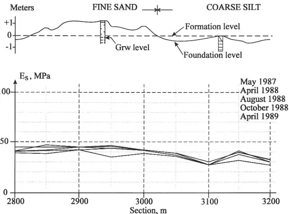
In-depth measurements during loading with FWD and rolling wheel (VTI et al.) indicate that the penetration depth is normally not greater than about 3 metres. Consequently, calculations have been made for a large number of pavements built on subgrades with various stiffness (E-modulus) and with a stiff bottom at three metres depth. From these, a regression relationship between deflection at 900 mm from the loading centre, d900, and the subgrade E-modulus, Es, has been ob-tained. The algorithm has the form:
Es (MPa) = 5,2 x 10" x
where dooo is entered in um.
The application of the algorithm is limited to "Well designed roads and measurements with a force of 50 kN".
The evaluation of the deflection measurements comprises roads from southern Sweden up to the middle part of the country during various seasons. The freezing index in this area varies from about 50 to about 1000 d°C (day degrees). Figure 1 shows an example of moduli calculated for two sedimentary soil types in a climate zone with freezing index of 500 d°C. It can be seen that there are no seasonal variations, despite the inclusion of two thaw periods (the month of April) and a frost-susceptible soil type.
Meters FINE SAND
_,|<__
COARSE SILT
Formation level
0
NL 2222 [p
L212
n n
Grw level
\
Foundation level
A
.
A
\
May 1987
i
.
;
i_ _- ---April 1988
____________________ce fo August 1988
'
|
October 1988
:
April 1989
I
i
2800
2900
3000
1
3100
3200
Section, m
Figure 1
Calculated subgrade modulus for two sedimentary soil types. Five
measurements. Freezing index 500 d°C (day degrees).
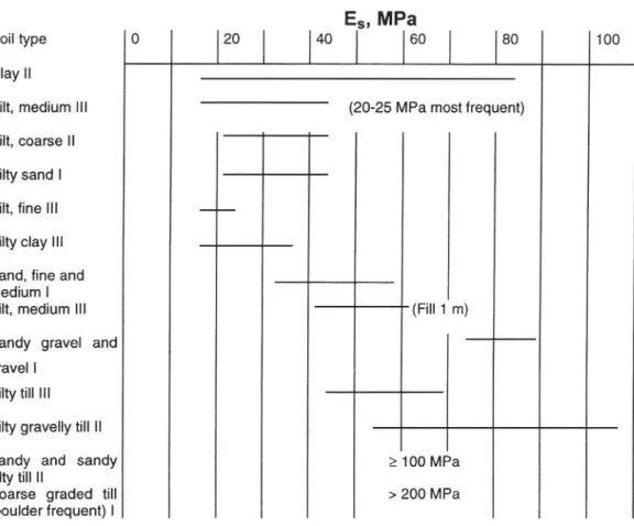
Below, Diagram 1 shows moduli and their ranges for a selection of soil types.
The following can be read from the diagram:
e The range is comparatively large for most soil types.
e Moduli for frost-susceptible and non frost-susceptible soil types overlap
each other.
e Frost-susceptible moraines have somewhat higher moduli than
frost-susceptible sediments.
e Coarse moraines show very high moduli.
The range is mainly not a consequence of seasonal variations, c.f. Figure 1. The
largest seasonal variations are approximately 20 %. In certain cases, the lowest
moduli were measured in autumn 1985 after a very rainy summer. The largest part
of the variations is explained by variations within and between measuring sites
(objects). The drainage conditions, expressed by formation position in relation to
the ground profile, provide no unambiguous explanation for the dispersion (in low
embankments, shallow cuttings, ground level).
Diagram 1 Ranges of moduli for the two groups of mineral soils, sedimentary and tills. The roman figures characterize the degree ofsensitivity to frost (I = non frost susceptible, II = medium and III = frost
susceptible).
E;, MPa
Soil type 0
I 20
I
I 40
I 60
I
I 80
100
Clay II
Silt, medium III
(20-25 MPa most frequent)
Silt, coarse II
Silty sand I
Silt, fine III
___
Silty clay III
Sand, fine and
medium I
Silt, medium I!
(Fill 1 m)
Sandy gravel and
gravel |
Silty till II
Silty gravelly till II
Sandy and sandy
> 100 MPa
silty till II
Coarse graded till
> 200 MPa
(boulder frequent) |
The higher moduli and the larger range for moraines are of an inherent nature,
partly because the material is graded, resulting in stone formation, and partly
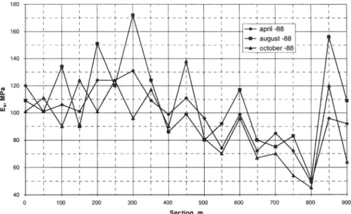
because of boulder formation (size and frequency). Figure 2 shows an example
from measurement on a moraine rich in boulders. The module varies randomly not
only along the road but also between individual measurements. The explanation
for the latter phenomenon appears to be that when making measurements on a
stretch of road, as is the case here, the individual measuring points do not coincide
exactly on different measuring occasions. The impact of FWD may thus vary
between boulder and non-boulder, causing random variations between
measure-ments.
E, , MP a 180 160 / + 4 _ ~ f _ ~ 4G ~ l _ 4 G4 4 ~ 4 H -\ | 1 1 R | | | I -+- april -88 I 1 | \ f j -=- august -88 | _T__ __T ' "-:' " -&- october -88| _- | -_ [\ ~ 7 | bd 900 Section, m
Figure 2 Variation in subgrade modulus on silty sandy moraine rich in boulders.
The above may be summarised as follows:
The seasonal variation is fairly small, at most 20 %. On the other hand, the variation within and between measuring sites is comparatively large, up to +40 %.
Within the same frost susceptibility class, the modulus of moraines is higher than that of sediments. The dispersion is also larger, especially for coarse, grained moraines. This appears to be due to the grading of the material, the presence of boulders and their size.
4.3 Discussion of variations
As stated above, the variations within and especially between objects are tangible. In addition to those already mentioned, the following more or less contributory causes may be:
24
True depth to stiff layer. (It has been assumed that the penetration depth of the FWD is three metres. However, the moraines may overlie rock. The moraines may also be very stiff even at shallow depths. An example of this is bottom moraine.
Pore pressure (positive/negative and magnitude). Groundwater level.
Water ratio.
Degree of saturation.
Difference between soil type profile according to the soil investigation and actual soil type profile.
and in the case of clays:
e Degree of consolidation. e Dry crust clay/soapy clay.
e Calcareous/non-calcareous tilly clay
Note. The position of the formation level in relation to the soil profile for the material described here is either at ground level, in a shallow cutting or on a low embankment (less than 1 metre).
In practical design, it does not appear reasonable to investigate several sub-grade parameters, such as those listed here (or a number of them). It was therefore decided that:
e The modules for moderately frost-susceptible and highly frost-susceptible soils should be differentiated according to season.
e The modules for moderately frost-susceptible and highly frost-susceptible soils should be differentiated according to groundwater level (high/low level; in those cases where the groundwater level is not known, a high level is assumed).
e The module's variation for a given soil type has in principle been chosen as the mean minus a standard deviation (higher reliability leads to a rather large dispersion in bearing capacity).
Finally, the extensive material was "structured" by collecting the soil types into groups. The general structure of the database is described below.
4.4 Table of soil type moduli
Key:
Ev = Thaw modulus, MPa
Es/h -= Summer/autumn modulus, MPa
Eb = - "Embankment modulus" (on an embankment > 1 m), MPa
GRV = Groundwater level (H: < 1 m beneath formation, D: > 1 m beneath for-mation or embankment > 1 m).
ZON = Climate zone (1-4 = 0-1200 d°C, 1-6 = whole country).
I. CLAYS AND SILTY E, Esn Ep GRV
CLAYS
fg e clay lay»
ry crust clay
35
50
45
50
50
p
H
Soft clay
(Soapy clay)
}
Geotechnical investigation
Organic soil types
Silty clay
}
20
25
H
Varved silty clay
25
35
50
D
Tilly clay
- Calcareous
No data available
- Non-calcareous
II. SILT
(Fine) silt
(Medium) silt
20
235
H
(Coarse) silt
95
35
i
p
Clayey silt
III. SILTY AND
SANDY SOILS
Silty sand
35
43
H
Clayey sand
50
50
60
D
ZON
1-4
1-4
1-4
1-4
1-4
1-4
Note: The group comprises all sediments classified as moderately frost-susceptible.
Ey, Exp Ep GRV ZON IV. FRICTION SOILS
Fine sand
Sand 50 50 50 H/D 1-6
Gravelly sand
Sandy gravel 75 75 75 H/D 1-6
Gravel
Note: The group comprises all sediments classified as non frost-susceptible.
V. TILLS
Silty till 45 60 H 1-4
Clayey silty till 60 60 70 D 1-4
Note. The group comprises all tills classified as frost-susceptible.
Gravelly sandy silty till
Gravelly silty sandy till 70 80 H 1-4
Silty sandy till 80 80 80 D 1-4
Sandy silty till
Note: The group comprises all tills classified as moderately frost-susceptible.
Gravelly sandy till 125 125 125 H/D 1-6
Coarse graded till (frequent boulders)
Note: The group comprises all tills classified as non frost-susceptible.
VI. ROCK EMBANKMENT (= Rock fill of blasted stone)
E = 150 MPa 1-6
VII. ROCK CUTTING
The pavement is built in accordance with VAG94 (the Specifications of the National Road Administration), apart from the bitumen-bound roadbase, which is the same as on adjacent sections with a soil formation.
5 Design traffic load with regard to cross-distribu-tion
To describe the cross-distribution of heavy traffic as a function of the road width, position measurements have been made on a number of roads. When determining the cross-distribution factors, the range of influence for a 50 kN wheel load with regard to strains at the bottom of the bituminous layers has been studied through theoretical calculations. For a closer study of the method and results, see [Y¥drevik, K., Notat 17-1994]. The cross-distribution factors are shown in Ch. 8 under "Heavy traffic").
Comment
The range of influence regarding deeper layers (subgrade) is greater than that regarding higher layers (the bituminous layers). However, the effect of this is offset by the design period for the formation in the system which is double the design period for the asphalt lavers.
6 Load equivalents
The term "Load equivalents" refers to the damaging effect of different wheel loads, inflation pressures, and wheel and axle configurations in relation to a well-defined reference load. However, there are no unique relations of this type, since they vary partly with thicknesses and stiffnesses (E-moduli) for the pavement layers and the subgrade response to loading. From this, it follows that the equivalency factors also vary during the year, mainly as a result of temperature variations in the asphalt layers. To take this into account, the traffic was to be described with true axle load distribution, wheel and axle configurations, inflation pressures, etc., design then being based on these unprocessed data instead of an estimated number of (N100) equivalents. This procedure would, however, have led to very extensive calculations and the accepted method based on a reference axle thus continues to be used in the system.
The reference axle in the design system is defined as a single axle with twin wheels, an axle load of 100 kN and an inflation pressure of 800 kPa. The distance between wheel centres is 300 mm.
Apart from the load itself, the load parameters which are of the greatest impor-tance for damage are tyre pressure, tyre width and wheel/axle configuration. Theo-retical calculations can be performed to quantify the damage from different load types in relation to a reference axle. This has been done to a very large extent throughout the world and is described in the literature. The value of such calcula-tions is, however, limited. The result is dependent on the condicalcula-tions assumed, not least in regard to asphalt layer thickness, while a critical factor is the tensile strain at the bottom of the asphalt layer(s). Pavement thickness (and stiffness) are signi-ficant with regard to superimposition effects in the subgrade from tandem and triple axles. Load equivalents are consequently a complex area and the dispersion in the published calculations is also very great, to some extent as a result of the criteria used (the exponential of the criteria).
In view of this, it was considered more interesting to analyse measurements of asphalt strains performed in full scale and where load, tyre pressure, wheel and axle configurations, and asphalt layer thickness respectively were varied. Such studies demand very extensive measurements, and only two projects based on this approach have been found. However, the load equivalents reported in these studies have been calculated with various criteria and have therefore been recalculated with a Swedish asphalt strain criterion, see Ch. 7. Since it is impossible to include asphalt layer thickness as a variable in a general model for calculating load equivalents, two models, for asphalt layer thicknesses of 80 and 150 mm, have been produced. Users of the design system who wish to make their own estimates of the traffic load are recommended to choose the model for 80 mm pavement thickness as it provides an estimate "on the safe side".
The model is as follows [Djarf, L., Notat 85-1995]:
0.30
EF = 1,63 x 10~ x P" x pi" x BR*"* x Konr"* (Equation 1)
with r2 = 0.974 and r2 (adjusted) = 0.97
n = 45 where
EF = equivalence factor in relation to an axle with twin wheels, load 100 kN, tyre pressure (cold) 700 kPa and tyre width 300 mm (= reference load) P = axle load, kN
pi tyre pressure (cold), kPa
BR = tyre width (shoulder width), mm
KONF wheel configuration, single = 1, twin = 2
In a design system intended for regular use, it would not appear reasonable to use general models for estimating the number of N100 equivalents for each indivi-dual road object. Instead, the models should be regarded as a tool for quantifying the importance of changes in the load conditions. In the design system, a general N100/axle factor (average number of 100 kN axles per heavy axle) has been introduced. The factor is based on extensive axle load measurements at the VTI and the National Road Administration in the middle and end of the 80s. On roads with mixed heavy traffic, the VTI reported a factor of 0.28 and the National Road Administration a factor of 0.26. These factors are based only on axle load and are calculated with an axle load exponent of 4. The model for calculating equivalence factors (Equation 1) is based on an exponent of 2.15. Extensive calculations of N10O0 for measured axle load distributions with various exponents within the scope of the STINA project [STINA, 1976] showed that N1I0OO varied fairly moderately for exponents between about 2 and 5. This is a result of the reference load being within the axle load spectrum, i.e. axle loads both below and above (overloads) 100 kN occur. Since this was the case also in the VTI/National Road Administration measurements, a factor of 0.28 N10OO0 per heavy axle was accepted as a basis.
As mentioned above, the factor 0.28 is based solely on axle load, 1.e. no atten-tion has been paid to the damage from different wheel and axle configuraatten-tions. Using Equation 1 as a guide, a 70 kN front axle and an 80 kN rear axle with wide tyres can be regarded as virtually equivalent from the damage aspect to a 100 kN axle with twin wheels.
Note: In Equation 1, the reference load has a tyre pressure of 700 KPa, which refers to the inflation pressure in a cold tyre. This applies to all tyre types and tyre pressures on which the model is based. A representative condi-tion during driving is about 10 % higher, and the reference load in prac-tice may be regarded as having a tyre pressure of 800 kPa.
In an analysis of damage from tandem axles, the result is largely dependent on the evaluation method (for an example, see Djiarf, L VTI Notat 85-1995). The most reliable result is obtained in full-scale driving experiments. For this reason, the result from the AASHO experiments has been used in correcting the N10O0
factor. (The conclusion from the AASHO experiments is that the relation in damage between tandem and single axles is 1.8:1, i.e. a 180 kN tandem axle, for example, is equivalent to a 100 kN single axle. Since two 90 kN single axles, according to the power of four rule, give 1.3 N10O0, this means that axles in tandem are less damaging than if corresponding axles are treated as single axles. This "phenomenon" is termed "the tandem effect".)
On the basis of the above and the assumption that 22.5 % of the axles in the heavy vehicle fleet are front axles, 25 % are tandem axles and 10 % of the axles, according to the National Road Administration [Johansson, O., 1991] are equipped with wide tyres (triple axles are less common in Sweden and are there-fore treated here as single axles), the corrected N100 factor is obtained as 0.49 N100 per heavy axle.
Users of the design system are also able to describe the heavy traffic as "Extremely heavy". Examples include a large proportion of log transports or gravel, heavy industrial traffic, etc. In this case, the design traffic is estimated with the factor 0.68, which is derived from axle load measurements on roads with a high proportion of log transports.
7 Design criteria
In the above, the background for the database for soil type moduli built into the design system has been described.
Analytical design requires further design criteria.
71 Asphalt strain criteria
A very large number of asphalt strain criteria exist. In Figure 3, a number of such criteria have been compiled to illustrate their dispersion.
10 log (¢*10°)
AB16t, constant load ABI16t, constant strain TAI, constant load TAI, constant strain Shell, constant strain Shell, constant load Pell Finn Monismith 3 ---I Denmark Belgium The Netherlands
2
2
3
l
«4
|
5
|
6
10 logN
Figure 3
[1988].
Comparison ofa number ofasphalt strain criteria. After Myhre, J.,
As shown by the figure, the dispersion between the criteria is very large.
Expla-nations include different test methods, failure definitions, mixes, etc. However, it
is recognised that if a criterion had been chosen, this would in every case have
required a calibration against Swedish bitumen bound roadbases and climate
conditions.
In view of this, it was decided to develop a Swedish asphalt strain criterion
based on field studies. For this purpose, three to six kilometres long sections of 12
newly built roads were chosen. The following is a summary of the development of
the asphalt strain criterion. A more detailed description is given in "Field studies
based on the asphalt strain criterion" [Djarf, L., Notat V191, 1994].
The 12 sections were followed up through annual damage surveys performed manually. In addition, deflection measurements with FWD were performed, together with vehicle classification counts and measurements of evenness and rut depth.
The deflection measurements formed the basis for estimating tensile strain at the bottom of the asphalt layer(s). The estimation used an algorithm of the following form [Jansson, H., 1992]:
g = 37,4 + 988 x dO - 533 x d300 - 502 x d600
where
£ = ustrain, tensile strain at the bottom of the asphalt layer(s)
do, 4300, 4600 = deflection at the load centre and at distances of 300 and 600 mm respectively.
The vehicle classification counts were combined with axle load measurements on the corresponding type of roads as a basis for estimating the traffic load, see Ch. 6 "Load equivalents".
The strain levels in the field which were estimated from the deflection measurements are representative of a pavement temperature of about +10°C. Fatigue tests in the laboratory at temperatures of +4°C, +10°C, and +15°C respectively [Djarf, L., Notat V191, 1994] produced a set of curves with approximately the same gradient as the field curve, but with a life about 10 % of that in the field. The curves for +4°C and +15°C have therefore been shifted in parallel to enclose the field curve at +10°C.
A traditional asphalt strain criterion, i.e. a straight line in logarithmic scales, gave a poor fit to the observations at low strain levels. To obtain the best fit, the strain exponential should be variable and dependent on the magnitude of the strain. In large strains (> 200 ustrain), cracking takes place very rapidly (low exponential) and in small strains (< 150 ustrain) progress is slow (high expo-nential). The definitions of "large" and "small" strains are naturally also dependent on traffic load. However, the former strain level can be described as a weak con-struction and the latter as a strong concon-struction. The interval between them can be described as well-designed for most (asphalt) roads.
To take account of the above and to obtain a better fit between strain level and life (cracking stage) in small strains, a simple "correction item" has been calcu-lated, after which the criterion has the following form:
N100 = 1,03 x 10° x&*"4¢ x T°" a + 2,3 x% 10" x s""), T > 0
where
N100 = number of loads with axle load 100 kN calculated as in Ch. 6 and 8
= tensile strain at bottom of the asphalt layer(s), ustrain T = pavement temperature. °C
Note: In practice, the criterion is naturally undependent on the reference load since the asphalt layer(s) are affected by the tensile strain, independent of the size of the load which has induced the strain.
As a complement to the above criterion based on pavement temperature, a corresponding criterion based on pavement stiffness has been developed. The transformation from temperature to stiffness has thereby been made with the following laboratory based relationships obtained from the drill cores taken from the road sections on which the criterion is based:
E (MPa) = 1,79 x 10⁴ x eV:9"! * °C
where
e = the base for the natural logarithm.
The criterion is thus obtained as:
N10O0 = 3,66 x 10 x&*"" xE£9"8 x (1+2,3 x 10! x
8'5 0)
where "N100" and "g" are the same as before.
7.2 Subgrade criterion
The subgrade criterion used in VAG-94 [VAG-94, 1994] has been obtained
through back calculation [Arm, M., 1992] of the middle (traffic class 4) of the
seven traffic classes in BYA-84 [BYA-84, 1984]. This was based on the
assump-tion that after certain modificaassump-tions the HMAC on gravel base pavement (GBO) in
this traffic class is correctly designed.
After modification of the N100 calculation according to Ch. 6, the criterion
evaluated in the above way has been incorporated in the system with the following
form:
N100 = 14x 10" x g?
where
N100 = equivalent number of 100 kN reference axles
g, = vertical compressive strain on the formation, ustrain.
8 Input data
The design engineer's input to the design system comprises the following information:
e Design period (10, 20 or 40 years)
e Heavy traffic (or ADT) and annual rate of increase, % e Subgrade soil, drainage conditions and groundwater level
Freezing index, d°C (day degrees) Road type
Road width, m Slope, inner verge Costs, SEK/m3
8.1 Heavy traffic
Here there are a number of possibilities depending on the design engineer's basis regarding heavy traffic and its composition. Either the number of heavy vehicles/day or the number of heavy axles/day can be specified. It is also possible to describe the heavy traffic as "mixed" or "extremely heavy". The former should be regarded as the normal case and is defined by no special types of goods being dominant on the particular object. "Extremely heavy" thus refers to the opposite, such as a high proportion of log transports, proximity to a gravel source, etc.
In certain cases, either now or in the future, there are possibilities for directly entering an estimate of the number of standard axles. Examples include rehabilita-tion/realignment of a section of road on a link where equipment for measuring axle loads has been installed or, which is more likely, that easily used mobile equipment for measuring axle loads will be developed in the future. In such cases, it is important that the calculation of the number of standard axles be performed in the way described in Ch. 6 "Load equivalents".
Finally, it is possible to specify the annual average daily traffic (AADT) alone for the traffic load. ADT refers in the accepted way to the traffic, expressed in number of vehicles, in both directions. To evaluate this, the system contains typical values for the average proportion of trucks and number of axles per heavy vehicle on different types of road. The numeric values are:
Road type "National": 14 % and 5 axles Road type "Regional": 8 % and 4.5 axles Road type "Local": 5% and 3.8 axles
(The number of N10O/axles, calculated as in Ch. 6 "Load equivalents" in mixed heavy traffic is 0.49 and in extremely heavy traffic 0.68).
The cross-distribution factors for different road widths are:
Road width, m Cross-distribution factor
7 (0.8
Motorway (MW) 0.8
9 0.7
13, wide lanes 0.65
13, hard shoulder 0.6
The traffic load during the design period is estimated on the basis of the above, together with any annual increase as specified by the design engineer.
8.2 Type of subgrade soil, drainage conditions and groundwater level
The database of subgrade soil moduli in the system, see Ch. 4, "Stiffness (E-mo-dulus) of subgrade soils", is in principle classified into six material groups depen-ding on the formation process, i.e. sediments and tills, and on the frost susceptibi-lity class. Frost susceptibisusceptibi-lity is graded on the three-level scale applied in BYA-84 [BYA BYA-84, 19BYA-84]. The database contains examples of soil types in each material group.
The database contains moduli specified for two periods, spring and sum-mer/autumn. The moduli for frost-susceptible soil types cover climate zones 1-4 (see p. 37). No differentiation between these zones has been found necessary. Moduli for climate zones 5 and 6 have not been provided. However, the values in zones 1-4 may be used for the time being. For other soil types, the specified values represent all six climate zones (the values from zone 1-4 have been extended to apply to zones 5 and 6).
Comment:
The moduli for tills are considerably higher than for sediments in the correspon-ding frost susceptibility class. This would appear logical in bearing capacity design since a graded material is less prone to deformation than a homogeneous material. This leads to thinner pavements on till subgrades if the compressive strain on the subgrade is critical as design factor. If, in the case of frost-suscep-tible material, the same pavement thicknesses are required as in sediments from the aspect of frost protection, this will be excluded from frost heave design.
The drainage conditions are specified by the design engineer as either a cutting or an embankment < 1 m, or an embankment > 1 m. The first two cases are designed similarly from the bearing capacity aspect, while in the case of an em-bankment > 1 m the formation moduli are somewhat higher.
The groundwater level is specified by the design engineer as high or low (H or L). A "High" groundwater level is defined as < 1 m beneath the formation level. The soil type moduli in this case have been set somewhat lower than for low groundwater level.
In those cases where the groundwater level is unknown, design is based on the "High" level.
In addition to soil type moduli, the database of soil type moduli contains two special cases:
1) Soft clays and organic soil types. 2) Rock embankments.
In case 1, the design engineer is referred to a special geotechnical investigation. In case 2, only one modulus has been specified (independent of embankment height). In low embankments, the type of underlying virgin soil has a certain in-fluence on total bearing capacity. However, the embankment height on a rock fill
is considerable in practice (> 1 m) and it has therefore been considered unneces-sary to introduce a differentiation of the modulus.
Comment:
A "rock embankment" is defined here as an embankment of unsorted blasted stone built for profile purposes.
Concluding comment regarding soil embankments:
If the embankment height is greater than about 2 m and the material in the em-bankment has a greater bearing capacity than the type of virgin soil on which the embankment is built (e.g. moderately frost-susceptible embankment material on a frost-susceptible type of subgrade soil), a representative soil type for the embank-ment is specified as subgrade soil type.
8.3 Freezing index
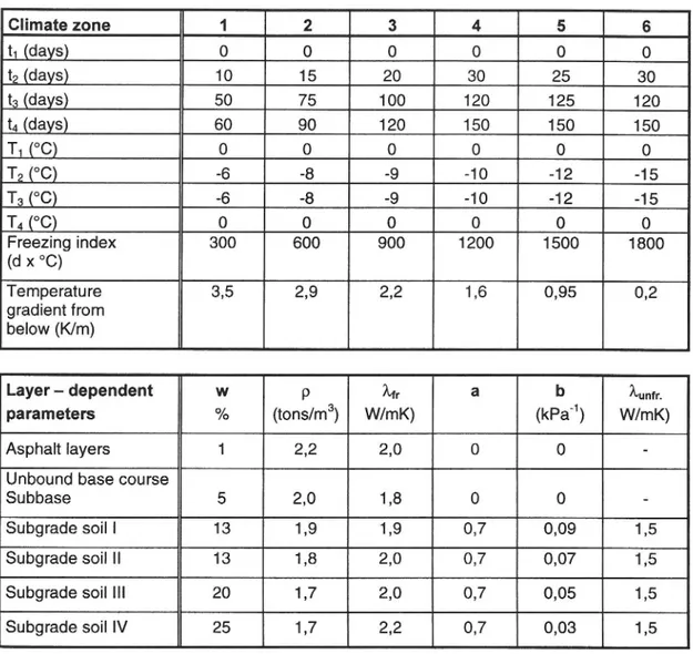
The freezing index is used to classify the particular road object in one of six climate zones, Fig. 4. The zones are identical to those in VAG-94.
The climate zones control the length of the design periods (spring, summer, autumn) and pavement temperatures during each period.
1961/62 - 88/89
Figure 4 Mean freezing index (d°C) and climate zone classification. From Tesler, A., [1991], [VAG-94, 1994].
The freezing index interval for each climate zone 1s: Zone 1: 0-300 d x °C Zone 2: 301-600 d x °C Zone 3: 601-900 d x °C Zone 4: 901-1200 d x °C Zone 5: 1201-1500 d x °C Zone 6: >1500- d x °C 8.4 Road type
Road type is specified as "National", "Regional" or "Local". The information refers to the National Road Administration's administrative classification of the road network. As shown above, it is used for estimating the heavy traffic. When evaluating the system, information on road type is also considered to be linked to bearing capacity design since the risk level in the asphalt strain criterion is controlled by the road type. Planned risk levels are 16, 30 and 50 % for "Natio-nal", "Regional" and "Local" roads respectively.
Comment:
The 16 % risk level indicates an 84 % probability that the road will achieve its intended life (or longer), etc.
8.5 Road width, inner verge and costs
As shown above, road width is required for estimating the design traffic load, N100, and also, in combination with slope of the inner verge, for determining material consumption and performing cost calculations, these being based on volume (SEK or any other currency/m3 ).
9 Material moduli, seasonal classification and bituminous layer temperatures
Fixed material moduli have been introduced in the system for the unbound pavement materials, and temperature-dependent moduli for the bitumen-bound materials. The moduli refer to materials which are approved in accordance with VAG-94.
9.1 Unbound materials
The material moduli for unbound materials are as follows (MPa):
Roadbase Sub-base Protective
layer Crushed Uncrushed Thawing Summer,
}
450
350
200
75
autumn
Comment:
e Extensive deflection measurements have not shown any seasonal variations,
e.g. for fine sand (as subgrade soil). Neither is a protective layer material
(sand, gravelly sand, fine sand, etc.) expected to show any variations,
particularly since the protective layer is in a drier position (part of the
pavement).
e An uncrushed sub-base is judged also to be "intact" regardless of season.
One reason is the same as for the protective layer. Another is that in the case
of a frost-susceptible type of subgrade soil, the sub-base lies on top of the
abovementioned protective layer.
e The material composition for a crushed sub-base does not differ greatly
from a crushed roadbase. The reason for the lower modulus is that the
sub-base is placed in thicker layers, and that the underlying layer is more
resilient than when the roadbase is compacted. (In practice, the composition
of the sub-base is occasionally also such that the compaction potential is
lower than for roadbase curves).
e Consistent with what has been said above regarding the sub-base and
protective layer, the roadbase modulus is also assumed not to decrease
during thawing. (During the initial stages of thawing, the situation with
trapped water, leading to saturation and thereby a risk of increased pore
pressure, may occur, but this is considered to be very unlikely).
9.2 Bitumen-bound material
For bitumen-bound roadbases, a modulus/temperature relationship has been
obtained in the laboratory. The relationship is based on about 200 drill cores taken
from 11 roads 0-4 years old in locations from the southernmost to the middle part
of Sweden. The relationship is as follows:
E (MPa) = 1,79 x 10⁴ x e"! *T
where
e = base for natural logarithm T = temperature in °C
The relationship is valid in the temperature range O<T<25.
For asphalt concrete, a somewhat higher stiffness may be justified. However, this difference is not taken into account in the design system, the reason being that the tensile strain at the bottom of the asphalt layers is only slightly influenced by including the difference in stiffness. The same applies to cases with a bound wearing course alone, where the underlying layers/subgrade generally control the tensile strain in the asphalt layer. The wearing course may also be assumed to be somewhat less satisfactorily compacted in this case.
9.3 Seasonal classification
As shown earlier, Sweden is divided into six climate zones, see Ch. 8.
The seasonal classification is limited to three periods, spring (thaw period), summer and autumn.
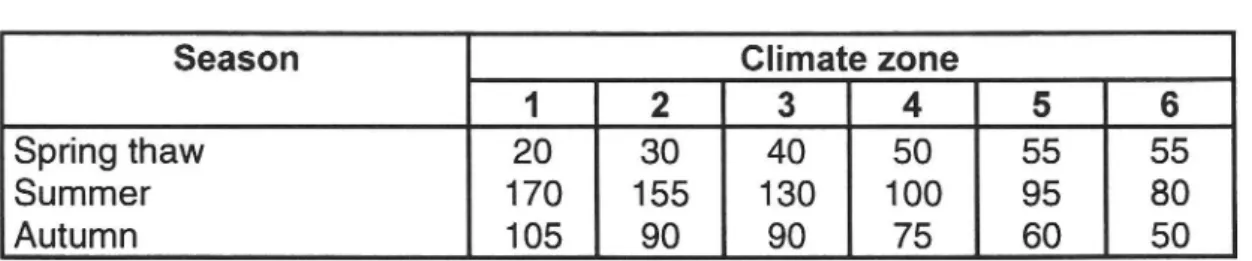
The lengths of the periods (days) in each climate zone are as follows:
Table 1 Lengths ofperiods, days
Season Climate zone
1 2 3 a 5 6
Spring thaw 20 30 40 50 55 55
Summer 170 155 130 100 95 80
Autumn 105 90 90 75 60 50
The asphalt layer temperatures for the different periods are as follows °C):
Table 2 Asphalt layer temperatures, °C.
Season Climate zone
1 2 3 4 5 6
Spring 2 2 3 5 5 5
Summer 19 18 18 18 16 15
Autumn 8 6 6 6 5 5
![Figure 3 [1988]. Comparison ofa number ofasphalt strain criteria. After Myhre, J., As shown by the figure, the dispersion between the criteria is very large](https://thumb-eu.123doks.com/thumbv2/5dokorg/4724342.124798/33.892.139.738.319.846/figure-comparison-number-ofasphalt-strain-criteria-dispersion-criteria.webp)
![Figure 4 Mean freezing index (d°C) and climate zone classification. From Tesler, A., [1991], [VAG-94, 1994].](https://thumb-eu.123doks.com/thumbv2/5dokorg/4724342.124798/38.892.246.557.514.1061/figure-mean-freezing-index-climate-zone-classification-tesler.webp)