Teresa Adeva Rodil
Edge effect on abrasive wear
mechanisms and wear resistance in
WC-6wt.%Co hardmetals
Acknowledgement
It is my pleasure to thank to my origin university "Alfonso X" to let me to be part of an exchange program for one year in Sweden. I am very grateful with the welcome of the Karlstad University, in special with the materials engineering department.
My sincere thanks to associated Proffesor. Pavel V. Krakhmalev, for all the motivation and knowledge that has given to me. In this research, a new door of the materials world has been opened to me.
I wish to thank to all the people that have help me in the diary work like Christer Burman, Anna Persson and Lars Carlsson. Thanks to my master mates Eric, Kiran and Muraly that have shown my different ways of thinking and working.
Thank you for all the people that supports me in diary life. To the people who love me and give me good energy and inspiration. Thanks to this people who are part of my heart and will never forget: Zahra, Paqui, Pedro, Danny, David, Ola and Klara.
Thanks to my family that is always close to me and thanks to my other family that are my friends: Eva, Laura and Aida. All that I am is because of you.
Teresa Adeva Rodil Karlstad University June 2006
Abstract
Wear of hardmetals is a complicated topic because the wear resistance and the wear mechanisms are influenced by microstructural factors. Although edge wear resistance has a vital importance, most of the researches made in laboratories are related to flat wear resistance using coarse abrasive paper. This situation produces problems with the prediction of abrasive wear behaviour and with the estimation of the lifetime of cutting edges of different kinds of tooling.
Several studies have been done in order to clarify edge wear behaviour. It has been published correlations of the edge toughness to the load and to the bulk fracture toughness. In those publications coarse abrasive or Vickers indenter were used.
In the present research, edge shaped specimens of WC-6wt%Co grades were investigated. In order to compare the obtained results for flat sliding and edge wear behaviour two test arrangements, pin on flat disc and edge on flat disc were employed. The specimens were tested using 120, 320, 800 and 2400 mesh SiC abrasive paper and the worn surfaces were investigated using SEM instrument to evaluate wear mechanisms. The edge wear was observed was discussed in relation to wear mechanisms investigated and correlated to the flat wear behaviour.
The obtained results showed limited applicability of the results obtained with the pin on the flat disc test arrangement for prediction of the edge wear resistance, especially in the case when size of the abrasive particles is close to the WC grain size. However, both edge and flat wear results were similar in; 1) large WC grain sized hard metals wore more than fine grain sized against coarse abrasive paper whereas the reverse occurred against fine abrasives, and 2) wear mechanisms were mainly ploughing (or grooving) for fine grain sized hardmetals in all cases, whereas wear mechanisms changed from ploughing to binder removal and carbide pull-out going from coarse to fine abrasive paper.
Contents
1. Hardmetals as a class of high-strength materials 5
1.1 Microstructure of hardmetals 5
1.2 Fabrication methods 6
1.3 Mechanical properties of WC-Co hardmetals 7 1.4 Mechanical properties at elevated temperatures 8
2. Wear mechanism 9
2.1 Abrasive wear models 11
2.2 Abrasive wear of WC-Co hardmetals 12
2.3 Archard equation 13
2.4 Erosive wear 14
3. Wear resistance in hardmetals 15
3.1 Influence of grain size on wear resistance and on wear mechanisms 16 3.2 Influence of abrasive size on wear resistance and on wear mechanisms 16 3.3 Influence of the Co content on wear resistance and on wear mechanisms17 3.4 Influence of HV and KIC on wear resistance and on wear mechanism 17
4. Aims and scopes 20
5. Experimental set up 21
5.1 Properties and microstructures of hardmetals 21
5.2 Method 22
6. Results 24
6.1 Pin on flat disc 24
6.1.1 Wear mechanisms activated in flat wear tests 26
6.2 Edge on flat disc 27
6.3 Wear mechanisms 29
6.3.1 120 SiC abrasive paper 29
6.3.2 800 SiC abrasive paper 30
6.3.3 2400 SiC abrasive paper 31
7. Discussion 32
7.1 Flat wear 32
7.2 Edge wear 34
7.3 Correlations of wear mechanisms between flat and edge wear 37
8. Conclusions 38
1. Hardmetals as a class of high-strength materials 1.1 Microstructure of hardmetals
Hardmetals are composite materials with high hardness and relatively high fracture toughness, which provide high wear resistance and rupture strength. Therefore, they are used in cutting tools industry and other applications where good wear resistance is required. Applications of hardmetals helps to decrease cost and increase the lifetime of the tools comparing to conventional height speed steel tools. Nowadays hardmetals is a wide group of composites materials, and all of them are ceramic phase (WC or TiC or TiCN) sintered together with a metallic phase (Co, Ni, Fe or mixtures).
There are two types of hardmetals: cemented carbides and cermets. When we are talking about cemented carbides we usually refer to the WC-Co composites. They have quite high toughness and good wear resistance. Cermets contain transition metals, like Ti and Ni, as a metallic binder with a TiC and TaC ceramic phase. They have a lower toughness but higher hardness and wear resistance. The difference between cemented carbides and cermets is not very clear because it is said that cermets are part of cemented carbides family [1]. Nevertheless, traditionally the WC-Co compositions called hardmetals and others named cermets.
As it is mentioned above, the classical composition of cemented carbides is WC-Co. The WC grains provide high hardness and wear resistance and the cobalt binder increases toughness. Main microstructural characteristics are related to the grain size of the WC, the interfacial bonding between the two phases and the volume fraction of the binder. A good combination of all these features brings suitable properties for each selected application. Nowadays, WC-Co components have a wide range of applications in metal and woodcutting industry, dental devices, punches, steels and non-ferrous alloys.
High hardness, high elasticity modulus, high thermal conductivity and low thermal expansion are the main characteristics of WC-Co. A disadvantage of these materials is that they cannot be used at high temperatures. When we are applying high temperatures they can deform plastically before wear occur. When plastic deformation occurs, the hard phases breaks down and the binder phase between the grains lets the grain boundary to slide [2].
1.2 Fabrication of hardmetals
Powder metallurgy is the most common process used to fabricate hardmetals. It prevents hardmetals from dentrification and decarburation. This process depends on material composition: grain sizes, binder fraction, carbon content and addition of cubic carbides. Sintering is divided in three stages. The first two belong to the solid-state and the third to the liquid phase sintering.
Fig .1. Sintering process of conventional hardmetals [3].
The sintering process contains the following stages:
1. Slow heating. The material has porosity. Gaseous reduction takes place.
2. Solid state sintering occurs below the eutectic temperature. Some amount of the hard phase is dissolved in the solid binder. A new phase tend to occur and porosity decreases.
3. Liquid state sintering starts when the temperature is above the ceramic-metal eutectic melting point. Dissolution and precipitation are the main processes.
Time and temperature has the role of determinate the hardness and toughness of the composite. The time used has to be enough to let densification occur, but not too long to
shrinkage occurs during heating and before the liquid formation. Growth inhibitors can be used too, to control the growth of the carbide grains.
Besides this process, there are others methods that produce much finer material. The problem is that there are not in industrial production yet. Among them are the spray coatings and the spark plasma sintering. They are used to improve wear resistance, corrosion, oxidation and heat. They are applied to shipboards and submarine parts.
1.3 Mechanical properties of WC-Co hardmetals.
Hardmetals combine the typical properties of ceramics such as high hardness and chemical stability with typical metal properties like high toughness and good thermal conductivity. Hardmetals are composite materials with a ceramic phase embedded into the metallic binder.
Hardness of hardmetals depends on the size of the tungsten carbide grains and on the amount of the binder phase. If the grain size of WC is decreased, the hardness increases. On the other hand, if the hardness increases the percentage of cobalt is decreased. WC grains have a hardness of 1900 to 2100 HV and the bulk goes from 800 to 2000HV.
Fig.2. Diagrams illustration the dependence of (a) hardness in the binder content and (b) hardness on grain size in WC-6%Co hardmetals [4,5].
Fracture toughness, which is related to the propagation of crack, depends on grain size and in the volumetric percent of the binder phase. It provides the ductile property of the composite. The binder plays an important role in hardmetals because it
resistance of the bulk increases. Using the fine WC grains would cause a big influence on the properties of the composite increasing the hardness and the fracture toughness. Typical dependence of the hardness with the cobalt content and the grain size are represented in fig.2.
The mean free path binder is another parameter used for the description of the WC-Co microstructure [6]. This parameter is related to the mean distance between WC grains interfaces and depends on both WC grain size and binder content, Fig.3 (a). If it is increased the volume fraction of the binder, the mean free path binder tends to increase. On the other hand, if we increase the mean free path binder, the hardness decreases, Fig.3 (b).
Fig.3. Diagrams illustration the dependence of (a) mean free path binder in the binder content and (b) mean free path binder with hardness [4,7].
1.4 Mechanical properties at elevated temperatures
The lifetime of many devices in cutting industry are limited by working conditions such as high temperatures. In the 90′s have been made several investigations about the influence of high temperatures on the mechanical properties of cemented carbides.
It has been found that are three main domains:
I) 723°K-1123°K Elastic deformation and brittle fracture. II) 1123°K-1523°K Plastic deformation of the binder. III) 1523°K-1723°K Grain boundary sliding.
Fig.4. Stress-strain curves of cermets with 18% Co depending of temperature [3].
Cobalt is the responsible for toughness of the material in domain I. When fracture occurs, it starts at the WC/WC grain boundaries and then travels through the binder and grain boundaries. In domain II, dislocation movement of the cobalt explains deformation. The number of stacking fault decreases because dislocations become mobile. The WC grains do not deform. In domain III, cobalt is found between hard phase asperities as a nanometer thick layer.
2. Wear mechanisms
The movement of one surface against another is a typical behaviour of different mechanisms and devices. Wear is a type of damage that can occur when the surfaces are moving over each other. Although it involves the removal of small amounts of material, it reduces greatly efficiently and lifetime of devices. Wear causes structural changes, plastic deformation and surface cracking. Different wear mechanisms can occur depending on the lubrication, nature of the surfaces, chemical environment and operation conditions. The main wear processes are summarized in Fig.5.
Abrasion and erosion are types of wear, produced by hard particles. In abrasion, material is displaced from the surface by hard protuberances on a counterface. Erosion is produced by hard particles striking the surface. These two types of wear will be explained more carefully in the following sections.
Fig.5. Wear processes and their main characteristics [6].
Adhesive wear is produced when two surfaces are pressed against each other. The adhesion of material on one of the surfaces is produced by attractive atomic forces that operate in the areas of contact between them. An important type of adhesive wear is fretting. It is based in an oscillatory movement between the surfaces in contact. As it is explained before, the adhesives asperities contacts are formed between the surfaces. The debris formed is oxides and fatigue cracks can be observed [8].
To describe the wear conditions that occur in metals and ceramics, we normally refer to mild and severe wear. The following table 1 collects the main characteristics of the mild and severe wear.
Table.1 Differences between mild and severe wear
Mild Severe
Produces smooth surfaces Produces rough surfaces Large metallic debris Small oxide debris
2.1 Abrasive wear models
Abrasive wear is classified as the removal of material from a surface by hard particles sliding between two surfaces. There are two main types of abrasive wear:
a) Two-body abrasion that is produced by hard protuberances in the counterface or hard particles embedded into the counterface. Some examples are grinding, cutting and machining.
Fig.6. Illustration of two-body abrasive wear.
b) Three-body abrasion that is caused by hard particles that roll or slide between the contact surfaces. An example is bearings.
Fig.7. Illustration of three-body abrasive wear, [9].
The abrasive particles produce damage on the surfaces. This is why it is important to know their properties to understand which kind of damage they can made. The abrasive particles must be harder than the material to be able to scratch it. Depending on the hardness of the abrasive following damage can be:
a) If Ha/Hs>1.2 plastic indentation is produced on the surface. It is called hard abrasion.
c) If Ha/Hs<1.2 there is no plastic indentation produce on the surface. It is called soft abrasion. It is important to mention that if Ha/Hs<<1.2, it is a good ratio for wood cutting and others applications.
Where Ha is the hardness of the abrasive particle and Hs the hardness of the surface.
Shape of the abrasive particles is also quite important because angular particles produce more severe wear than rounded. The problem is that is quite difficult to evaluate angularity of the abrasive particles but a roundness factor can be used:
2 4
P A
F = π (1)
Where A is the area and P the perimeter of the projection of the particle. If F is close to 1, then particles are more round.
Depending of the size of the particles the wear rate can vary greatly. If the coarse abrasive paper is used, the highest values of wear rate are found. If the ultra fine abrasive paper is used, lower values of wear rate are found [10].
2.2. Abrasive wear of WC-Co hardmetals
Abrasive wear can be produced by plastic deformation and brittle fracture. Normally these two mechanisms occur at the same time although there are cases where they occur separately. Plastic deformation can be observed as cutting and ploughing modes.
Fig.8. Wear by ploughing [11].
The main difference between them is that cutting mode needs high attack angle, α in the Fig. 8 (b), and ploughing low. In abrasive wear, there is only ploughing because asperities on the surface have a very low slope, so there is a low attack angle. Brittle fracture involves the presence of cracks in the surface and subsurface. The wear mechanism of plastic deformation is mainly grooving. When the abrasive particles are in contact with the surface, scratches are formed producing grooves. Brittle fracture is referred to pullout of the carbide grains, Palmqvist cracking and spalling [12]. Wear mechanisms depends on materials properties like grain size, abrasive particle size, binder content, hardness fracture toughness and properties of the counterbody.
2.3 Archard´s equation.
Archard has set his formula in 1957 and it is based on the previous work of Holm made in 1946. Archard equation is used for the analysis of wear when the deformation of the specimen is plastic. This equation gives a relation between the volume of wear, the normal load and the sliding distance. Archard´s equations is defined by:
H W K
Q= ⋅ (2)
where Q is the volume removed from the surface per unit sliding surface, W is the normal load applied and H is the hardness of the softer material. K is the wear coefficient and it is dimensional ( ) 1
Nm − and less than the unity.
The coefficient of wear is an important wear parameter that has different interpretations depending if we are in sliding or abrasive wear. In sliding wear, the coefficient of wear can be the probability of each particle to produce wear or the number of cycles before the particle is removed. The coefficient of wear in abrasive wear can be calculated using the same equation but based on different initial assumptions. It is used to measure the severity of wear.
In elastomers, the wear rate is defined by
W Q
k = where k is the specific wear
rate (mm3N−1m−1). Archard´s equation is not used in ceramics because they have brittle fracture rather than plastic. The main limitation of this equation is that it does not include material properties. On the other hand, the values of k goes from 10−4to
9
2.4 Erosive wear
Erosive wear is another kind of surface damage produced by hard particles that strikes the surface. This type of wear is very harmful because it causes imperfections very quickly and it is not easy to control.
Fig.9. Wear produced by hard particles strike to the flat surface [13].
There are three types of erosion [9]:
1) Solid particle where erosion is caused by particles in a gas or fluid. 2) Liquid drops where liquid drops produce it.
3) Cavitation where gas bubbles in the liquid can generate damage.
Erosion by plastic deformation is defined by the ratio between the mass of material removed and the mass of the particles striking the surface or by:
H U K E 2 2 ρ = (3)
where K is the coefficient of wear, ρ is the density of the material being eroded, U velocity and H hardness. This equation does not take into account the influence of the impact angle.
The main factors in erosion wear rates are impact velocity, impact angle, hardness, shape and geometry of the particle. If the impact velocity is low it may be
removal of oxides but if it gets higher the substrate is worn too. If the particles are rounded we would have ploughing.
3. Wear resistance of hardmetals
Wear resistance is one of the most important parameters on hardmetals. The main problem is that for composites there is not a very precise method to measure the wear resistance in abrasive wear. The two scientists, Khruschov and Babiched have concluded that the wear resistance of two-phase composite is defined by:
2 2 1 1 1 M M M M W V W V W R= = + (4)
where R is the wear resistance, W is wear rate and V is volume fraction [14]. The main conclusion found is that in wear behaviour in composites is predetermined by reinforcement. Zum-Gahr has contributed with the idea that composites have more than one phase . 2 2 1 1 M M M M C V W V W W = + (5)
Axén and Jacobson have made similar studies. They set an upper and lower limit where the wear resistance of composites must be. It is an intermediate mode that is between two extremes modes: equal wear (EW) and equal pressure (EP). It is based in Archard′s. The wear resistance for N phase materials is defined as:
∑
∑
Ω + − Ω = Ω i i i i i α θ α θ ) 1 ( 1 (6)In the extreme modes:
∑
= Ω = Ω N i i i 1 1 α EP mode (7) N i i iΩ = Ω∑
=1 α EW mode (8)Where Ω is the wear resistance,i αi is the fraction of area of its phases and θ is the mode coefficient. 0≤θ ≤1 [15]. We have to take in account that in this relations some factors like size, fracture toughness, distance phases are not presented.
3.1 Influence of WC grain size on wear resistance of hardmetals
WC grain size is an important parameter influencing wear resistance. The wear resistance increases as the grain size of WC is decreased. Allen [16] observed in ultra-fine grades that the wear resistance increased about twice as that of the ultra-fine grade WC-Co hardmetals.
Fig.10.Grain size vs. abrasion rate in WC-Co composites [16].
Depending on the WC grain size, different wear mechanisms occur. It has a strong relationship with the size of the abrasive particles. If the carbide particles are comparable or larger than the abrasive particles, the binder and the WC carbides interact separately with the abrasive particle. There is removal of the binder followed by pullout of the carbide grains. On the other hand, if the carbide particles are smaller than the abrasive particles the binder and the WC carbides interact at the same time with the abrasive particles [16,17,18].
3.2 Influence of abrasive size on wear resistance of hardmetals
abrasive. The ultra fine abrasive papers produce a much lower wear rate compared with coarse abrasive paper. Differences in wear rates are caused by different wear mechanisms operating if fine or coarse abrasive is used. Coarse abrasive papers usually produced plastic grooving, binder extrusion and removal, pullout of the carbide grains and cracking wear [18]. On the other hand, ultra fine abrasives papers activated removal of the binder followed by pullout of the carbide grains wear mechanisms [17,19].
3.3 Influence of binder content on wear resistance of hardmetals
Binder content also influences the wear resistance. The abrasive wear resistance of the WC-Co composite is decreased with the increase in cobalt content.
Fig.11. Grain size vs. abrasion rate in WC-Co composites [4].
Depending if we have low or high cobalt content, different wear mechanisms would occur. In low cobalt contents hardmetals, the binder and the WC grains can wear at the same time. In this the WC grains control the wear resistance. In high cobalt contents, there is ploughing of the binder, fracture and pullout of the carbide grains. In this case the rate-controlling step is the wear of the cobalt binder [20]. If we increase the binder content the wear rate increases and the wear resistance decreases [21].
3.4 Influence of hardness and fracture toughness on wear resistance of hardmetals
Hardness and fracture toughness are important mechanical properties influencing wear resistance. Hardness is the resistance against indentation and fracture
toughness is the resistance against a crack growth. A good combination of both gives a better lifetime and performance of the hardmetal.
The hardness is a parameter that is often related to the WC grain size. As the grain size of the WC grain is decreased hardness is increased. If we increase the hardness the wear resistance is also increased, Fig.12.
Fig.12. Hardness vs. abrasion rate in WC-Co composites [16].
Although hardmetals of WC-Co influences wear rates, the wear mechanisms operating depend also on the hardness of the abrasive.
Fig.13. High and low wear levels with same binder composition and grain size but different binder contents. Here we can observed the differences in wear resistance before and after the 1.2 of Ha/Hs. Ha refers to hardness of the abrasive and Hs to hardness of the surface [19].
In the case of hard abrasion (Ha/Hs>1,2) there is fracture of WC grains and plastic deformation in the binder and WC phase. In the case of soft abrasion (Ha/Hs<1,2) the wear rate is lower and the mechanism different. There is removal and then extrusion of the binder phase. Then there is a fragmentation of the carbide grains until the whole grain is removed [19].
There is a correlation in conventional hardmetals between wear volume and hardness. It is expressed by:
BH A V
Log10 = −
Where V is the wear volume, H the hardness of the hardmetal and A and B are constants.
Fracture toughness is influenced by grain size and in the volumetric percent of the binder phase. It provides the ductile property of the composite. In Fig.14 (a) we can observe that as the fracture toughness is decreased the wear resistance increases. On the other hand in Fig.14 (b), as we increase the hardness the fracture toughness decreases.
Fig.14. Diagrams illustration the dependence of (a) fracture toughness with wear resistance and (b) fracture toughness with hardness.
Wear resistance is increased if hardness is increased or fracture toughness is decreased. The problem is that if hardness is increased at the same time that toughness is decreased brittleness is produced. So, for each application we have to find the best combination of hardness and fracture toughness to improve the lifetime of the hardmetal. Otherwise, we would have a brittle material.
4. Aims and scopes
Wear of hardmetals is a complicated problem due to there is many microstructural factors that affects the wear resistance and the wear mechanisms. Often, the test arrangements used for the evaluation of wear resistance in laboratories are not related to edge wear resistance, although geometry and test conditions differ dramatically.
Several researches have been done in order to clarify behaviour of edge. Important findings on correlation of edge toughness to the load and bulk fracture toughness have been published. Nevertheless, in those publications coarse abrasive or Vickers indenter was used. In other words, interaction zone exceeded features of microstructure significantly.
In the present research, the edge shaped specimens of several WC-6wt%Co grades were investigated. In order to compare results for flat sliding and edge behaviour, two test arrangements were employed: pin on the flat disc and edge on the flat disc. The specimens were tested using 120, 320, 800 and 2400 grades of SiC abrasive paper and the worn surfaces were investigated using the SEM to evaluate wear mechanisms operative. The edge wear observed were discussed in relation to wear mechanisms investigated and correlated to the flat wear behaviour. The obtained results showed limited applicability of the results obtained with the pin on the flat disc test arrangement for prediction of the edge wear resistance, especially in the case when size of abrasive particles is close to the WC grain size.
5. Experimental set up
5.1 Properties and microstructures of hardmetals.
The variables factors influencing abrasive wear are the grain size of the carbides and the grain sizes of SiC papers. In this research, four grades with the same amount of cobalt content but different WC grain sizes were examinated. Each specimen had a length of 2 cm and a diameter of 3.2 mm. Each one was rubbed for 90-95 meters on different SiC papers (800, 320 and 120). Worn volume was measured after about each 10m step.
Table 2. Size of the abrasive particles
Abrasive paper Size of the abrasive particle (µm) 800 22.8
320 46.0
120 106.0
The properties of the materials and their microstructural features are presented in table 3 and Fig.15.
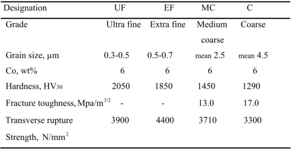
Table 3. Properties and designation of materials used
Designation UF EF MC C Grade Ultra fine Extra fine Medium Coarse coarse
Grain size, µm 0.3-0.5 0.5-0.7 mean 2.5 mean 4.5
Co, wt% 6 6 6 6 Hardness, HV30 2050 1850 1450 1290
Fracture toughness,Mpa/m3/2 - - 13.0 17.0 Transverse rupture 3900 4400 3710 3300 Strength, N/mm 2
(a) (b)
(c) (d)
Fig.15. Microstructure of the tested specimens, (a) UF, (b) EF, (c) MC and (d) C. Bright phase corresponded to the WC and black (dark) phase to the Co binder.
5.2 Method
The specimens were polished carefully in order to be able to observe microstructures in the scanning electron microscope, SEM, and avoid scratches. It was followed three main steps:
1) Piano wheel diamond at 50N during 6 minutes in water.
2) Allegro wheel diamond at 45N during 5 minutes using 6µm diamond spray with blue lubricant.
3) Dur wheel at 20N during 8 minutes using 3µm diamond paste with red lubricant.
Abrasive wear test were carried out using pin on flat disc and edge on flat disc arrangements. The flat specimen’s surface was placed parallel to the abrasive surface
and a load of 40N was applied. The disc, covered with abrasive paper, rotated perpendicular to the holder to achieve a final sliding distance of about 90 meter.
Fig.16. Sketch of the set up test of flat wear.
Two different methods were used to measure the wear rate in flat surface. First, with ultra fine abrasive paper (800 SiC), an indentation was made on the tested surface of the specimen. Optical profilemeter was used to ascertain the differences of height after each 10 meters. Worn volume was calculated from decrease of the indentation depth. A mean value of 15 measurements was used for calculations of the worn volume. Secondly, with 120 SiC and 320 SiC papers, the micrometer was used to measure the differences of length of the specimen after sliden.
For the edge on discs tests, the specimens were polished in both sides to produce 90º degrees. Then, mounted in plastic in a horizontal position to obtain an angle of 45 degrees between the abrasive surface and the specimen side, and loaded 2N normal load. In the edge on flat disc experiments, wear rates were characterized measuring worn width on the edge of the specimen. The samples were slide up to 27 meters in total sliding distance. The worn surfaces were characterized in SEM to investigate wear mechanisms and worn width after certain sliding distances.
Fig.17. Sketch of the test set up of edge wear.
Worrn width 90° Normal load S p ecimen Ab rasive p ap er R otation wh eel S lid d in g d irection
0 10 20 30 40 0 20 40 60 80 100 120 Sliding distance, m W o rn vo lu me, mm3x10-4 C MC EF UF 6. Results
6.1 Pin on flat disc.
Wear plots were drawn for each specimen under the same load conditions. Each specimen was tested with three different SiC abrasive paper (120, 320 and 800 SiC grit). In all the grades were observed a linear dependence between the worn volume and the sliding distance. Each grade showed ”Archard´s” type behaviour Q=K⋅W, where
the Q is wear rate, the K the wear coefficient and the W the applied load.
If the120 paper was used, Fig.18, the highest wear rate were observed for the C grade and the lowest for the UF grade. On the other hand, when the 800 paper was utilized, Fig.20, the C grade showed the lowest wear rate and the EF grade showed the highest one. If the 320 paper was used, Fig.19, the lowest wear rate was still observed for the C but the highest changed for the MC grade.
0 0,2 0,4 0,6 0,8 0 20 40 60 80 100 120 Sliding distance, m Wo rn vo lu me, mm3x10-4 C MC UF EF 0 2 4 6 0 20 40 60 80 100 120 Sliding distance, m W o rn vo lu me, mm3x10-4 C EF MC UF
Fig.19. Wear loss vs. sliding distance at 40N and 320 SiC abrasive paper.
Fig.20. Wear loss vs. sliding distance at 40N at 800 SiC abrasive paper.
Since straight lines fit properly all the diagrams, it was possible to describe wear loss as a function of sliding distance in y=ax type equation. The “a” coefficient would correspond to the wear rate and was used for evaluation of the wear resistance in the future discussion. Trend lines were drown for all the experiment data with R2=0.95.
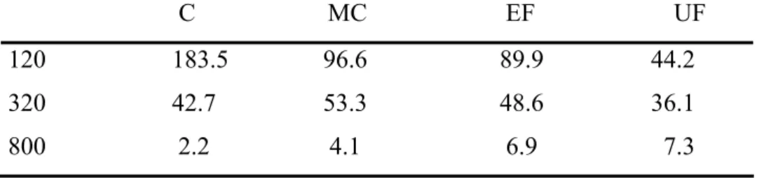
Table 4. Wear rates for each specimen depending on the abrasive paper
C MC EF UF 120 183.5 96.6 89.9 44.2 320 42.7 53.3 48.6 36.1 800 2.2 4.1 6.9 7.3
From the values presented in table 4, it is seen that generally wear rates increases dramatically as the SiC abrasive size increased. Nevertheless, this influence is much more pronounced for the C grade, which showed increase in wear rate two in orders of magnitude with increase of SiC grain size from 22.8 to 106.0 µm (Tab. 2). Although the same trend was found for finer grades growth of wear rates is not so significant for those materials.
6.1.1 Wear mechanisms at flat wear.
Worn surfaces were examinated in the SEM in order to evaluate operative wear mechanisms. To illustrate most typical wear mechanisms, the worn surfaces observed for the C and UF grades were presented in Fig.21. In the MC and EF grades, intermediate wear patterns were observed. In the MC grade, the wear mechanisms were closer to the C, while in the EF grade behaved rather similar to the UF grade.
(c) 320 SiC (d) 320 SiC
(e) 800 SiC (f) 800 SiC
Fig.21. Worn surfaces observed in the UF (a), (c) and (e) and in the C grade (b), (d) and (f) grades after 90 meters sliding against 800, 320 and 120 SiC abrasive paper.
Ploughing was the main wear mechanism observed for the UF grade, Fig.21 (a), (c) and (e). This wear mechanism was found independent on the abrasive size and observed for all the abrasive papers. In the case of the C grade, wear mechanisms activated were different, depending on the SiC abrasive paper utilized. If the 120 SiC paper was used, the wear mechanism were ploughing and fracture of the WC grains. On the other hand, if the 800 SiC paper was used, removal of the binder followed by pullout of the carbide grains was observed, Figs. 21 (b) and (f). If 320 paper was utilized, the surface pattern has a mixed character and features of ploughing, WC fracture and binder removal can be found.
6.2 Edge on flat disc
0 400 800 1200 0 500 1000 1500 2000 2500 3000 Sliding distance, cm Worn width, µm UF C 0 100 200 300 400 0 500 1000 1500 2000 2500 3000 Sliding distance, cm Wor n width, µm UF C
found that wear mechanisms depended on abrasive grain size and WC grain size (at a constant volume of cobalt). Width of the edge was measured in the SEM to evaluate the relative wear resistance.
A big increase in the wear rate at the beginning stage of the sliding distance was observed for all the grades, Fig. 22, 23 and 24. Then, the wear rate still increased but with a lower rate. Such a parabolic character of the wear diagrams was found to be typical for all the grades.
The worn width vs. sliding distance diagrams were not recalculated to worn volume vs. sliding distance diagrams. It has not been done due to the width vs. sliding diagrams are more visual and clear for analysis. Therefore, the terms higher wear rates and higher wear volume used below corresponded to the wider worn width observed after certain sliding distance.
0 25 50 75 100 0 500 1000 1500 2000 2500 3000 Sliding distance, cm Wor n width, µm UF C
Fig.23. Worn width vs. sliding distance at 2N and 800 SiC abrasive paper.
Fig.24. Worn width vs. sliding distance at 2N and 2400 SiC abrasive paper.
If the 120 SiC paper was used, the highest wear rates corresponded to the C grade and the lowest to the UF grades. Otherwise, when 2400 SiC paper was used, the C grade showed the lowest wear rate and the UF grade showed the highest one. If the 800 SiC paper was used, at the beginning stage of the sliding the UF was the grade with the lower wear rate but as we increased the sliding distance, the C grade becomes the one with the lower one. These changes in wear rates led to crossing of the diagrams, as seen in Fig.23.
6.3 Wear mechanisms.
6.3.1. 120 SiC abrasive paper.
Wear mechanism were investigated by analysis of the worn surfaces in the SEM. Fig.25 summarizes the wear mechanisms observed for the UF and C grades slid against 120 SiC abrasive paper. Grooving and some chipping were seen at the beginning stages for the UF grade on 120 SiC paper. After a long sliding distance of 2750 cm there was only grooving was observed on the surface of the UF specimen, Fig. 25 (a) and (b). Ploughing was the main wear mechanisms observed for all the sliding distance for the C grade, Fig. 25 (c) and (d).
(a) (b)
(c) (d)
Fig.25. (a) and (b) corresponded to the UF grade in 120 SiC paper, (c) and (d) corresponded to the C grade in 120 SiC.
6.3.2 800 SiC abrasive paper.
If the 800 SiC paper was utilized, ploughing was found the main wear mechanisms at all the sliding distance for the UF grade, Fig.26 (a) and (b). Pullout of the WC grains was observed, at the beginning stages of sliding for the C grade. Morphology of the worn surface was changed for the C grade after a long sliding distance of 1275 cm and ploughing and fracture of the WC grains were revealed the main wear mechanism, Fig. 26 (c) and (d). (a) (b) UF, 1.5cm C, 1.5cm UF, 2750 cm C, 2750 cm UF, 0.5cm UF, 1275cm
(c) (d)
Fig.26 (a) and (b) corresponded to UF in 800 SiC paper, (c) and (d) corresponded to C in 120 SiC paper.
6.3.3 2400 SiC abrasive paper.
When the 2400 paper was used, ploughing was the main wear mechanisms found in all the sliding distance in the UF grade, Fig. 27 (a) and (b). In the case of the C grade, at the beginning stages some rounding and binder removal followed by pullout of the WC grains was observed. After a long sliding distance of 1275 cm removal of the binder followed by pullout of the WC grains was seen, Fig. 27 (c) and (d).
(a) (b) (c) (d) UF, 0.5cm C, 0.5cm UF, 1275 cm C, 1275 cm C, 0.5cm C, 1275cm
Fig.27. (a) and (b) corresponded to UF in 2400 SiC paper, (c) and (d) corresponded to C in 2400 SiC paper.
Generally it seen that increase in SiC grit rapidly increases the total worn volume (width). If 2400 SiC paper utilized, the maximal worn width was observed in the UF grade. From the values presented in table 5, it is observed worn width increases as the SiC abrasive size increased. This influence is much bigger for the C grade than for finer grades.
Table 5. Worn width for each specimen depending on the abrasive paper after 2750 cm of sliding distance C UF 120 1161.3 516.2 800 342.5 369.8 2400 59.7 72.6 7.Discussion 7.1 Flat wear
As it is well-known from the literature, wear rates are influenced by the binder content, grain size of the carbide and grain size of the abrasive. In our test, the cobalt content was 6wt% in all the grades. In general models of abrasion [14], it has been shown that the wear rate is linearly proportional to the sliding distance like occurred in Fig.18, 19 and 20. These straight lines were related to the “ Archard´s ” type behaviour
W K
Q= ⋅ , where the Q is the wear rate, K the wear coefficient and W the applied load
C MC EF UF 800 320 120 183,5 96,6 89,9 44,2 42,7 53,3 48,6 36,1 2,2 4,1 6,9 7,2 0 20 40 60 80 100 120 140 160 180 200 W ear rate, mm3/ m
Fig.28. Wear rates of each specimen during abrasive wear in three different abrasive papers.
It is seen, in Fig.28, that WC grain size and abrasive grit size influenced wear rate significantly, as it has been predicted in [17]. If 120 paper was used, the C grade demonstrated the worst wear resistance comparing to the others. As WC grain size decreases, the wear rate decreases also, so that the ultrafine grade had wear rate of about 5 times lower than that for the C grade. According to Allen, the wear resistance of ultra fine grades was up twice that any conventional grades [16]. If 320 paper was utilized, wear rates were about the same and the lower observed were for the C and the UF grades. If the 800 paper was employed, the situation is the opposite to the one if the 120 paper was used. The highest wear rate was observed for the UF grade, while the C grade demonstrated better performance. As it has been observed in other investigations, if the WC grain size was increased in fine SiC abrasive papers the wear resistance increased [17,22,24].
The microstructural examination was carried out in the SEM. Ploughing was the wear mechanism observed for the UF grade in all the SiC abrasive papers, Fig. 19 (a), (c) and (e). This behaviour might be explained taking into account that the SiC abrasive particles are larger than the WC grain size in all the cases. Since features of microstructure are finer than size of SiC particles, there were no separated interaction
composite behaved quite homogeneously and ploughing was the main wear mechanisms. Similar behaviour was observed in [18].
For the C grade, wear mechanisms were different and depended on the SiC grain size. If the 120 SiC paper was used, ploughing was the main wear mechanisms observed, Fig.21 (b). As the abrasive paper was changed to the 800 grits, removal of the binder followed by pullout of the WC grains was activated. Changes in wear mechanisms also can be related to the size of the abrasive. If the 120 SiC paper was utilized, abrasive size exceeded WC grain size and ploughing was activated. Similar behaviour was observed in [17], where hardmetals on microscale abrasion were tested.
7.2 Edge wear
Edge wear is influenced by the binder content, abrasive size particles, tungsten carbide grain size [25] and geometry of the edge.
Fig.29. Scheme of the possible interactions of abrasive particles with the edge, (a) abrasive is smaller than the WC grains (b) abrasive is larger than the WC grains.
If the abrasive particle was smaller than the WC grains, the abrasive particle may interact separately with the binder and WC grains. Depending of the localization of the interaction of the abrasive particle on the edge, different wear mechanisms can be activated, Fig. 29 (a). Binder removal, rounding and pullout of the WC grains could be observed in the case of fine abrasive. If the abrasive particle was larger than the WC grains, the binder and the WC grains interacted at the same time with the abrasive particle. Then, ploughing might be the main wear mechanisms, Fig. 29 (b).
Experimental results obtained in the present research showed that at the beginning stages, if the 120 SiC paper was used, ploughing and chipping were observed on the edge of UF specimen, Fig.25 (a). Chipping was due to brittle fracture and caused by mechanical loading. At the sharp edge of the specimen, there was not enough strength and therefore, flaking damage was produced. Ploughing was the main wear mechanism observed after a long sliding distance in the UF grade, Fig. 25 (b). In the case of the C grade at 120 SiC paper, ploughing was observed in all the sliding distance, Fig. 25 (c) and (d). Following the discussion above, such behaviour is typical for the case when abrasive is larger than the WC grain size.
Fig.30 Wear by chipping. Abrasive particles caused a crack running parallel and towards the edge to form a flake [26].
If 2400 SiC paper was used, the UF grade showed ploughing in all the stages of the sliding distance, Fig. 27 (a) and (b). The wear mechanisms observed at the beginning stages for the C grade and 2400 SiC paper was binder removal and rounding and pullout of the WC grains, Fig. 27 (c). The C grade at 2400 SiC paper showed removal of the binder followed by pullout of the carbide grains after a sliding of 1275 cm, Fig. 27 (d).
Comparing the 120 and 2400 SiC paper it was found similarities on wear rates in the UF and C grades in flat and edge wear. If 120 SiC paper was used, the wear rate of the C grade was higher than for the UF grade for edge and flat wear. In the case of the 2400 SiC paper, the wear rate of the C grade was lower than for the UF grade for edge and flat wear. These similarities may be caused because the wear mechanisms found were similar for edge wear after a long sliding distance and flat wear. So, if we are
Abrasive particle
Flake Edge
using fine and coarse abrasive paper we have the chances to predict qualitatively wear rates and wear resistance in the UF and C grades.
A different situation was found if the 800 SiC paper was used. There is one point where the UF and C grade showed the same worn width at the same sliding distance, Fig. 31. At the beginning stage, the C grade had a big increased in the worn width due to pullout of the WC grains was activated. After 1200 cm of sliding distance for the C grade, the worn width increased in a lower rate because ploughing was activated. In the case of the UF grade in 800 SiC paper, ploughing in all the sliding distance was observed.
Comparing the UF and the C grade for the 800 SiC paper, it was not found similarities in wear rates for edge and flat wear. So, if we are using abrasive particle size similar to the WC grain size, as it is in the case of 800 SiC for edge wear and 320 SiC for flat wear, wear mechanisms activated are not the same. Is not possible to make any prediction about wear rates.
0 100 200 300 400 0 600 1200 1800 2400 3000 Sliding distance, cm Wor n width, µm UF C
Fig.31. Worn width and edge wear mechanisms for the UF and C grade on 800 SiC abrasive paper.
There is an insufficient knowledge about edge wear made by previous research. Until now most of the studies about wear damage has been done in flat wear.
Pullout of WC grains
Ploughing
Ploughing
7.3 Correlations of wear mechanisms between flat and edge wear
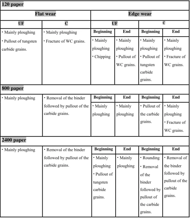
Table 6. Wear mechanism depending of abrasive, carbide grains and type of wear
120 paper
Flat wear Edge wear
UF C UF C
Beginning End Beginning End
· Mainly ploughing · Pullout of tungsten
carbide grains.
· Mainly ploughing
· Fracture of WC grains. · Mainly
ploughing · Chipping · Mainly ploughing · Pullout of WC grains. · Mainly ploughing · Pullout of tungsten carbide grains. · Mainly ploughing · Fracture of WC grains. 800 paper
Beginning End Beginning End
· Mainly ploughing · Removal of the binder
followed by pullout of the carbide grains. · Mainly ploughing · Mainly ploughing · Pullout of the carbide grains. · Mainly ploughing · Fracture of WC grains. 2400 paper
Beginning End Beginning End
· Mainly ploughing · Removal of the binder
followed by pullout of the carbide grains. · Mainly ploughing · Pullout of tungsten carbide grains. · Mainly ploughing · Rounding · Removal of the binder followed by pullout of the carbide grains. · Removal of the binder followed by pullout of the carbide grains.
8. Conclusion
In pin on flat disc experiments under 40N of load and 90 meters of sliding distance we can conclude that:
1. The wear rates depend on the WC grain sizes and on the grain size of the abrasive. If the fine SiC abrasive was used, the C grade demonstrated better performance. On the other hand, if the coarse SiC abrasive was used, the UF grades behaved better.
2. The wear rates depended on the abrasive size. The wear rates observed for the C grades increased to two orders of magnitude as the fine abrasive was changed to the coarse one. Similar but not too much pronounced trend was found for the UF grades.
3. In our investigation, the plastic deformation, grooving and fracture carbides grains were found the main wear mechanisms for the C grades, if the 120 grit SiC abrasive paper was used. Removal of the binder followed by pullout of the carbide grains were detected typical for the C grade in the case of 800 grit abrasive was utilized. The UF grade demonstrated the same ploughing wear mechanism operative as for fine and coarse abrasive.
In edge on flat disc experiments under 2N of load during 27 meters we can conclude:
4. If fine abrasive paper was utilized, similarly to the flat sliding conditions, the coarse grades demonstrated better wear resistance than the ultra fine ones.
5. If coarse abrasive paper was utilized, similarly to the flat sliding conditions, the ultra fine grades demonstrated better wear resistance than the coarse ones.
6. It abrasive size was comparable to features of microstructure, at the beginning of
sliding the coarse grades demonstrated higher wear rates due to activation of the WC grain pullout. Further sliding led to changes in wear mechanism to the binder removal that led to decrease in wear rates. Ploughing was found the main wear mechanism in ultrafine grades aver all the sliding distances. Changes in wear mechanisms observed in the coarse grades led to crossing of the wear diagrams after about 1200 cm sliding.
References
[1] D.Mari, S.Bolognini, T.Viatte, W.Benoit, Study of mechanical properties of TiCN-WC-Co hardmetals by the interpetration of internal friction spectra. International Journal of Reflactory Metals and Hard Materials 19 (2001) 257-265.
[2] Östberg, Buss, Chistensen, Norgren, Andrén, Mari, Wahnström, Reineck, Effect of TaC on plastic deformation of WC-Co and Ti(C,N)-WC-Co. International Journal of Reflactory Metals 24 (2006) 145-154.
[3] Kathalina Buss, High temperature deformation mechanisms of cemented carbides and cermets. École Polytechnique Federale de Laussane, Thése N°3095 (2004) 20-25. [4] O´Quigley, Luyckx, James, An empirical ranking of a wide range of WC-Co grades in terms of their abrasion resistance measured by the ASTM standart B 611-85 test. International Journal of Reflactory Metals and hard materials 15 (1997) 75-79.
[5] Jacob Sukumaran. Wear mechanisms of wedge-shaped hardmetals abraded by SiC grits at various loads. Engineering Materials, Master Thesis. Karlstads universitet (2005).
[6] Materials to resist wear. A Guide to their Selection and Use. Lansdown , Price. University College, Swansea, K. Pergamon Press (1986) 126.
[7] Jia, Fischer, Gallois. Microstructure, hardness and toughness of nanostructured and conventional WC-Co composites. Nanostructured materials 10 (1998) 875-891.
[8] Wear. Materials, Mechanisms and Practice. Editor Gwidon W Stachowiak. Wiley. Tribology in Practice Series (2005).
[9] Glaser, Erickson, Dufrane and Kannel, Balteile Columbus, Tribology: The science of combating wear. University of Ohio (1994).
[10] Hutchings, Tribology: Friction and wear of engineering materials. Departament of Materials Science and Metallurgy University of Cambridge 164 (1992).
[11] Roberts, Wear, Surface engineering. http://www-sgrgroup.materials.ox.ac.uk/ lectures/tribology/wear.pdf (2003).
[12] Gant, Gee, Roebuck, Rotating wheel abrasion of WC/Co hardmetals. Wear 258 (2005) 178-188.
[13] Surface engineering and wear. Editor Dawis, Woodhead publishing (2001).
[14] Gun Y. Lee, C.K.H.Dharan, R.O. Ritchie, A physically-based abrasive wear model for composites materials. Wear 252 (2002) 322-331.
[15] Axen, Lundberg, Abrasive wear in intermediate mode of multiphase materials. Triboloby international 28 (1995) 523-529.
[16] Allen, Sheen, Williams, Pugsley, The wear of ultrafine WC-Co hard metals. Wear 250 (2001), 604-610.
[17] Shipway, J.J. Hogg, Dependence of microscale abrasion mechanisms of WC-Co hardmetals on abrasive type, Wear 259 (2005) 44-51.
[18] Gant, Gee, Abrasion of tungsten carbide hardmetals using hard counterfaces. International Journal of Reflactory Metals and Hard Materials 24 (2006), 189-198. [19]. Herr, Sailer, Sockel, Schulte, Feld, Prakash, Characterization of wear properties of ultrafine-grained hardmetals using a special abrasive wheel test. International Journal of Reflactory Metals and Hard Materials 19 (2001) 371-379.
[20] Gant, Gee, Wear of tungsten carbide-cobalt hardmetals and hot isostatically pressed high speed steels under dry abrasive conditions, Wear 251 (2001) 908-915. [21] Shopway, Hogg, Dependence of Microscale abrasion mechanisms of WC-Co hardmetals on abrasive type. Science Direct, Wear 259 (2005), 44-51.
[22] Pirso, Viljus, Letunovits. Friction and dry sliding wear behaviour of cermets. Science Direct, Wear 260 (2006) 815-824.
[23] Hu, Li, Llewellyn. Computational investigations of microstructural effects on abrasive wear of compostes materials. Science Direct. Wear 259 (2005) 6-17.
[24] Gahr. Wear by hard particles. Tribology international, Vol 31. 587-597 (1998). [25] Morrell, Gant. Edge chipping of hard materials. International journal of reflactory metals and hard materials. (2001) 293-301.
[26] Morrell, Gant. Edge chipping of hard materials. International journal of reflactory metals and hard materials. (2001) 293-301.
[27] Shipway, J.J. Hogg, Wear 259 (2005) 44-51.
[28] Scieszka. Edge failure as a means of concurrently estimating the abrasion and edge fracture resistance of hard-metals. Tribology international. (2005) 1-9.
[29] Scieszka. The wear transition as means for hardmetal fracture toughness evaluation. International journal of reflactory metals and hard materials. (2001) 101-108.
![Fig .1. Sintering process of conventional hardmetals [3].](https://thumb-eu.123doks.com/thumbv2/5dokorg/4593831.118094/6.892.160.735.332.737/fig-sintering-process-conventional-hardmetals.webp)