INTERNATIONAL DESIGN CONFERENCE - DESIGN 2016 Dubrovnik - Croatia, May 16 - 19, 2016.
TOWARDS A PLATFORM APPROACH
SUPPORTING THE INTERFACE BETWEEN
TECHNOLOGY- AND PRODUCT DEVELOPMENT
S. E. AndréKeywords: product development, technology development, interface, platform, engineering design
1. Introduction
Suppliers in the automotive industry is continuously faced with the challenge of conducting efficient development and manufacturing of products and at the same time offer a high degree of customization. This has been shown to be an immense challenge since future requirements are unknown which in turn makes it hard to be proactive in the development. One other factor that amplifies the challenge is the splitting of technology development (TD) and product development (PD). TD often has a more long term goal of supplying a to some extent uncertain future market with new technology, whereas PD is of more short term character fulfilling specific customer requirements. It is suggested that the splitting of TD and PD can decrease the risk towards a customer [Säfsten et al. 2014]. This splitting introduces an interface between TD and PD that is in need of a strategy. Nobelius [2004] points to three aspects of this interface: (1) Strategic and operational synchronization. (2) Transfer scope, which refers to the decisions of what to transfer and deals with concepts, test results and recommendations. (3) Transfer management that deals with how the transfer is done. Lakemond et al. [2007] emphasises that technology transfer must take place in a physical hand over and an understanding of each other’s work must be developed. Cooper [2006] and Högman [2011] proposes using a stage gate process to manage TD. The process covers stages and gates from discovery of a new technology to a developed product. Also Eldred et al. [1997] proposes a high level process to go from TD to PD. The authors have in common that a technology transfer step is needed in the interface between TD and PD. Figure 1 shows the technology transfer step adapted from [Eldred et al. 1997].
As presented, much research has been done about TD and the interface between TD and PD. However, it is often viewed and described from a management perspective and does not in detail describe what goes on in the interface. What is in detail transferred from TD to PD remains unanswered. How can a novel technology be described in order for the designers to use the result during PD? How is the design space of the technology communicated so that the designers can understand the technology’s ability to adapt? This research will scratch the surface of these problems by using an example taken from the automotive industry as well as propose a platform approach to aid some aspects of the TD and PD interface.
Platform thinking has been described in literature as a way to increase reuse and commonality. Early descriptions of product platforms focuses on efficiently providing the market with a product variety at the same time keeping the internal variety low [Meyer 1997]. Recent research have focused on platforms with a more abstract definition aiming to reuse more of the skills and knowledge (assets) created in a company.
Figure 1. The technology transfer process - adopted from [Eldred et al. 1997]
This paper elaborates on one example of platform content by using simple 1 dimensional (1D) simulations of property models early in TD and to describe the outcome of theses simulations in a format readable to the designers in the subsequent PD. 1D indicates using time as the main variable which is suitable for simple dynamic simulations. 1D models are used due to their relative simplicity which enables them to capture characteristics without having designed a detailed 3D geometry. The property models and their related descriptions aim to transfer knowledge created during TD and supply it to the designers in PD in order to support the interface between TD and PD. During these early phases it is also proposed to use a Set-Based approach by generating several technology concepts and simulate these while maintaining a large design space as well as to use trade-off curves. With Set-Based Concurrent Engineering (SBCE) a wide spectrum of the design space is covered, increasing the possibility for solutions to be found. As opposed to a point-based approach, where one solution is iterated, sets are instead considered which are gradually converged and intersections are identified. This should be done in a concurrent manner by e.g. developing concepts in parallel. In [Raudberget 2012] improvements in product performance, product cost and the level of innovation are shown when implementing SBCE.
1.1 Research approach and scope
A platform can be many things and authors have defined product platforms from being based on physical components to consist of knowledge and people. This paper will discuss both these levels. However, the contribution of this paper lies within the more abstract definition of platform and continue to build on the model first introduced in [André et al. 2014]. The aim of this research is to develop methods in order to create a coherent platform description aiming to aid suppliers developing highly advanced and customized systems. The goal of this paper is to support the transfer of knowledge about novel technologies by the addition of the class Technology Description to the mentioned platform definition. This paper proposes that the Technology Description can partly contain information from 1D simulation results.
The data collection for this work is based on interviews, meetings and workshops. This data is the base of creating the platform model that will be presented in a sub sequent section. The illustrative case however was conducted in close collaboration with one specific company.
2. Frame of reference
2.1 The interface between technology development and product development
A technology can be defined as "a set of knowledge that forms a capability to achieve a practical result when applied to the design or development of a product, service or its manufacture or delivery" [Corin Stig 2015]. In turn, TD aims at developing knowledge, skills and artefacts in order to enable PD [Högman 2011]. Deliverables can also be in the form of demonstrated feasibility [Nobelius 2002] or a technological platform [Cooper 2006]. It is further described by Cooper [2006] that TD is important for a company’s long-term growth but is however often down prioritized and represents a small portion of the total effort of a company. But why separate TD from PD? Since it is hard to estimate the outcome of TD due to its uncertain nature, it needs a different management strategy. TD also differ from PD in
its prerequisites, technical maturity, time horizon, need for competence, process repeatability, completion point and deliverables [Nobelius 2002]. According to Clausing [1996] TD and PD should be separated to: (1) enable time for creativity (without holding a product program hostage), (2) provide a creative environment, (3) develop flexible (robust) technologies that can be used in several products and (4) minimize risk and have control over cost and lead time.
Johansson et al. [2015] gives a practical example of how automated simulation models can be a part of transferring knowledge between TD and PD. Ravn et al. [2015] describes a high level architecture to describe technology prototypes. Levandowski et al. [2015] proposes an information model and process for technologies to support the knowledge transfer step. The model can be seen as a description connecting a core technology with e.g. persons possessing tacit knowledge about the technology, a prototype, trade-off curves, technology readiness level (TRL) and the technology implementation. The TRL scale is used to judge the level of maturity of a technology [Mankins 1995].
2.2 Platforms in engineering design
A platform can be described on many levels of abstraction. The definitions span platform descriptions as a group of related products [Simpson 2006] to more abstract definitions where the platform is composed by knowledge and people [Robertson 1998]. This is also reflected among suppliers, as shown in [André et al. 2014], where the company platform description is categorised on four levels of abstraction and compared to their customisation strategy. A similar categorisation is done by Högman [2011] where a technology platform definition is presented that is not connected to a specific implementation (as a product platform is) but is rather consisting of design knowledge, product concepts, applied technology and technological capabilities in order to support product realization.
A risk with using a product platform approach is the trade-off between commonality and distinctiveness [Robertson 1998]. Another trade-off is the one between increased development efforts for the initial platform and the uncertainty whether the right platform is chosen in order to develop a sufficient number of derivatives to gain back the extra expenses [Halman 2003].
When moving closer to the design of a product platform, two approaches are found in literature. The most “famous” one is probably the module-based platform that has been extensively described in literature [Ericsson et al. 1999]. The methodology is characterised by sets of components being clustered into interchangeable modules that perform a specific function and together form the product. The second platform approach is the scalable platform. This platform approach becomes adaptable due to letting some of the design variables be continuously scalable.
The Product Varian Master (PVM) is a tool that to some extent can be used to model a product platform [Hvam et al. 2008]. The main aim of the PVM is to map a company variant flora and couple them to a generic product structure in order to create a foundation for introducing configuration systems. Another methodology that can be described as a product platform model is the Configurable Component (CC) concept [Claesson et al. 2005]. Instead of modelling the connections between physical parts and modules, as in the PVM, the connection from functional requirement to design solution is mapped. The modelling technique uses a number of object types such as functional requirement, design solution and constraint. These create a hierarchy starting from the main functional requirement, passing through design solutions and derived functional requirements until reaching a level where the design solution can be embodied in a component. Levandowski et al. [2014] proposes a methodology to model a platform in early phases of development using the CC concept and SBCE. The platform abilities is modelled using bandwidths and SBCE is used to gradually narrow the design space.
3. The proposed platform model
When focusing on companies designing advanced systems, the development of new knowledge is intense. This stresses for methods to better host the outcome of both PD and TD in order to better preserve and describe the created knowledge. Platform thinking has been around for several years but mostly focused on tangible things. The main idea is to focus the development towards a common structure that in some way is the base of several product variants. However, the methodologies and models for working platform-based have for a long time just supported this physical component-based product platform. It is however assumed that the positive effects from using a component-based platform
can also be applied on outcome that is on a higher level of abstraction, or at least not as close to be realized as a product. An issue with product platforms is that they are rarely allowed to evolve during each platform generation. For suppliers of advanced technical systems, however, the evolution of knowledge and the uncertainty regarding future customer requirements requires a platform description that is allowed to evolve over time. This paper continue to build on the model first introduced in [André et al. 2014] and is further described in Figure 2. If the knowledge is captured, structured, saved and can be retrieved, it can be reused in future development projects as part of the platform definition. Note that the PD projects have a start and an end but that the knowledge build-up constituting the platform is ongoing. The coherent platform description enables the gained knowledge to be reused in the PD projects. The knowledge can be represented in for example tasks, guide-lines, constraints, parametric models, simulation models, technology concepts and even people. There can also be spread sheets, scripts and applications that to some level are executable in order to reach a higher level of automated reuse. In TD new verified methods, tools and technology solutions are created. The methods, tools and technology solutions are then used in the different PD projects. Experiences from the products and PD projects are used to refine and extend the platform.
The proposed platform model is based on an object oriented view. The starting point is to see a generic product item as a class, when instantiated becomes an instance (object). The generic product item can be in the form of a generic product structure, generic module or generic component. These can in turn be on different levels of realization depending on the specific set of customer requirements. Design Elements (DE’s) can then be associated with the items. DEs are discretized blocks of knowledge descriptions and are instantiated from classes of their own.
The starting point of the model is the identification and definition of generic product items. These can be seen as the common base to which different constructs and descriptions can be linked. These items might not correspond to an already existing design, however it is known that the item must be included in the finished design. The initial platform model includes DE's of type Entity, Rule, Activity and Constraint and describes different types of knowledge classes. These have been described in more detail in [André et al. 2015]. However, support is required to efficiently feed the platform from TD. This include collect, fine tune, prepare and transfer models, methods, guidelines etc. It is essential to build knowledge about solution spaces and not just single instances. This brings forward a need for a format that can host the description of a novel but also well proven technology. New technology should be adaptable and described in a way that support efficient customization in a later stage.
Figure 2. An intermediate platform description
In technology transfer the scope is extended to include the definition of a technology design space with supporting documents, methods, models and tools. The design space, bandwidth, and trade-offs are drawn by the development of: activities that govern the work of generating an adapted solution, methods to define properties, parametric CAD-models, simulation ready behaviour models, trade-off curves, rules for controlling product constructs and guide-lines for manual work.
This paper will focus on the addition of a new class of DE, namely the Technology Description, that aims to describe fundamental principles and solutions that potentially could be realized in several products. The Technology Description can but does not have to be bound to a specific implementation, such as a product, and can thus be specified on several levels of maturity. For this purpose the Technology Readiness Level (TRL) scale, first introduced by NASA, is used. The scale allows a technology, concept or invention to be judged from 1 to 9 where 1 corresponds to "Basic principles observed and reported" and 9 means "Actual system “flight proven” through successful mission operations" which in the general case would imply a validated solution. Further, the Technology Description contain descriptions regarding function, behaviour, images, links to relevant files, raw data as well as the people possessing tacit knowledge about the technology. Finally, the proposed platform should be managed as an important asset and it should be able to evolve as knowledge is gained of its application in PD. Its completeness and the maturity of the different constituting parts should be continuously reviewed to ensure and improve the platform's usefulness.
4. Case of application
The case description focuses on the application of a subset of the platform model presented. This in order to be able to go in to detail and exemplify what could go in to the platform model from TD.
4.1 The case company
The case company has since the 1980s been developing control valves for semi active suspension systems in the car industry. The complete system is composed by a damper and an electronical controlled two stage pressure regulator valve called Continuous controlled Electronic Suspension (CES) valve. The company can be positioned as a 2nd tier supplier which delivers the CES valve to the 1st tier supplier developing the complete suspension system for the OEM. The system enables a wide working range and ability to adapt to the current road conditions. There are also possibilities to decide on a specific damper characteristic such as sport or comfort by controlling the valve in different ways.
4.2 System description and CES valve
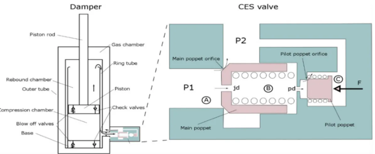
A sketch of the damper is seen in Figure 3. The damper consists of an outer cylindrical tube with two cylindrical tubes inside. The two tubes on the inside form a ring tube for the oil to flow in. In the piston as well as in the base, there is a check valve that makes sure that the oil will flow in only one direction through the CES valve. There is also a blow-off valve in the piston and in the base that prevents a too high pressure build up. The CES valve enables a certain amount of control over the damper characteristics. In a conventional damper, used in most cars, oil is forced through a fixed orifice or spring loaded check valve which creates damping. In the suspension system containing the CES valve on the other hand, the damping orifice is electronically controlled by the car control unit. When the damper is compressed or in rebound the oil is forced to flow through the CES valve. The valve is working as a controllable restriction which creates a pressure drop between the two damper chambers.
A principle sketch of the CES valve is shown in Figure 3 and a cross section drawing of the valve is shown in Figure 4. A brief explanation of the function follows: Assume that a pressure P1 is created due to damper motion. A pressure will then also be created inside the main poppet due to the jd restriction (B). As long as the pilot poppet is closed there will be no flow through the jd or pd restriction and therefore the pressure inside the main poppet (B) will be P1. The closing force will now be the spring force plus the pressure inside the main poppet acting on the inner main poppet area resulting in a closed valve. For the main poppet to open, the volume inside the poppet (B) needs to be evacuated. When the force created by P2 (C) together with the pilot poppet spring and the force F is smaller than the force created by P1 (on the pilot poppet) the pilot poppet will open. When this occurs the pressure inside the main poppet (B) decreases, the volume inside can be evacuated through the pilot orifice and the main poppet can open. The largest portion of the oil will then flow through the main poppet orifice. A smaller portion will flow through the jd restriction, on through the pd restriction and through the pilot orifice according to the arrows in Figure 3. By using this concept the dimensions can be made smaller than on a single stage pressure regulator since the pressures that is controlled is also amplifying the pressure regulator force. It also means that the closing force of the pressure regulator will be dependent on the
pressures P1 and P2. By controlling the force F with help of an electro magnet, the valve becomes continuously controlled. The valve can be configured to over 100 variants by switching some of the components. This enables many different valve characteristics.
Figure 3. A principle sketch of the damper (left) and CES valve (right) 4.3 Simulations during technology development
The case company has throughout the years had issues with the internal damping in the valve. This is not to be confused with the damping that is created by the damper and the valve together. The internal damping refers to how the main and pilot poppet inside the valve are damped i.e. what velocity dependent forces that are active on the components. The valve is exposed mainly to two different kinds of situations when used in a damper: (1) The car hits a road bump which creates an increase of pressure in the damper. This forces the main and pilot poppet to open more, hence they need to move and find a new position which will create a short pressure spike in the damper. (2) The second case is when the car control unit for some reason regulates the valve by changing the solenoid force on the pilot poppet. The damping in both cases will refer to the time needed for the main and pilot poppet to reach their final positions and the effect on the controlled pressure in the damper which is directly affecting the driver comfort. There are two tests that are used to simulate these situations in a test bench: Passive Step Response (PSR) refers to situation 1. In this case the solenoid force is kept constant and then a sudden flow spike is forced through the valve. Active Step Response (ASR) refers to situation 2 and an example of the simulation signal can be seen in Figure 4. In this test the flow is kept constant on 3 levels and then the solenoid force is changed in order to change the controlled pressure.
Figure 4. A cross section drawing of the CES valve (left) and the signal used for ASR simulation (right)
The illustrative example focuses on the development phase where new technologies needs to be brought to the table in order to increase the performance of the CES valve. Several solutions were created and
simulated during the study. However, the section will focus on one technology concept to be able to describe it in detail.
In order for a technology to be successful it needs to improve the valve to perform better than the original in both ASR and PSR simulations and testing. For this reason the test conditions for ASR and PSR was set up in the software simulation package LMS AMEsim which is a 1 dimensional simulation tool with a hydraulic package. This software was already in use in the company and the CES valve, currently in production, was already modelled and validated. A simple 3-stage process was applied during TD in order to generate and to a certain level evaluate new technologies. This process can be seen in Figure 5. The steps is further explained and applied to one of the technology concepts bellow:
Figure 5. The simple 3 stage process applied in TD
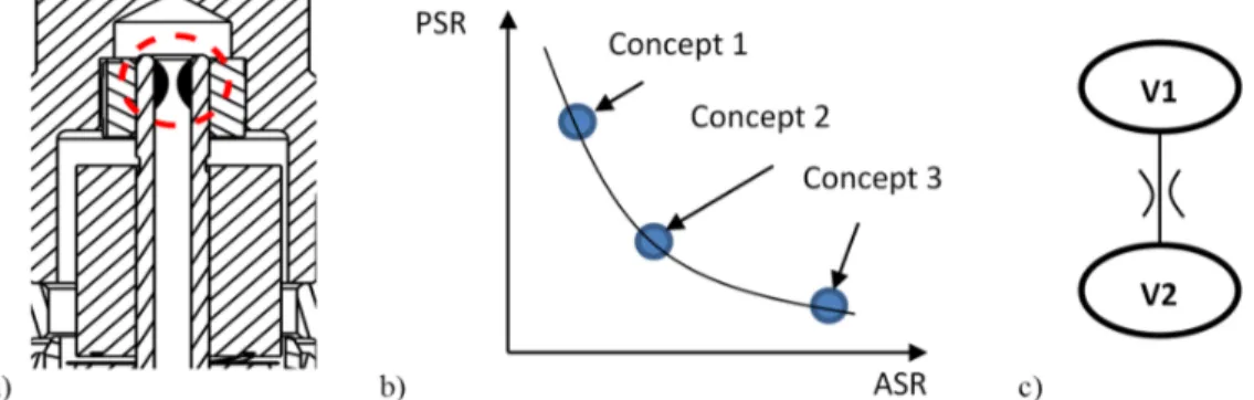
The first part contains idea generation and sketching and was performed using 2D drawings of the CES valve. This was due to that the aim was not to invent a new CES valve from scratch but to improve the current design by making small conceptual changes. Figure 6.a shows one of the generated concepts and the sketch that was produced. The idea introduced an orifice in the solenoid rod in order to introduce damping of the pilot poppet. The damping arises due to forcing the oil through the introduced orifice when the pilot poppet moves. This creates a counteracting force acting on the solenoid rod.
During the second step the concepts are analysed in order to decide if it is possible to use 1D simulation for modelling. The concept was then modelled on top of the validated model of the CES valve. The simulations are then iterated to find suitable parameter values. The software then allows for plotting of any variable against another after the simulation has been run. The simulation result are then used to plot trade-off curves showing how the concepts perform in the different simulated tests. An example of such a trade-off curve is shown in Figure 6.b In the figure it can be seen that improving the valve behaviour in the ASR simulation often results in reduced performance in PSR simulations.
As seen in Figure 6.c, the concept could be modelled using an orifice block in the simulation software that uses the orifice equation seen in Equation 1, where q is the flow, Cq is the flow coefficient, A is the orifice area, ρ is the density of the fluid and Δp is the pressure difference. The simplified hydraulic scheme is conceptual and only describe the introduced orifice and the adjacent volumes. Since the valve can be configured to several variants, bandwidths were defined for those parameters. Due to limitations in time and computer power not all of the variants could be simulated in this stage. A number of configurations were picked that spanned the design space of the CES valve.
Figure 6. a) Sketch of the concept, b) Trade-off comparing three concepts, c) Hydraulic scheme of the simulation model
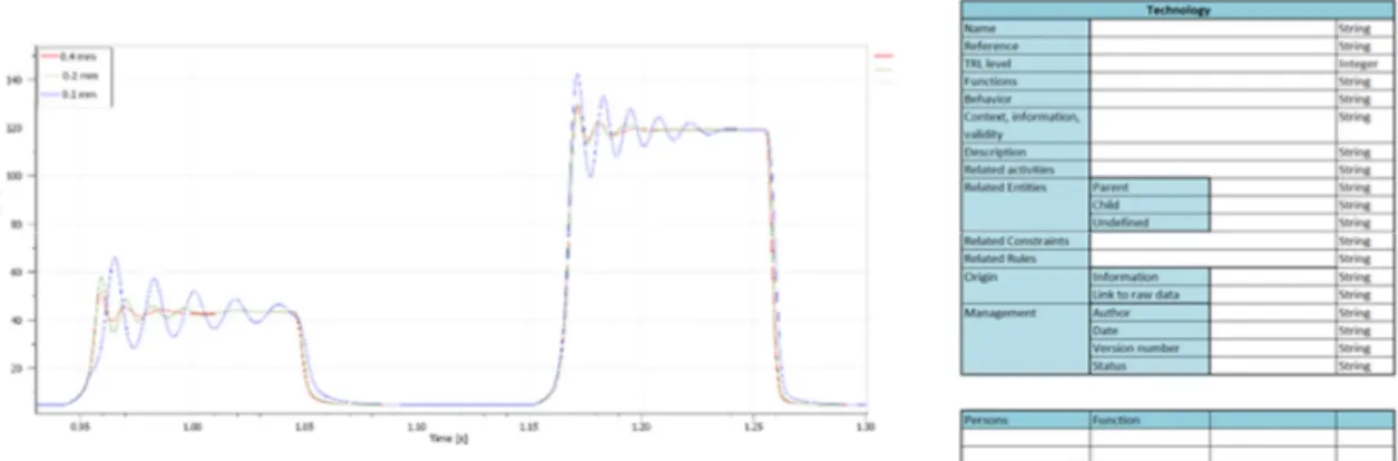
(1) In step 3 these simulation files are saved together with simulation data which makes access to the data simple. The principles of each concept is then described using a form visible in Figure 7 (right). The form is the realization of the Technology Description and is filled in with descriptions regarding TRL, function, behaviour, images, links to relevant files, raw data etc. In this way the concept is stored, described and made available for the subsequent PD. When a new PD project is initiated these concepts can be scanned and picked from the platform as a base for further exploration. The suitability can then be evaluated before going into the design stage. An example of an ASR step response simulation is shown in Figure 7 (left). The figure shows the different dynamic behaviour when changing the size of the introduced orifice.
Figure 7. The concept model behaviour in an ASR step response simulation with different orifice size (left) and the technology description form (right)
5. A platform model to support the interface between technology- and product
development for suppliers of highly advanced and customized systems
The traditional way to use a platform approach is to preplan variants and to design a configurable component based platform that in some way consist of assemblies and parts. This assumes that future requirements and interfaces on the product are known or estimated. This would however increase the risk of losing projects to another supplier that agrees to a higher level of customization due to that the predeveloped variants does not comply with the customer requirements. The platform approach presented here is instead about realizing that changes will occur and to use the platform description to generate solutions, which could be a finished design, but also supports knowledge description on a higher level of abstraction that potentially makes the area of application larger. The introduction of this continuous evolving platform that encapsulates different descriptions and carriers of information and knowledge requires the definition of solutions as design spaces, the generalization of product items, the assessment of trade-offs and the formalization of engineering processes.
This paper proposes that the common structure that creates the platform can partially be made up by technology concepts on different levels of realisation that upon request can be drawn from the platform and introduced in one or several subsequent PD projects. In this way another important company asset, the core technology, can be reused. This paper's contribution lies in this context and elaborates on how simulations of novel technologies can be a part of constituting this platform and in turn support the interface between TD and PD. The focus of the illustrative case is upon describing estimations of the dynamic behaviour of a novel technology even before any 3D geometry have been designed. When a technology has reached a certain level of maturity it can be saved using the proposed format Technology Description and thus be part of the platform. The description of the technology can then be picked from the platform and create a base for developing or improving a product. It is important that the outcome from TD is described in a formalized manner in order to create a coherent platform. Further, the
p A C q q
2descriptions must be done in such a way that the technologies ability to adapt can be judged by the design engineers using the technology.
A few limitations of the case can be mentioned. The dynamics of hydraulic systems are specifically suitable for 1D simulations since the equations describing the behaviour can be evaluated on a simple level. This results in that the process proposed in the case cannot be applied to all TD and PD projects. The suitability also depends on the type of technology being developed. The 1D simulations are also limited to what design changes that can be modelled during TD. When it comes to more advance geometrical inventions in order to e.g. affect turbulence in the valve, Computational Fluid Dynamics (CFD) or Fluid Structure Interaction (FSI) are more suitable. This however puts more requirements on how far into the design stage the solutions needs to be brought.
Figure 8. The visualisation of the case outcome in the platform model
6. Conclusions and future work
This paper proposes a high level platform approach in order for companies to describe, preserve and reuse more of the knowledge created during TD and PD. A case is presented describing an instance of what the proposed platform model can contain. The case elaborates on the simulation of technology concepts in early phases of TD before any 3D geometry has been designed. A simple process is proposed describing three steps that aims to make some early predictions of generated concepts as well as describing them for the subsequent PD. A great strength of doing these early simulations is that the technical principle can be investigated, and to a certain extent, evaluated before going in to the design stage. The approach is also supported by a Set-Based Concurrent Engineering working approach by early on defining design spaces and working with several concepts in parallel. By introducing new ways of describing the created knowledge in a standardized format, thus making it part of a coherent platform, the technology transfer step is supported. The descriptions of the simulated technology concepts is what in this paper enables the use of the common structure that can form the base in several products and in turn extends the presented platform model.
The future work consist of refining the way the technology concepts are described as well as following the path of PD when they are to be used. For the platform approach, more examples are to be investigated. The format of what connects all these different descriptions that the platform model can contain are also to be refined.
Acknowledgements
This work would not have been possible without the aid of supervisors and the case company. The author would like to thank the case company for invaluable information and recourses.
References
André, S., Stolt, R., Elgh, F., "Introducing Design Descriptions on Different Levels of Concretisation in a Platform Definition", Paper presented at the PLM International Conference, 2015.
André, S., Stolt, R., Elgh, F., Johansson, J., Poorkiany, M., "Managing Fluctuating Requirements by Platforms Defined in the Interface Between Technology and Product Development", Paper presented at the Advances in Transdisciplinary Engineering: Moving Integrated Product Development to Service Clouds in the Global Economy, Amsterdam, 2014, pp. 424-433.
Claesson, A., Rosvall, B. r., Johannesson, H., "Capturing design knowledge of robust designs using configurable components", Paper presented at the ASME 2005 International Design Engineering Technical Conferences and Computers and Information in Engineering Conference, 2005, pp. 423-434.
Clausing, D., "Total Quality Development: A step-by-step guide to world-class concurrent engineering", American Society of Mechanical Engineers, Cambridge Massachusetts, 1996.
Cooper, R. G., "Managing technology development projects", Research Technology Management, Nov/Dec, 2006, pp. 23-31.
Corin Stig, D., "Technology Platforms: Organizing and Assessing Technological Knowledge to Support its Reuse in New Applications", Chalmers University of Technology, 2015.
Eldred, E. W., McGrath, M. E., "Commercializing new technology-II", Research Technology Management, Vol.40, No.2, 1997, p. 29.
Ericsson, A., Erixon, G., "Controlling design variants: modular product platforms", Society of Manufacturing Engineers, 1999.
Halman, J. I. M., Hofer, A. P., Vuuren, W. V., "Platform-driven development of product families - Linking theory with practice", Journal of Product Innovation Management, Vol.20, No.2, 2003, pp. 149-162.
Högman, U., "Processes and Platforms Aligned with Technology Development - The perspective of a supplier in the Aerospace Industry", Göteborg: Chalmers tekniska högskola, 2011.
Hvam, L., Mortensen, N. H., Riis, J., "Product customization", Springer Publishing Company, 2008.
Johansson, J., André, S., Elgh, F., "Simulation Ready CAD-Models as a Means for Knowledge Transfer Between Technology Development and Product Development", Paper presented at the DS 80-6 Proceedings of the 20th International Conference on Engineering Design (ICED 15), Vol.6: Design Methods and Tools-Part 2, 27-30.07., Milan, Italy, 2015.
Lakemond, N., Johansson, G., Magnusson, T., Säfsten, K., "Interface between technology development, product development and production - Critical factors and a conceptual model", International Journal of Technology Intelligence and Planning, Vol.3, No.4, 2007, pp. 317-330.
Levandowski, C., Raudberget, D., Johannesson, H., "Set-Based Concurrent Engineering for Early Phases in Platform Development", Paper presented at the The 21st ISPE International Conference on Concurrent Engineering-CE2014, 2014.
Levandowski, C., Stig, D. C., Raudberget, D., Johannesson, H., "Accommodating Emerging Technologies in Existing Product Platforms", Paper presented at the 24th International Association for Management of Technology Conference (IAMOT 2015), 2015, pp. 2237-2252.
Mankins, J. C., "Technology readiness levels", White Paper, April, 6, 1995.
Meyer, M. H., Lehnerd, A. P., "The power of product platforms - Building value and cost leadership", New York, The Free Press, 1997.
Nobelius, D., "Linking product development to applied research: transfer experiences from an automotive company", Technovation, Vol.24, No.4, 2004, pp. 321-334.
Nobelius, D., "Managing R&D Processes - Focusing on Technology Development, Product Development and their Interplay", Göteborg, Chalmers University of Technology, 2002.
Raudberget, D., "Industrial Experiences of Set-Based Engineering - Effects, results and applications", Göteborg, Chalmers reproservice, 2012.
Ravn, P. M., Gudlaugsson, T. V., Mortensen, N. H., "A multi-layered approach to product architecture modeling: Applied to technology prototypes", Concurrent Engineering, 2015.
Robertson, D., Ulrich, K., "Planning for product platform", Sloan Management Review, 1998, pp. 19-31. Säfsten, K., Johansson, G., Lakemond, N., Magnusson, T., "Interface challenges and managerial issues in the industrial innovation process", Journal of Manufacturing Technology Management, Vol.25, No.2, 2014.
Simpson, T. W., Siddique, Z., Jiao, J., "Product platform and product family design - Methods and application", New York, Springer science+Business media Inc., 2006.
Samuel Erik André, M.Sc
Jönköping University, Department of Product Development Drivhusvägen 38, 56139 Huskvarna, Sweden
![Figure 1. The technology transfer process - adopted from [Eldred et al. 1997]](https://thumb-eu.123doks.com/thumbv2/5dokorg/4563993.116564/2.918.304.617.95.280/figure-technology-transfer-process-adopted-eldred-et-al.webp)