ADVANCED POWER THEORIES AND SIGNAL DECOMPOSITION
METHODS FOR CONTROLLING SMART CONVERTERS
IN SMART GRID APPLICATIONS
by: Farnaz Harirchi
© Copyright by Farnaz Harirchi, 2017 All Rights Reserved
ii
A thesis submitted to the Faculty and the Board of Trustees of the Colorado School of Mines in partial fulfillment of the requirements for the degree of Doctor of Philosophy (Electrical Engineering). Golden, Colorado Date ____________________ Signed: _________________________ Farnaz Harirchi Signed: _________________________ Marcelo G. SimÕes Thesis Advisor Signed: _________________________ Ahmed Al Durra Thesis Co-Advisor Golden, Colorado Date _____________________ Signed: _________________________ Prof. Atef Z. Elsherbeni Professor and Head Department of Electrical Engineering
iii
ABSTRACT
During last two decades, the enormous level of aggregation of distributed generation units DGUs (widely known as the technology of Microgrids), in addition to increasing usage of nonlinear loads in power systems has raised new mathematical-conceptual challenges, specially in power electronics. Most of the traditional power theories and concepts therein, have been defined and formulated for simple balanced and linear systems. As a result, most of them are not directly applicable in case of new system structures with a considerable amount of uncertainty in the production and nonlinearity in the consumption. Due to uncertainties injected by the dynamic behavior of the DGUs (mostly renewable-based), the power components in the traditional power theories should be redefined under highly dynamic behavior of the power signals. Moreover, corresponding justifications need to be implemented to adapt all the related control strategies and compensation techniques. Renewable-based energies, such as wind and solar, are inherently uncertain power sources which can have unpredictable unwanted impacts on power flow, voltage regulation, and result in distribution losses. Microgrids that are quickly expanded through the power networks and power theories play a critical role in all the control strategies designed for these systems. When operating in the islanded mode, low-voltage Microgrids can exhibit considerable variation of amplitude and frequency of the voltage supplied to the loads, thus affecting power quality and network stability. Limited power capability in Microgrids can cause a voltage distortion which affects measurement accuracy, and possibly cause tripping of protections. Besides, the nonlinear and unbalanced loads obscure the traditional power definitions and equations. In such contexts, a reconsideration of power theories is required, since they form the basis for supply and load characterization and accountability. Moreover, developing new control techniques for harmonic and reactive compensators are mandatory, because they operate in a strongly interconnected environment and must perform cooperatively to face system dynamics, ensure power quality, and limit distribution losses.
The main purpose of this research is to improve the quality, reliability and stability of future electrical power delivery by improving the overall performance of smart Microgrids through usage of advanced time-domain power theories (such as instantaneous power theory (PQ) and Conservative Power Theory (CPT)). Another major contribution of this work is the introduction
iv
of new mathematical power theory concepts (termed Enhanced Instantaneous Power Theory (EIPT)) in addition to implementation of adequate new control strategies. This work specially expanded based on a specific viewpoint which says that power theories can be interpreted as advanced signal decomposition techniques which are used as the initial step in electrical power signals analysis. This signal analysis step forms the fundamental headstock for power electronic interfaces controller design procedure. After describing the mathematical fundamentals of our modified power theory, EIPT; then this method is used as a time-domain signal decomposition approach for relevant applications. Exploiting the fine levels of information revealed through analysis of the power signals with the mentioned decomposition approaches, we provide more levels of freedom in the case of control frameworks. This research also investigate the interesting application of EIPT, besides other practical power theories such as CPT, in islanding detection problems, where a new instantaneous intelligent passive islanding detection strategy will be introduced. In a nutshell, developing new time-domain power theory concepts while exploiting the inherent capacities of the pre-existing power theories, the main goal of this work will be designing a reliable and smart multifunctional control scheme that can address all the aforementioned challenges.
v
TABLE OF CONTENTS
ABSTRACT ... iii
LIST OF FIGURES ... viii
LIST OF TABLES ... xii
NOMENCLATURE AND ABBREVIATIONS ... xiii
ACKNOWLEDGMENTS ...xv
DEDICATION ... xvi
CHAPTER 1 INTRODUCTION ...1
1.1 Distributed Generation, Renewable Energy and Microgrids: Role of Power Electronics ...1
1.2 Microgrid: A Challenging Double Mode System ...2
1.3 Overview and Contributions ...4
CHAPTER 2 POWER THEORIES AND ELECTRICAL POWER SIGNAL DECOMPOSITION TECHNIQUES ...7
2.1 Fundamental Concepts and Definitions ...7
2.2 Different Categories of Power Theories ...9
2.2.1 Frequency Domain ...9
2.2.2 Time Domain ...9
2.2.3 Time-Frequency Domain ...10
2.3 Definition of Power Components Within the Most Famous Time Domain Power Theories Under Unbalanced and Nonlinear Condition ...10
2.3.1 Instantaneous Power Theory (PQ Theory) ...10
2.3.2 The FBD Theory ...13
2.3.3 Synchronous Reference Frame Method (��) ...15
2.3.4 Generalized Instantaneous Power Theory ...17
2.3.5 Conservative Power Theory (CPT) ...18
2.4 Discussions ...22
CHAPTER 3 ENHANCED INSTANTANEOUS POWER THEORY ...25
3.1 Overview ...25
3.2 Enhanced Instantaneous Power Theory and Current Decomposition Methodology ...26
vi
3.3 Mathematical Methodology For Current Decomposition In Three-Phase
Nonsinusoidal Unbalanced System With Symmetrical Balanced Voltage Source ...28
3.3.1 Fundamental Definitions ...28
3.3.2 EIPT Current Decomposition Approach: Concepts and Components ...31
3.4 Mathematical Methodology for Current Decomposition in Three-phase Nonsinusoidal Unbalanced System with Asymmetrical Unbalanced Voltage Source ...35
3.4.1 A Note on the Source of Unbalance ...36
3.5 An alternative approach for current decomposition in three-phase non-sinusoidal unbalanced system with unbalanced and distorted voltage source ...41
3.6 Orthogonality of Components ...43
3.7 Case Studies and Discussions ...44
CHAPTER 4 INTELLIGENT INSTANTANEOUS ISLANDING DETECTION IN SMART GRID ...55
4.1 Introduction and Overview ...55
4.2 State of the art in the literature in the passive islanding detection ...57
4.3 Technical Challenges and Contributions ...58
4.4 Islanding (Fault) Scenarios ...60
4.5 Instantaneous 3-phase Fault-Oriented Islanding Detection and Classification ...60
4.6 3-phase Feature Extractors: DQ, CPT and EIPT ...63
4.7 IIPID Feature Spaces ...83
4.7.1 IIPID Feature Spaces: DQ, CPT, and EIPT-based spaces ...84
4.7.2 IIPID Feature Spaces: Dynamic-Static features ...86
4.8 IIPID Classification Using Multilayer Perceptron Neural Network ...88
4.8.1 Network Architecture ...89
4.8.2 Training-Test Data and the Learning Back-propagation Algorithm ...91
4.9 Experimental work: Protection system for Grid-connected inverter using instantaneous islanding detection method ...94
4.9.1 Master and Slave Circuit Breakers ...95
4.9.2 Push Buttons ...95
4.9.3 Relay Control Board ...95
4.9.4 Protection Board ...97
vii
CHAPTER 5 ADVANCED CONTROLLERS DESIGN FOR MULTIFUNCTIONAL
SMART MICROGRIDS ...101
5.1 Overview ...101
5.2 Analysis of FIBC and FIBBC ...102
5.2.1 Analysis of FIBBC ...102
5.2.2 Controller Design ...106
5.3 Multifunctional Double Mode Inverter (MFDMI) ...108
5.3.1 Operational Modes for MFDMI ...108
5.3.2 Proposed Control Scheme ...109
5.3.3 Simulation Results ...117
CHAPTER 6 CONCLUSION AND FUTURE RESEARCH ...125
6.1 Conclusions ...125
6.2 Future Directions ...128
REFERENCES CITED ...130
viii
LIST OF FIGURES
Figure 2.1 The history chart of the power theories ...8
Figure 2.2 Algorithm to find harmonic components for harmonic compensation by using p-q theory ...13
Figure 2.3 �� method for current decomposition ...16
Figure 2.4 Resistive load with periodic switch ...21
Figure 3.1 Three-phase power system results of the CIC-PQ (Confusion Matrix) ...26
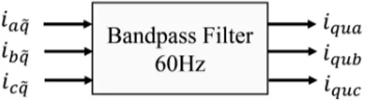
Figure 3.2 Bandpass filter used for extraction of unbalanced active currents ...33
Figure 3.3 Bandpass filter used for extraction of unbalanced reactive currents ...35
Figure 3.4 Bandpass filter used for extraction of unbalanced active currents ...39
Figure 3.5 Bandpass filter used for extraction of unbalanced reactive currents ...40
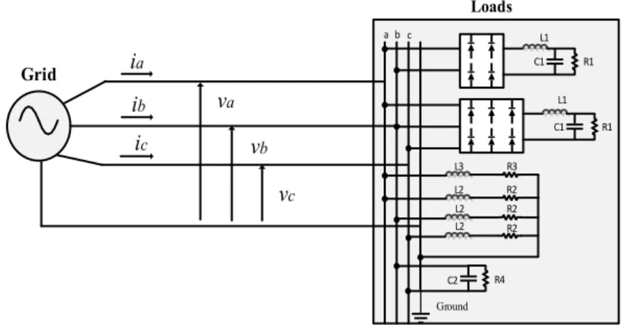
Figure 3.6 Three-phase four wire system with different types of loads ...44
Figure 3.7 Decomposed current components, in case of balanced linear load ...45
Figure 3.8 Decomposed current components in phases �, � and � in case of balanced non-linear load ...46
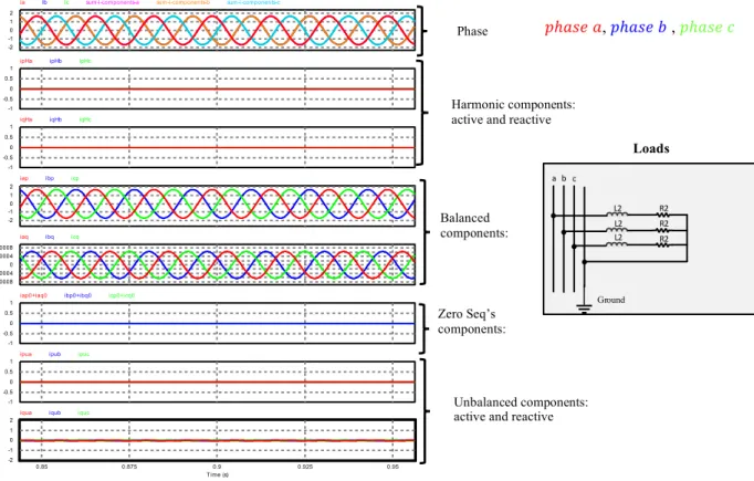
Figure 3.9 Decomposed current components in phases �, � and � in case of unbalanced linear load . ...47
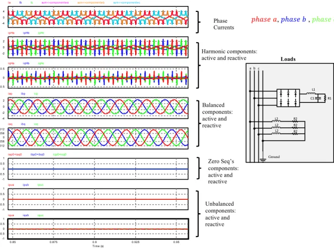
Figure 3.10 Decomposed current components in case of unbalanced non-linear load. ...48
Figure 3.11 Reactive powers in different phases and their aggregation in case of unbalanced non-linear load ...48
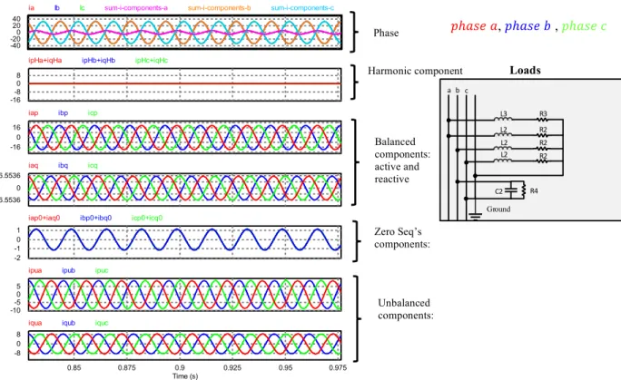
Figure 3.12 Decomposed current components in case of unbalanced non-linear load and unbalanced asymmetrical voltage source ...49
Figure 3.13 Reactive powers in different phases and their aggregation in case of unbalanced non-linear load and unbalanced asymmetrical voltage source ...50
ix
Figure 3.15 Active and reactive current components in EIPT and CPT ...51
Figure 3.16 Harmonic and unbalance current components in EIPT and CPT ...51
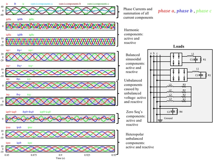
Figure 3.17 Heteropolar, homopolar and the total unbalance current components in the EIPT. .52 Figure 3.18 Current waveforms of the load in phases a, b and c ...53
Figure 3.19 Active and reactive current components in EIPT and CPT ...53
Figure 3.20 Harmonic and unbalance current components in EIPT and CPT ...54
Figure 3.21 Heteropolar and homopolar and total (heteropolar+homopolar) unbalance current components in EIPT. ...54
Figure 4.1 The general scheme of IPID approach. ...59
Figure 4.2 The temporal behavior of the 3-phase voltage signal under each 10 different 3-phase fault scenarios. ...61
Figure 4.3 Temporal behavior 3-phase Voltage in time window. ...65
Figure 4.4 Harmonic components of EIPT in different faults. ...67
Figure 4.5 Unbalanced component of EIPT in different faults. ...69
Figure 4.6 Pure sinusoidal component of EIPT in different faults. ...71
Figure 4.7 Harmonic component of CPT in different faults. ...73
Figure 4.8 Unbalanced component of CPT in different faults. ...75
Figure 4.9 Pure sinusoidal component of CPT in different faults. ...77
Figure 4.10 �� in different faults. ...79
Figure 4.11 �� in different faults. ...81
Figure 4.12 1-D feature space of IIPID (histogram of the ����) ...83
Figure 4.13 a) Corresponding 3D IIPID problem feature space formed out of 3 EIPT-based extracted features. b) Corresponding 3D IIPID problem feature space formed out of CPT-based extracted features. c). Corresponding 2D IIPID problem feature space formed out of 2 DQ-based extracted features. ...85
x
Figure 4.14 a) Corresponding 2D IIPID problem feature space formed out of � − ���������� and �����∅ as features. b) Corresponding 2D IIPID problem feature space formed
out of � − ��������� and �����∅ as features. ...87
Figure 4.15 3D dynamic-static feature space using EIPT and CPT theories ...88
Figure 4.16 A linear vs a non-linear class boundary in the IIPID feature space for Each PQ Class ...89
Figure 4.17 The architecture of the implemented neural networks ...90
Figure 4.18 The schematic of the experimental set up ...94
Figure 4.19 Master and slave circuit breakers ...95
Figure 4.20 Inputs and outputs of the relay control board ...96
Figure 4.21 Relay control board ...96
Figure 4.22 Protection board ...97
Figure 4.23 Dynamic Breaker ...98
Figure 4.24 Power supply for dynamic breaker ...98
Figure 4.25 Comparison circuit of the DB ...99
Figure 4.26 Optocoupler used as an interface for DB system ...99
Figure 4.27 Power dissipating part for DB system ...99
Figure 4.28 Implemented DB circuit ...100
Figure 5.1 Schematic of the grid connected PV system with all power electronic interfaces ..101
Figure 5.2 Schematic of the FIBBC ...102
Figure 5.3 Bode diagram of the FIBBC in Boost mode ...105
Figure 5.4 Bode diagram of the FIBBC in Buck mode ...105
Figure 5.5 Bode diagram in Buck mode for FIBBC with and without controller ...107
xi
Figure 5.7 SRF PLL implementation ...110
Figure 5.8 Current control diagram in the GT mode ...113
Figure 5.9 Schematic of PIR controller ...114
Figure 5.10 Voltage control diagram in the islanded mode ...115
Figure 5.11 Unified Control algorithm for MFDMI with a smooth transition between two main operational modes ...116
Figure 5.12 a) Current of nonlinear load b) Compensating current calculated by EIPT c) Compensated grid current after adding nonlinear load at 0.1, and removing nonlinear load at 0.3s ...118
Figure 5.13 Implemented a) PCC voltage after inverter goes to the islanded mode from the GT mode at 0.4s. b) PCC voltage after inverter goes from the islanded mode to the GT mode at 0.6s DB circuit ...118
Figure 5.14 Injected current to grid in different operational conditions of MFDMI ...119
Figure 5.15 a) Comparison between �6 and �6789 and, b) Comparison between �: and �:789 ...119
Figure 5.16 Voltage and injected currents (��) to the grid at PCC a) without compensation, b) with harmonic compensation, c) with imbalance compensation, and d) with full compensation ...120
Figure 5.17 The real-time simulation realization using OPAL-RT-32 port OP5312 ...122
Figure 5.18 Voltage and injected current (��) at the PCC after changing control method from a) GT to islanded, b) islanded to GT mode ...122
Figure 5.19 Output (��) a) active and b) reactive powers at PCC vs their ref value ...123
Figure 5.20 Voltage and current waveforms of the source in phases a, b and c. ...123
Figure 5.21 active and reactive current components in EIPT ...124
Figure 5.22 harmonic and unbalance current components in EIPT ...124
Figure 5.23 Grid currents after compensation (a) using EIPT (b) using CPT ...124
xii
LIST OF TABLES
Table 2.1 Properties of the most famous power theories ...23
Table 2.2 Current components compared in power theories ...23
Table 2.3 Power Terms in different power theories ...24
Table 5.1 Parameters of the FIBBC ...106
Table 5.2 Parameters of the Type-III Compensator ...107
xiii
NOMENCULATURE AND ABBREVIATIONS
�>?@: instantaneous voltage vector in the ��� frame
�>?@ : instantaneous current vector in the ��� frame �FGH: ��0 transformation matrix
�FGH: instantaneous voltage vector in the ��0 frame
�FGH : instantaneous current vector in the ��0 frame
� : active power � : reactive power
� : instantaneous active power � : instantaneous reactive power
�>, �? and �@: instantaneous active power in phase �, � and � respectively �>, �? and �@: instantaneous reactive power in phase �, � and � respectively �FG: instantaneous active heteropolar power component
�RG: average active balanced heteropolar power component
�FG: oscillating active heteropolar power component
�H: instantaneous active unbalanced homopolar power component
�FG: instantaneous reactive heteropolar power component �FG: average reactive balanced heteropolar power component �FG: oscillating reactive heteropolar power component
�FH and �GH: instantaneous unbalanced homopolar reactive power component �S: instantaneous active current
�:: instantaneous reactive current
�>ST, �?ST, �@ST: active unbalanced homopolar current components in phase �, � and � respectively
�>S, �?S and �@S: active balanced sinusoidal current components in phase �, � and � respectively �>S, �?S and �@S: active oscillating current components in phase �, � and � respectively
iSV>, �SV?, �SV@: active unbalanced heteropolar current components in phase �, � and � respectively �SW>, �SW? and �SW@: active harmonic current components in phase �, � and �, respectively
xiv
�>:T, �?:T, �@:T: reactive unbalanced homopolar current components in phase �, � and � �>:, �?:, �@:: reactive balanced sinusoidal current components in phase �, � and � respectively �>:, �?:, �@:: reactive current components in phase �, � and � respectively
i:V>, �:V?, �:V@: reactive unbalanced heteropolar current components in phase �, � and �
�:W>, �:W? and �:W@: reactive harmonic current components in phase �, � and �, respectively
�SV>X, �SV?X, �SV@X:active unbalanced part of current components caused by unbalanced part of voltage source in phase �, � and �
�:V>X, �:V?X, �:V@X:reactive unbalanced part of current components caused by unbalanced part of voltage source in phase �, �and �
�SW>X, �SW?X, �SW@X: active harmonic part of current components caused by distorted part of voltage source in phase �, � and �
�:W>X, �:W?X, �:W@X: reactive harmonic part of current components caused by distorted part of voltage source in phase �, � and �
xv
ACKNOWLEDGMENTS
The research in this thesis would have taken far longer to complete without the encouragement from many others. It is a delight to acknowledge those who have supported me over the last four years. I give my first thanks to God for protection and ability to work during my Ph.D program. Success and final outcome of this project required a lot of guidance, assistance and support from my thesis advisor Prof. Marcelo Godoy SimÕes and I am extremely privileged to have got this all along the completion of my project. I owe my deep gratitude to him because of the exceptional opportunity he provided for me and my husband to work together during our PhD program in Colorado School of Mines. A famous scientist, a great advisor and a truly affectionate father for his students. I heartily thank you and your lovely wife Debora for your patience, motivation, immense knowledge and all your kindness.
Nevertheless, I am also grateful to our colleagues from PI, Dr. Ahmed Al Durra and Dr. S.M Muyeen, for the continuous support of my Ph.D. study and related research. I am particularly thankful for the help and advice of Dr. Enio Riberio, Dr. Salman Mohagheghi, and Dr. Raveal Ammerman that helped me in all the time of research and completion of this PhD thesis. Besides, I sincerely appreciate the chair of my thesis committee, Dr. John Steele for his time and support within this project. I would also like to express my sincere gratitude to Dr. Elsherbeni for his continuous support of my Ph.D program in the EE department of the CSM.
I was very lucky to have my brother, Farshad and his lovely wife, Yasaman, just beside during these years. Their presence gives me hope and energy, thanks for your supports. I am the luckiest person because of having the best parents in law, Mahroo and Khosro. Thanks for your endless love.
The days would have passed far more slowly without the support of my friends (Mahmoud, Elham, Neema, Azita, Naser, Shirin, Hossein, Bananeh…) without whom this period of my life could not be this much memorable. The gatherings, hiking and camping among many other funs we had, cannot be forgotten for my whole life. Last but not the least, I would like to thank my fellow colleagues for their feedback, cooperation and of course friendship: Hossein, Bananeh, Sepideh, Abdullah, Xuliang, Moein, Ricardo, Abdulhakeem, Ali, Varaprasad, and Falah.
xvi
This is dedicated
To my grandfather Javad Harirchi
You showed me the right path for success with your lessons and encouragements. Your soul may rest in peace.
To the best parents in the world Shadi and Farhad
The reason of what I become today. During all these years I missed you every second but you always gave me a positive energy. Your boundless love and continuous care helps me through all the challenges and difficulties in life.
I cannot imagine the life without you.
To my beloved companion, Mohammad
Thanks for your patience, endless love and support during the past four years. Every single day I spend as your wife I realized how lucky I am to live such an amazing life.
I love you to moon and back.
1
CHAPTER 1
INTRODUCTION
In this chapter, an overview on the Microgrids technology, opportunities and challenges, in addition to the motivation for and contributions of this work is presented.
1.1 Distributed Generation, Renewable Energy and Microgrids: Role of Power Electronics Nowadays rising global electrical energy consumption is a big challenge in the electrical power delivery system. As a solution to this increasing ramp up in demand, the traditional power systems are changing globally, and many distributed generation (DG) units1, including both renewable and nonrenewable energy sources such as wind turbines, photovoltaic (PV) generators, fuel cells, combined heat and power stations, are being integrated into power systems at the distribution level. Microgrids, also named minigrids, are becoming an important concept for integrating distributed generation and distributed storage systems. This concept has been developed to cope with the penetration of renewable energy systems, which can be realistic if the final user is able to generate, store, control, and manage part of the energy that will be consumed. Microgrids should be able to locally solve energy problems and hence increase flexibility. Based on the connection situation of the Microgrid with the main grid, there are two modes of operation for Microgrids, the “Grid Connected2 (GC)” mode and “Islanded Mode” (Stand-Alone Mode). The use of distributed generation (DG) makes no sense without using distributed storage (DS) systems to cope with the energy balances.
Power electronics, the technology of efficiently processing electric power, plays an essential role in the integration of the distributed generation units to develop efficient and high-performance power systems. Different power electronic topologies are designed for each of the DG systems; however, in all types of DG or Microgrid configurations, power electronic converters play an important role to control the flow of power and convert it into a suitable DC or AC form as
1
In many contexts, the terms Microgrid and DGU have been used interchangeably, although, usually a Microgrid includes one or more number of DGUs.
2 In the rest of this document, we may use the following two terms interchangeably: grid connected (GC) and
2
required. These converters can be intelligently designed to support a variety of fundamental functionalities which are needed to be implemented in Microgrids. The most important functionalities of control frameworks in Microgrids are mentioned below.
1.2 Microgrid: A Challenging Double Mode System
Several studies are considering Microgrids with single operational mode inverters (which can operate only in the GC [1] or only in the islanded situation [2]). However, in practice, the double-mode Microgrids are widely preferred. Another important required functionality for future smart Microgrids is grid supporting. Regarding new industrial standards, future smart Microgrids should be able to negotiate with the main grid. Specifically, they must be equipped with the capability of injecting active and reactive power to the main grid (during load peak hours) to retain the adequate frequency and stabilize the voltage magnitude. Due to different objectives in each operating mode (current control in the GC mode and voltage control in the islanded mode), the inverter’s control framework will be more complicated in double-mode Microgrids. Consequently, another desirable feature of a double-mode smart inverter is a smooth transition between the islanded and GC modes [3]. As an instance, in [3], a master-slave based control system is used to provide a smooth transition between two modes; however, because of using two distinct controllers and switching between these two controllers, the transient response is still considerable. As a result, an adequate smart Microgrid system should be equipped with fast but reliable transition methods that can quickly detect the failures of the main grid and switches between two operating modes.
Another important concern regarding aggregation of Microgrids (which is more highlighted in the case of renewable based distributed generation (RDG) Microgrids) is their output power oscillations and harmonic injection. Basically, these unwanted phenomena are injected to the grid by the switching devices used in power electronic interfaces and by nonlinear loads. They can strongly affect the quality of voltage and current waveforms. On the other hand, the presence of harmonics in the power lines causes a variety of unwanted issues such as: interference problems in communication, power losses in distribution networks, and failure in the operation of electronic devices [4]. Uncertainty in renewable generations, in addition to the harmonic distortion effect, makes the power quality a serious issue within integration of RDG-based Microgrids. To organize the related consequences with power grid stability, a variety of international standards have been introduced regarding electrical power quality in Microgrids (such as IEEE-519). According to these standards, the Microgrid should not produce and inject harmonic contents greater than
3
specified values to the main grid at the point of common coupling (PCC). Passive filters are the first solutions which were used to solve harmonic current problems; however, they present several disadvantages. The most significant bug with these techniques is that they are only able to filter the frequencies which are exactly tuned for, while other resonances can occur because of the interaction between the passive filters and other loads.
To cope with this drawback, active filters can be implemented as an alternative approach [5]. Similarly, several methods have been introduced for active filtering implementation for different applications. The vital step in all the active filtering methods is reference signal generation, which is used to extract a reference compensating current or voltage from the distorted waveform (widely known as current signal decomposition of power theories). Various power theories have been introduced so far [6]-[41]. Generally, we can categorize these methods into two main classes: Time domain methods and Frequency domain methods. Fast Fourier transform or FFT is the most notable method among frequency domain techniques. However, there are much more popular methods proposed based on a time-domain approach, such as �� or Synchronous reference frame theorem [16]. In other articles, new schemes and solutions have been developed based on power theories such as the FBD-based method [18] and the �� or conventional instantaneous power theory [12]. Recently another active filtering method has been introduced based on Conservative Power Theory (CPT) concepts and formulation [36]. However, in most of the presented work, an individual power electronic interface module in addition to a few extra devices is needed to implement the active filtering framework. They mostly use an extra harmonic compensation unit in parallel with the main inverter in their control scheme; these are parallel frameworks, widely known as shunt active filtering methods. Moreover, the compensation unit contains an extra battery source in addition to an extra inverter. Also, most of the proposed methods are not considering the double-mode inverter infrastructure and basically focus on single mode Microgrids (mostly grid-tied mode). Not only these multi-stages interconnected control goals are needed to be addressed simultaneously, but also the minimization of the computational and unit costs (in addition to the system size limitations) should be considered in parallel.
4 1.3 Overview and Contributions
In this work, we aim to improve the renewable-based Microgrid performance in power systems by introducing and developing new adequate control schemes for power electronic converters. We specifically address the following set of challenges in a double mode Microgrid: 1) Smooth transition between operational modes, 2) Control of DC-DC converters, 3) Distorted signal compensation (includes a set of sub-challenges), 4) Islanding detection and classification. In this regard, multifunctional inverters with a variety of functionalities are designed and implemented using advanced power theories as powerful signal decomposition tools. Due to inherent advantages of time domain-based signal decompositions, we limit the focus of this work to instantaneous time-dependent power theories.
Chapter 2 gives a comprehensive overview of the most important and widely acknowledged time-domain power theories, their pros and cons. The basic concepts of the most important advanced power theories such as FBD Theory [18], d-q theory [16], conventional p-q theory [12] and Conservative Power Theory (CPT) [36] are described, and their role and applicability in designing control frameworks for switching converters in Microgrid systems will be investigated. In chapter 3, inspired by the Akagi’s and Fang Zheng Peng’s instantaneous power theory framework, an “enhanced instantaneous power theory” will be introduced. Compared to its ancestors, this new method can decompose the electrical signals into much finer levels, namely: balanced sinusoidal active, balanced sinusoidal reactive, non-sinusoidal active, non-sinusoidal reactive, unbalanced active and, unbalanced reactive components in each phase of the system. Exploiting the higher level of information revealed from such a detailed signal decomposition, it can bring a higher level of flexibility into control strategies optimization in Microgrid systems. Moreover, it might be used independently in any signal processing applications. The proposed method is compared with the aforementioned methods specially CPT from a signal decomposition perspective. The most notable advantages of this new theorem compared to CPT is that in this theory different current components are calculated independently, while in CPT the voided current definition depends on other components (in fact, voided currents are calculated from active and reactive currents). Moreover, all decomposed components are physical meaning-oriented in terms of power definitions, in contrast in CPT, there is no physical meaning for the reactive energy [48]. Chapter 4 discusses a novel possible application for time domain power theories: islanding recognition. Due to a variety of reasons, a Microgrid system may fall into the islanding mode
5
which can happen unintentionally or intentionally. It is expected from a smart Microgrid system to be able to recognize any faulty scenarios and decide to work under the islanding mode for the sake of system safety. A variety of islanding detection approaches have been developed within the literature so far, with all pros and cons. In this chapter, exploiting the inherent instantaneous nature of time-domain power theories, we develop an intelligent instantaneous passive islanding detection (IIPID) approach. Regarding locality advantages, we keep our focus on a passive islanding
detection framework and address three major challenges associated with most of the former
algorithms developed under this category. These problems are: phase-phase coupling information ignorance, time complexity, and not being informed about the reason of the fault. We discuss each of these issues in detail and make a comprehensive evaluation on the proposed IIPID method. Mathematically speaking, the IIPID is interpreted in terms of a pattern recognition problem where advanced power theories are used to generate the most distinguishable features (from 3-phase voltage signals) between different classes of fault. Next these features are fed into a nonlinear classifier (a multilayer artificial neural network) to recognize the corresponding class of the islanding scenario. A major difference between this work versus the state of the art in literature [68] is the reason-oriented islanding scenario generation and classification. In other words, instead of labeling classes based on the fault types (such as sag, swell, flicker and so on), we label the classes with the reasons of the faults. Thus, an islanding scenario may generate a combination of fault types (for example a sag plus harmonic and oscillation), but regardless of the fault types, the classification approach should be able to recognize the reason of the faulty situations (such as transformer energizing, arc furnace, etc.). This reason-oriented classification is a more challenging.
Finally, chapter 5 presents the mathematical and practical details of our new control strategies through incorporating the advanced signal decomposition and power theory analysis. Here are the highlights:
Besides the aforementioned mandatory functionalities that a Microgrid system may have for an appropriate operation, each one of the power electronic interfaces need to be armed with adequate controllers to optimize the overall revenue. The combination of these controllers will form the final multifunctional control framework. In our final configuration, converters are supported by a variety of additional functionalities such as harmonic, reactive power or unbalanced compensation,
6
and even for voltage regulation in case of weak grids. Each of these functionalities, in addition to our approaches to implement them, is described in chapter 5.
Some of the controllers which have been developed in this work are listed below:
Multifunctional unified controller for double mode inverter with capability of harmonic and unbalanced compensation by using enhanced instantaneous power theory
Unified controller for floating interleaved buck-boost converter (FIBBC)
Matlab, Simulink, PSIM, real time simulator OPAL-RT and DSPACE modules have been used for sake of simulation, validation and performance verification of the proposed approaches as needed.
7
CHAPTER 2
POWER THEORIES AND ELECTRICAL
POWER SIGNAL DECOMPOSITION TECHNIQUES
2.1 Fundamental Concepts and Definitions3
Power components (active, reactive, apparent) are important tools for system evaluation, control and compensator design. Due to straight forward configuration of a typical power system, there is no ambiguity in the definition of these components under sinusoidal operating conditions in linear single-phase and linear balanced three-phase systems. However, during recent years a huge amount of Microgrids in addition to nonlinear loads such as power electronic converters and speed drives aggregated to the power system that raised new challenges for traditional power definitions and compensation techniques. A multitude of studies were performed to find a generalized power theory which is applicable for power systems under non-sinusoidal and/or unbalanced conditions [6-41]. In this sense, lots of power theories have been developed during recent years for three-phase unbalanced and nonlinear systems but usually were criticized by other researchers after a short while [43-50]. Generally, we can categorize these theories into three main classes: time domain, frequency domain and combined time-frequency domain which mostly use wavelet transformation. Figure 2.1 illustrates some of the main power theories specifying their corresponding categories. The first attempt to solve the problem of defining powers under non-sinusoidal conditions is credited to Budeanu [6] who used a frequency-domain based approach. Thus, considering just the time domain approaches, one could call attention to the theory of Depenbrock (FBD) [18], Akagi et al. (pq-Theory) [12] and CPT [36], which are strongly related to active filtering applications. Conventional ��-theory is very well-known and accepted by the power electronics community; some authors tend to consider it as a theoretical tool not only for active filter control but also for energy property definitions. In [19], Willems verifies that the ��-theory faces some problems. CPC (Current’s physical components) for three-phase four-wire systems was investigated by Czarnecki [14], [41].
3
8
Time Domain Frequency
Domain Time-Frequency Domain 1927 1931 1972-1973 1980 1984 1988 1990 1991 1993 1994 1995 1996 1998 1999 2000 2003 2004 2005 S. Fryze [7] C. I. Budeanu [6] Shepherd, Zakikhani [8] C.H.Page [10] Kuster, Moore [11]
H. Akagi (pq theory) [12] Takahashi [13] L. S. Czarnecki (Orthogonal Decomposition theory) [14] T. Furuhashi [15]
S. Bhattacharya [16] Ferrero, Furga [17] M. Depenbrock (FBD method) [18]
J. L. Willems [19] Komatsu, Kawabata [20] V. Soares [21-22] Nabae, Tanaka [23]
F. Z . Peng (Generalized Theory)[24] Salmeron [27] G. Y .Li [26] IEEE Working Group [25] Gul, Kaypmaz [28] Yoon, Devaney [29-30] F. Ghassemi [31-34]
IEEE Trial Standard [35]
Tenti, Mattavelli (CPT) [36] Palta, Tacca [37]
2006 X. Dai [38] A. E. Emanuel (PVT) [39] Lev-Ari, Stankovic [40] 2008 L. S. Czarnecki (CPC) [41] Sharon [9]
9
There are lots of papers published in this area; some of them compare some existing methods and some criticize them [42-50]. Among them some have been characterized by analyzing the power theories from physical viewpoints and the others by giving some examples or showing simulation results. The example oriented approaches cannot be easily validated due to their dependency on how the methods have been implemented. In [42] authors make an informative survey over power theories by reviewing a huge body of articles; however, they did not go into enough detail.
In this chapter, the most famous power theories (with focuses on five dominant, widely implemented time-domain-based approaches) are explained using a comparative approach and show their advantages and disadvantages to understand why (after so many years working on defining power terms under nonlinear and unbalanced multiphase systems) there is not a unique method accepted by the power system community in this regard.
2.2 Different Categories of Power Theories
Power theories can be divided in three main classes: frequency domain, time domain and time-frequency domain.
2.2.1 Frequency Domain
Budeanu in [6] did the first attempt to solve the problem of defining power components under non-sinusoidal conditions by using a frequency-domain based approach.
In frequency domain, the voltage and current signals are expressed as functions of multiples of the fundamental frequency. Some of the frequency domain approaches are Fourier series, Fourier transform and Fast Fourier transform (FFT)--which is the most notable method among frequency domain techniques. FFT can decompose current and voltage signals into different frequencies. The main problem of frequency domain approaches is that in case of large numbers of harmonics, specially when the signal contains inter-harmonics, the approaches cannot work properly and produce large amounts of error [42].
2.2.2 Time Domain:
After Budeanu, Fryze introduced his theory in time-domain [7]. In time domain approaches, voltage and current signals are expressed as a time function. The main advantage of time domain
10
approaches is instantaneous calculation of current and power terms, and their main problem is that they are not able to decompose signals into different frequencies for harmonic analysis.
2.2.3 Time-Frequency Domain:
Time-frequency can be an appropriate domain to define power and current terms. By using time based approaches, they can calculate power terms fast, and using the frequency domain approach they can analyze current signals with more details in different frequencies. Yoon used the time-frequency approach in [29-30] by using a discrete wavelet transform (DWT) for a single-phase system. This method works for a single-phase system; however, expanding it to multiphase systems is still under discussion [37]. Thus, this method will be used after finding an appropriate time-based approach, because in this domain, the base frame is one of the time-based approaches [42].
2.3 Definition of Power Components within the Most Famous Time Domain Power Theories under Unbalanced and Nonlinear Conditions4
In this section, we will explain the most acknowledged time domain-based power theories and discuss their main advantages and disadvantages.
2.3.1 Instantaneous Power Theory (PQ Theory)
In 1984, the instantaneous power theory was introduced by Akagi, and it is very well-known and accepted by the power electronics community. Some authors consider it a theoretical tool for active filter control and for energy property definitions [51-52]. The p-q theory uses the Clarke transformation which transfers three-phase voltages and currents in a-b-c coordinates to the α-β-0 coordinates. �F �G �H = [ \ 1 ^_ [ ^_ [ 0 \ [ − \ [ [ [ [ [ [ [ �> �? �@ (2.1)
4 Since the power component definitions, under sinusoidal and balanced situation, are vastly introduced within the
11 �> �? �@ = [ \ 1 0 [ [ ^_ [ \ [ [ [ ^_ [ − \ [ [ [ �F �G �H (2.2)
Then they defined:
�H � � = �H 0 0 0 �F �G 0 �G −�F �H �F �G (2.3)
where, � is an instantaneous real power and corresponds to the energy which is transferred from the source to the load, and � is the instantaneous imaginary power, and it is responsible for the existence of undesirable currents which circulate between the phases of the system.
Using inverse transformation, real and imaginary current components in α-β-0 frame will obtain: �H �F �G = _ `abTc �H 0 0 0 �F �G 0 �G −�F �H � � , (2.4) where: �FGH[ = �F[ + �G[+ �H[ (2.5) �FS = `aS `abTc �F: = `b: `abTc (2.6) �G: = `bS `abTc �G: = ^`a: `abTc . (2.7) Consequently, power terms (� and �) decomposed to their mean and oscillating parts as follows:
� = � + � (2.8) � = � + � (2.9) where � and � are called the fixed and alternated value of the instantaneous real power respectively. Moreover, � and � are the mean and alternated value of the instantaneous imaginary power respectively.
�FS = �FS+ �FS = `aS
`abTc+
`aS
12 �F: = �F: + �F: = `b: `abTc+ `b: `abTc (2.11) �GS = �GS+ �GS = `bS `abTc+ `bS `abTc (2.12) �G: = �G:+ �G: = ^`a: `abTc+ ^`a: `abTc (2.13) Then by using �, �, �, � and inverse Clarke transformation (2.2), currents in each phase are decomposed to different components as follows:
�>S �?S �@S = [ \ 1 0 −_ [ \ [ −_ [ − \ [ �FS �GS (2.14) �>S �?S �@S = [ \ 1 0 −_ [ \ [ −_ [ − \ [ �FS �GS (2.15) �>: �?: �@: = [ \ 1 0 −_ [ \ [ −_ [ − \ [ �F: �G: (2.16) �>: �?: �@: = [ \ 1 0 −_ [ \ [ −_ [ − \ [ �F: �G: (2.17)
The corresponding algorithm which is used for calculating the harmonic compensating currents is visualized and detailed in Figure 2.2.
Pros and cons:
This theory is formed based on instantaneous voltages and currents in three-phase power systems with or without neutral wire, and it is valid for steady-state or transient conditions. Since the p-q theory works in the time domain, it is used to design real-time and fast controllers for active filter. The averaged powers (� and �) are active and reactive powers, and oscillating powers (� and �) represent the undesirable powers due to harmonic and unbalanced components in the load current. This theory presents some interesting features, namely:
13
It can be applied to three-phase systems balanced/unbalanced with/without harmonics It is based on instantaneous values and allows excellent dynamic response
Its calculations are relatively simple
It directly separates zero-sequence components because of using Clarke transformation In [43] and [44], Willems and Czarnecki verify that the ��-theory faces some problems. Some of the main drawbacks of this theory that are mentioned in articles are listed here:
This theory is confined to the three-phase systems
For ease of calculation, the effect of zero-sequence components is not considered in the imaginary power
It does not work properly when the source voltage becomes distorted.
It is not able to decompose the unbalanced and harmonic parts of currents separately.
Va Vb Vc ia ib ic Vα Vβ iα iβ p q Clarke transformation p-q calculation block in p-q theory Calculating compensating components of power Calculating compensating components of current in α-β frame Inverse Clarke transformation �"∗ �$∗ �%∗
Figure 2.2. Algorithm to find harmonic components for harmonic compensation by using p-q theory
2.3.2 The FBD Theory
Several years later, in 1993, Depenbrock proposed his theory with the name of FBD (Fryze- Buchholz-Depenbrock) because his definition was an extension of Fryze’s and Buchholz’s power theories [18]. He used Fryze’s current decomposition and Buchholz’s instantaneous and RMS values. Decomposed currents were applied to controllers for application of active filtering. This method works in multiphase power systems. The voltages and current vectors are shown with � and � respectively:
14 � = �> �? �@ ⋮ �g , � = �> �? �@ ⋮ �g (2.18)
Their instantaneous collective values (�∑, �∑ ), are defined as:
�∑= gij_�i[ , �∑ = gij_�i[ (2.19)
where, � indicates the number of phases. Instantaneous power calculated from the inner product of voltage and current vectors:
� = �. �m (2.20)
where, �mis the transpose of the current vector. The collective RMS value of currents and voltages under periodic conditions can be calculated as:
�nop = _ m �∑ [�� m H , �7st = _ m �∑ [�� m H (2.21)
and collective active power is calculated from: � =_
m ���
m
H , (2.22)
Depenbrock decomposed the instantaneous current in each phase of the system (�i) to active (�>i) and nonactive (�gi) currents. Active current contributes to the energy that is transferred from the source to the load.
�>i = u
vwxXc �i, (2.23)
and nonactive currents (�gi) contributes to the amount of energy that used in the system by
disturbances and oscillations but it is not transferred from source to the load:
�gi = �i− �>i . (2.24) Moreover, he decomposed �i to power currents (�Si) which is responsible for the instantaneous power and powerless currents (�yi) which is not contribute to the current that is transferred between
the source and load and can be easily compensated without any energy storage element in the system.
15 �Si = S `z{|c �i (2.25) �yi = �i− �Si (2.26) Finally, he defined variation currents (�`i) which is responsible for the oscillation of the instantaneous power current around its average value.
�`i = �Si− �>i = �gi− �yi (2.27)
Pros and cons:
His definition for power components are valid and is similar to lots of famous power theories. The orthogonal current decomposition results that:
�i [ = �
>i [+ �gi [ = �>i [+ �`i [+ �yi [ (2.28)
However, some problems are associated with this theory:
The power terms are not defined as conventional terms such as active, reactive and apparent. So here we try to compare his terms with conventional terms and explain their meanings. He defined �>i as an active current, and it is similar in all power theories. �Si is the instantaneous
active current and contains active current in addition to harmonics and unbalanced parts which transfer from source to load. Powerless current (�yi) is the instantaneous reactive
current in addition to harmonics and unbalanced parts of current that are exchanged between phases of the system.
His theory does not work in case of distorted or unbalanced voltage source, because his current terms are proportional with the source voltage. Thus, if the voltage contains distortion, current terms contain distortion as well.
This theory is not able to decompose current to more detailed parts such as reactive, unbalanced, harmonics, and zero-sequence.
2.3.3 Synchronous Reference Frame Method (��)
In 1991 Batacharya proposed the dq method [16], and he used synchronous reference frame (��0) to transform load currents from the ��� frame to the ��0 frame:
16 �6 �: �H = [ \ cos (�) cos (� −[‚ \) cos (� + [‚ \) −���(�) −sin (� −[‚ \) −sin (� + [‚ \) [ [ [ [ [ [ �> �? �@ (2.29)
Where, � is the synchronization angle which is time variant and represents the angular position of the �� frame and it is detected by a Phase Locked Loop (PLL). When � is calculated by PLL, the phase current transferred to dq0 frame by using equation (2.29). After that the load currents in �q frame pass though high-pass filter to extract their oscillating parts representing the harmonic and unbalanced components of load currents in �q frame. Thus, the rest of current is the fundamental part of currents. Finally, by using equation (2.30) which is the inverse park transformation and transfers the currents from the ��0 frame to the ��� frame, those components are transferred to the ��� frame.
�> �? �@ = [ \ cos (�) −���(�) [ [ cos (� −[‚ \) −sin (� − [‚ \) [ [ cos (� +[‚ \) −sin (� + [‚ \) [ [ �6 �: �H (2.30)
Figure 2.3 shows the block diagram of dq method for current decomposition.
PLL dq/abc abc/dq High -pass filter High -pass filter θ θ
Figure 2.3 �� method for current decomposition
The tilde superscripted current terms (�>, �?, �@) are oscillating parts of currents which contain
unbalanced and harmonic parts. Pros and cons:
17
Since this method is using PLL, it is not instantaneous. Although in [21-22] the author introduces an instantaneous �� current decomposition method without using PLL, it is criticized in [49], and it does not work properly in case of distorted currents.
Although, this method can be use in active filtering systems for compensation purposes, it is not a power theory, because it is not able to define current components according to conventional power terms.
It is not able to separate unbalanced and harmonic parts of currents separately. 2.3.4 Generalized Instantaneous Power Theory
In 1996, Fang Zheng Peng introduced a generalized instantaneous power theory which he claims works for three-phase systems in different conditions such as balanced/unbalanced, sinusoidal/nonsinusoidal, with/without zero-sequence components.
He defines instantaneous active power � as an internal product of voltage and current vectors.
� = �. � = �> �? �@
�> �? �@ = �>�>+ �?�?+ �@�@ (2.31)
Then he defines instantaneous reactive power vector as cross product of voltage and current vectors:
� = �� (2.32) Then by using definitions for active and reactive powers, he defines corresponding active and reactive current vectors according to these power components:
�S = S
�.�� (2.33)
�:= ��
�.� (2.34)
Then he proves that the three-phase current vector (�) is equal to sum of the active and reactive current vectors: �S+ �: = S �.�� + �×� �.� = (2.35) = �. � �. �� + (�×�)×� �. � = �. � �. �� + [− �. � � + (�. �)�] �. � = �
18 Pros and cons:
We can show this theory is also valid in case of single phase systems:
� = �. � = ����� � (2.36) � = �×� = �����(�) (2.37) where � and � are the RMS value of the phase voltage and current signals and θ is their phase differences.
conventional relation for apparent, active and reactive powers is still valid in this theory: �[ = �[+ �[ = �. �S [+ ��: [ = �[ �S[+ �:[ = �[�[ (2.38) Active and reactive current terms are perpendicular to each other.
�:. �S = 0 (2.39)
In [38], Die claims that this theory is only applied for a three-phase system.
It is not able to decompose current components, especially the zero-sequence and unbalanced parts of currents.
2.3.5 Conservative Power Theory (CPT)
The main problem associated with aforementioned power theories is that they are not appropriate for the unbalanced condition. Conservative power theory or CPT is the most recent power theory proposed by Tenti [36]. He defines power and current terms in the stationary frames and claims that this theory is an appropriate alternative in case of nonlinear and unbalanced conditions. Recently, this theory has been used as a popular method in compensation strategies for Microgrid applications. His definition for instantaneous active power is the same as other power theories:
� � = �. � = ‹ij_�i�i (2.40)
where (�) and (�) are the voltage and current vectors, respectively, and k indicates the number of phases of the system. Like conventional power theories, the average value of � � is defined as active power. � = � = �. � =_ m �. � �� m H = �i Œ ij_ (2.41)
19
He defines a new term which he calls instantaneous reactive energy which is calculated as follows: � � = �. � = ‹ij_�i�i (2.42)
where � is the unbiased integral of the voltage vector.
� = � � − � � (2.43) and � � is the time integral of voltage vector:
� � = �(�)�� m
H (2.44)
Moreover, he defines reactive energy as an average value of � � : � = � = �. � =_ m �. � �� m H = �i Œ ij_ (2.45)
Based on the above definitions the phase currents are decomposed in to three basic current components:
Active phase currents are defined by:
�>i = `•.‘•
`• c�i =
u•
`• c�i (2.46) while reactive phase currents are given by:
�7i = `•.‘•
`• c �i =
’•
`• c�i (2.47) where �i and �i are the RMS value of the phase voltage and unbiased integral of the voltage respectively.
Void phase currents are the remaining current terms:
�`i = �i− �>i− �7i , (2.48) which is not an active or reactive current. The active and reactive phase currents can be decomposed into balanced and unbalanced terms. The balanced active currents have been defined as:
�>i? = `.‘
` c�i = u
20
The balanced active currents are the portion of the phase currents that flows because of a balanced equivalent circuit and are responsible for conveying the total active power (�) in the circuit.
The balanced reactive currents have been defined as: �7i? = `.‘
` c�i =
’
` c�i (2.50) They represent the portion of the phase currents that flows in the system because of the balanced equivalent circuit and are responsible for conveying the total reactive energy (�) in the circuit. The unbalanced active currents are calculated by:
�>iV = �>i− �>i? (2.51) and unbalanced reactive currents are calculated as:
�7iV = �7i − �7i? (2.52) Thus, the unbalanced three phase current defined as:
�iV = �>iV + �7iV (2.53) The current vector can be decomposed as:
� = �>?+ �7?+ �>V+ �7V+ �` (2.54)
This theory is based on an orthogonal decomposition so all the current components are orthogonal to each other, so their RMS value calculated as following equation:
� = �>?[+ �7?[+ �>V[+ �7V[+ �`[ (2.55)
Pros and cons:
In [48] Czarnecki criticizes the CPT theory for the following drawbacks:
The physical meaning of the “reactive energy” as defined by (2.42) is not clear. In [48] the author shows that the “reactive energy does not account for inductive and capacitive
energy stored in the load circuit”. He claims the lack of any relationship between the
“reactive energy” � and the amount of the energy stored in the loads is even more visible in the case of linear and non-linear loads. To prove this, he considered a purely resistive
21
load with a periodic switch, made of a TRIAC, shown in Figure 2.4, supplied from an ideal source of a sinusoidal voltage [48].
Figure 2.4 Resistive load with periodic switch when �(�) is a sinusoidal supply voltage.
� � = 2��� �(�_�) (2.56)
The supply unbiased voltage is:
� � = − 2–
—cos (�_�) (2.57)
the reactive energy � is equal to:
� = � = �. � = �. �_ =–˜™
—™ sin (�_) (2.58) thus, loads without any capability of energy storage could have a reactive energy. This confirms that the reactive energy does not have physical meaning and is not associated with the phenomenon of energy storage.
In CPT theory, reactive current is proportional to reactive energy. Since the physical meaning of the reactive energy in CPT remains unclear, the same applies to the reactive current. The remaining current which is not active and not reactive is referred to as a void current. Since the physical meaning of the reactive current is unclear, the physical meaning of the void current is also unclear.
Moreover, it is shown in [48] that the void power (distortion power) is not related to the distortion of the load current with respect to the supply voltage.
It does not work in the case of distorted or unbalanced source voltage. The active and reactive currents in CPT theory are proportional with the source voltage. If the source voltage is distorted, then active and reactive currents contain distortion and unbalanced parts. Simulation results done by Tenti, prove this fact [53].
22 2.4 Discussions
In this chapter, we aim to discuss why after all the efforts by researchers during recent years to define a generalized power theory, there is still not an accepted one by the power system society. In [50], Emanuel divides power theories into two main classes:
1. Fryze class 2. Budeanu class.
He divides them into two classes not because of their different domains (time/frequency) but because of their different methodology. Fryze divides power or current terms into two main parts which are active and reactive terms, and then the distortion part is defined as a part of active or reactive components.
This is what the authors did in FBD, ��, and Peng’s power theory. On the other hand, according to Budeanu’s definition the power and current terms are divided by three main terms which are named active, reactive and distortion terms. This is like what Czarnecki and Tenti suggest in their definitions, [41], and [36], respectively.
Fryze is severely opposed to define power terms based on Fourier series, because he believes that by considering Gibbs phenomenon at discontinuity points, minimization of the error which is produced by approximating a given function with Fourier series is impossible. Usatin in [5] criticizes Budeanu’s methodology in 1961. He points out the lack of physical interpretation of distortion power and unauthorized summing up of amplitudes of oscillating components of different harmonics.
Moreover, in [50], the author suggests to abolish using a distortion power in power term definitions, because distortion power is a harmonic part of active or reactive powers. If it is defined separately, it loses its physical meaning. From the physics of electrical systems, there are two main paths for transferring energy. The energy may transfer from source to the load (active power), or it is exchanged between phases of the system (reactive power).
Table. 2.1 summarizes the properties of the power theories discussed in this work, so it will be very easy to compare them and use them in an appropriate application. Table. II and Table. III show a comparison of different current and power terms, respectively, in some famous power theories which are discussed in this chapter.
23
Table. 2.1. Properties of the most famous power theories
Properties pq FBD dq Peng CPT
Domain Time Time Time Time Time
Fryze/Budeanu F F F F B
Works with nonlinear loads
Works with unbalanced loads
Works with unbalanced voltage × ×
Works with distorted voltage × × × ×
Unbalanced current decomposition × × ×
Distorted current decomposition × × ×
Instantaneous × ×
Harmonics & unbalanced decomposition × × × ×
Table. 2.2. Current components compared in power theories
Current components pq FBD dq Peng CPT
Active �iS �>i �6 × �>i?
Reactive �i: × �: × �7i?
Distorted × × × × �`i
Unbalanced × × × × �>iV + �7iV
Harmonics + Unbalanced �iS+ �i: × �6+ �: × �>iV + �7iV + �`i
Instantaneous active �iS �Si �6 �S ×
Instantaneous reactive �i: �yi �: �: ×
24
Table. 2.3. Power Terms in different power theories
Power theory Active power Reactive power Distortion power
pq P Q (imaginary power) -
FBD P Non-active power -
dq - - -
Peng P Q -
CPT P Q (reactive energy) D
As a conclusion to this chapter, to define a valid generalized power theory, the following facts should clearly be addressed:
It is very important that each term has an appropriate physical meaning.
It should be able to work under distorted and unbalanced source voltage as well as distorted and unbalanced load currents.
It must be able to decompose the unbalanced, distorted, active, reactive, and zero-sequence parts of current in each phase for different applications, such as active filtering.
It should be able to expand to a multiphase system.
Time-domain approaches are better than the frequency-based approaches, because they are instantaneous and thus much faster.