Research
Report number: 2012:70 ISSN: 2000-0456 Available at www.stralsakerhetsmyndigheten.se
Process Parameters
Affecting Inhomogeneity
of Material Microstructure
2012:70
Author: Martin M. MorraSSM perspective
Background
It is well known that the production methods used for manufacturing of
austenitic stainless steel products affects the corrosion properties of the
final material. In recent years it has also been revealed that modern
manu-facturing methods for austenitic stainless steel plates can result in
unex-pected microstructures of the produced material. The properties of the
found microstructures are little known, just as how they occur and how
common they are. Knowledge is today missing on how modern production
methods and their process parameters affect the microstructure and the
corrosion properties of austenitic stainless steels.
Objectives
The objectives of the project are to compile international (US)
experienc-es in the field.
Results
There’s been a tremendous change in the number, product types,
loca-tions, equipment, and manufacturing capabilities of stainless steel
pro-ducers from the late 1960’s to present. This reconfiguration of the global
steel industry occurred between the early 1970’s to the mid 1980’s and
continues today. These changes have produced a loss in manufacturing
flexibility, due to the inherent constraints created by equipment and plant
designs that were customized for making a few, high value-added
pro-ducts. A major change in the production processes for manufacturing of
thick plate material are the use of continuous cast slabs instead of as
pre-viously cast ingots and accompanying changes of the forging and rolling
processes. The changes in manufacturing technology as well as identified
deficiencies in flexibility and knowledge at the today´s material suppliers
and the resulting impact on the microstructure and the material
proper-ties of delivered products are discussed in detail in the report.
Modifications of the today’s material specifications and an extended control
and inspection of the manufacturing processes are necessary to avoid
unwan-ted microstructures and unacceptable material properties. The author gives
suggestions for more comprehensive material specifications and inspections.
Need for further research
Research is needed to investigate, catalog and document the
microstruc-tures of thick plate materials purchased with modified material
specifica-tions and extended process control. If the microstructures of the
purcha-sed material are found to deviate from earlier upurcha-sed material is further
research needed in order to investigate the corrosion properties of the
material. Of special interest in that case is to measure the crack growth
rate (CGR) of intergranular stress corrosion cracks (IGSCC). The results
should be compared to existing disposition curves.
Project information
Contact person SSM: Peter Ekström
Reference: SSM2010-2578
2012:70
Author:
Date: November 2012
Report number: 2012:70 ISSN: 2000-0456 Available at www.stralsakerhetsmyndigheten.se
Martin M. Morra
GE Global Research, Niskayuna, NY, US.
Process Parameters
Affecting Inhomogeneity
of Material Microstructure
This report concerns a study which has been conducted for the
Swedish Radiation Safety Authority, SSM. The conclusions and
view-points presented in the report are those of the author/authors and
do not necessarily coincide with those of the SSM.
1
Contents
1. Introduction... 2
Analyses ... 5
2. Current Versus Historic Supplier Bases ... 6
Industry-wide changes ... 6
1. Melting ... 7
2. Ingot Conversion and Dominant Product Forms ... 11
3.Use of Plate Versus Forgings ... 18
4. Evolution to the Current State of Materials ... 36
Specifications and Process Controls Then and Now ... 36
1. Vendor Capability ... 38
2. Stainless Steel Forging and Plate Suppliers
17... 40
3. Changing Role of Sourcing ... 42
5. Adaptation of Material Controls to the Current State of
the Industry ... 43
Recommended Changes in Material Specifications ... 43
Recommended Material Processing Controls ... 44
Acknowledgements ... 46
6. References ... 47
Bibliography ... 48
1. Introduction
Through short trips and phone calls, I was able to engage my contacts in the industry to host meetings with current and, most importantly, retired plant metallurgists and Nuclear QA personnel who were active in austenitic stainless steels in the 1960’s to 1980’s. Input from the retirees was critical since many of the stainless steel produc-ers from the 1960’s through 1980’s no longer exist or were consolidated through purchases. Admittedly, it was very difficult to engage steel producers with whom I did not have a direct contact. Some major metal producers either would not engage in discussions or stated that they were no longer producing the heavier section prod-uct forms of austenitic stainless steels in their newer facilities, and that that work was being done in facilities outside their home countries. Most fruitful contacts were through prior forging metallurgy co-workers, plant contacts, and current busi-ness partners. Through GE-Hitachi Nuclear we were able to: catalogue current BWR plant components that are constructed of austenitic stainless steels; determine what product forms (forging, plate, etc.) are used to manufacture them; and review some internal specifications. With help from GE-Hitachi Nuclear we were able to compare austenitic stainless material certification paperwork from the 1960’s through today.
In a short summary, it appears that manufacturers in the 1960’s through early 1980’s were strongly focused on melt practice to achieve good chemistry control, and that ingots typically started out as round or multi-sided in shape. Because of the starting shape, the material generally had to have more forging operations (generally includ-ing an upset) performed to get it into the final product form. Uniaxial forginclud-ing was not the norm and would have been frowned upon by practicing forging metallurgist at the time.
It is clear that, although the specifications, ASME or ASTM, remain essentially unchanged or somewhat diminished through shedding prior requirements to supple-mentary statuses, the state of manufacturing stainless steel has changed dramatically. Some metal producers and Nuclear QA people felt that material specifications (cus-tomer specifications) and testing requirements were more stringent in the past and that current specifications and QA are more paperwork and chemistry checks. This was not generally true, but there were more customer written specifications during the plant build period that were consolidated, not eliminated, as the number of com-ponents being manufactured in volume decreased.
Interestingly, a variety of factors conspired to change the austenitic stainless land-scape in the late 1980’s: cost controls promoted the transition to slab or rectangular ingot casting (unidirectional work); the volume of material produced for nuclear applications decreased; metal producers with extensive experience in austenitic stainless steels closed or were acquired; the increased use of stainless steels for con-sumer products prompted many manufacturers to produce stainless steel strip prod-uct with little specification control except on chemistry and corrosion resistance; the change to strip product required little or different expertise from a forge metallurgist and so their experience levels diminished; many of the most advanced facilities were designed around either strip production or plate; and those plants are not designed to manufacture larger product forms. While tradition forge shops (custom forgers) still exist, the more numerous and newer facilities have lost manufacturing flexibility. This includes the ability to use multi-axial forging practice to achieve a more micro-structurally and chemically homogeneous product. Along with this, slab and rectan-gular ingots have dendritic microstructures that require multi-axial forging to break
up the dendrites, reduce segregation, and achieve full recrystallization. As designed, the dendritic orientations in continuously cast ingots are acceptable for thin strip and plate. Suppliers that produce thick plates generally only have the ability to uniaxial-ly forge (draw) but not upset cast ingot. Up until the late 1980’s, there were special-ty forge shops, near the large metal producers, with large, open-die presses that could upset forge large ingots. These presses were used if the ingot size and dimen-sions exceeded the melter’s capacity. Many, but not all, of those shops closed or changed ownership in the US. The capacity to upset forge large ingots remains, but is generally done on a toll basis by forge shops. It still remains a viable option if the stainless steel producer is willing to move their product outside of their plant for the initial processing.
During this entire time period, the one thing that improved significantly was the ability of metal producers to achieve excellent control over chemistry through more advanced melt practices. The industry appears to have focused very heavily on alloy chemistry control, as driven by regulators, but without the same emphasis, the forg-ing or metal workforg-ing aspects (more experience-based and less quantitative) were neglected. It was commented on by almost all people in the industry, that it is now easier to produce 316L chemistry than higher carbon 316 because of current melt practices. One stainless steel producer commented that it was easier to make (melt) stainless steel than carbon steel.
A specific example of what has become a common material quality issue is illustrat-ed in Figure 1 by a 50.8 mm thick plate of nuclear grade 310S stainless steel plate that was purchased for testing. The macrostructure was examined and it was quite clear that the plate consisted of a mixed structure of unrecrystallized dendrites, from the ingot, and recrystallized grains. The plate was uniaxial rolled with a 4:1 reduc-tion ratio. To illustrate how common these unrecrystallized macrostructures have become, a second 310S plate, also purchased for testing, is shown in Figure 2. The plate shown in Figure 2 was purchased from an entirely different manufacturer than that shown in Figure 1. We’ve recently purchased 309L and 316L in the same thickness ranges from other suppliers, and found very similar macrostructures. . Many more images of unacceptable thick plate macrostructures, could easily fill this report. An interesting and very telling explanation for the non-uniform macrostruc-tures we received from one supplier was that 310S is typically used in corrosion applications, and in these cases, the presence of “abnormally large grains is not ex-pected to be detrimental”.
Figure 1
As-received condition 50.8 mm thick plate of ATI Allegheny Ludlum, heat 835342, piece 41044AA, lot 250651 310 stainless steel purchased to nucle-ar specifications.
3
8
.1
mm
Figure 2
As-received condition of 38.1 mm thick plate of Outo Kumpu UNS S31000 certified 310 stainless steel.
In this report, forging will be defined as hot working of metal for the purposes of healing casting defects and achieving a uniformly recrystallized structure in the metal, consisting of equiaxed grains. When stainless steel is mentioned in this re-port, it should be assumed that the meaning is austenitic stainless steel.
The final product, whether it be an individual component that has been forged to dimensions that cover the sonic inspection shape, or a common product form (billet, bar, rod, plate, round corner square, square, etc.), should be free of ingot dendrites and casting porosity. Of course, as indicated above, the material requirements may be for chemical resistance only and the stainless steel may not need to meet re-quirements for mechanical properties or sonic inspection. In many cases it can be argued that having grossly non uniform microstructures in solid solution strength-ened metals may not detrimentally impact their basic tensile properties, excluding directionality effects. The most common concern over grossly non uniform micro-structures (grain size banding, retained ingot dendrites, planes or strings of inclu-sions, etc.) is whether these nonhomogeneities will mask more serious defects dur-ing sonic inspection. From forgdur-ing experience and durdur-ing discussions with retired forge masters, austenitic stainless steels are not particularly difficult to forge or achieve full recrystallization in, given their relatively low flow stresses which allow lower forge temperatures with large cross-sectional area forgings or lower tonnage equipment at higher forge temperatures. Indeed, during the forge process develop-ment stage for costly, large cross-sectional area closed die Ni-based superalloy forg-ings, it is common to do test runs of the process using austenitic stainless steels. The key factors, however, are whether melting or forging plants have the equipment to fully refine an ingot’s dendritic structures and whether they have the economic incentive to do so.
Analyses
The approach taken by this report will be to look at the dominant processes in prac-tice today, with the assumption that the current pool of experienced production met-allurgists is versed in those processes. These will be compared to past practices with help from retired metallurgists, some versed in stainless steel processing and others in the production of components for nuclear power plants.
2. Current Versus Historic
Supplier Bases
Industry-wide changes
There’s been a tremendous change in the number, product types, locations, equip-ment, and manufacturing capabilities of stainless steel producers from the late 1960’s to present. This reconfiguration of the global steel industry occurred be-tween the early 1970’s to the mid 1980’s and continues today. During this period the global stainless steel manufacturing base shifted both in geographic location and product focus. These changes have produced a loss in manufacturing flexibility, due to the inherent constraints created by equipment and plant designs that were custom-ized for making a few, high value-added products. For austenitic stainless steels, the greatest loss has been the reduction in the number of options available to manufac-turing low demand products, such as middle weight and heavy structural forgings. Along with the loss in manufacturing base came a loss in the experience needed to successfully design a custom forging process starting with now non-standard ingot types. In addition, when many of the traditional manufacturers moved to high value added Ni-based alloys and away from commodity stainless steels, it further contrib-uted to the loss of product metallurgists that specialized in stainless steels. Further complicating matters has been the incredible number of mergers, acquisitions, and closing of steel producers that initiated in the 1970’s and continues today. While a common practice, every one of these actions causes attrition of equipment, im-portant technical contacts, skillsets, and memories of unique processing techniques. A snapshot that illustrates the merger and acquisition activities in the steel industry is shown in Figure 3. The result is a current high demand for experienced product metallurgists and an expertise base that is either retired or has moved on to other fields.
In many forge shops and mills there’s a division in product metallurgists based on processes; melting, ingot conversion, forging, and rolling. Division may also be based on alloy system; steel, Ni-based, stainless steel, etc. This report will use a similar convention. Given the background outlined above, there were few currently-practicing stainless steel metallurgists available with knowledge extending back to the 1960’s and 1970’s. To counter this, a composite description of large section stainless steel processes then and now was developed from discussions with retired stainless steel production and melting metallurgists and current production metallur-gists. Within the time frame and travel possible (US and European subjects inter-viewed), there were few current production metallurgists experienced in the melting and processing of large-section austenitic stainless steel forgings and plate. Most current production metallurgists were very familiar with melting procedures but were focused on very specific product types; thin strip, rod, wire, coil, and bars; using very specialize forging and rolling mills. Unlike the retiree group, current production metallurgists were less able to deal with process steps that were outside the dimensional or load limits of their specialized forge equipment, especially if the dimensions of the input stock or product did not match size requirements governed by the forge equipment. The overall result is a loss in flexibility to add forge
cessing steps needed to improve microstructure. It could be argued that this loss of flexibility results in better process control for standardized products and reduces scrap rates. Process standardization using standardized equipment and solid solution strengthened alloys, such as austenitic stainless steels, does to some extent promote a manufacturing (input to output) mentality that is different from a metallurgy cen-tric one. So while it was easy to have in-depth discussions (on the metallurgical basis for why something was done) with the retirees, current production metallur-gists dealt more with fixed parameters (temperature, feed rates, speeds, die tempera-tures, etc.) and were less likely to think in metallurgical terms. Basically, the current practice appears to be to make the alloy fit the process, as opposed to building a process that fits the alloy.
It will be seen from this composite description that, in the opinions of melting and production metallurgists, the greatest improvements in the quality of stainless steel product came through advances in melting technologies and melt furnace refractory materials. Most of these improvements were not initiated at large steel mills, but rather at big mini-mills and high speed mini-mills in the early 1980’s.1, 2
1. Melting
In the 1960’s to 1970’s the primary melting of stainless steels occurred in Direct Arc Furnaces (DAF) with long heat times and fire clay used as a crucible liner material. Some melt shop metallurgists felt that the older refractories were self-correcting in terms of requiring fewer adjustments to the heat chemistry, but this could have a negative impact on cleanliness. In the 1960’s top pouring of ingots was prevalent, whereas today bottom pouring is used to enhance cleanliness of the steel. All agreed that great improvements in stainless steel cleanliness were made by the introductions of melt process control systems, better slag practice, newer improved refractories with fewer slag/heat interactions, and in the 1980’s, improved shrouding. The addi-tion of Vacuum Oxygen Degassing (VOD) and Argon Oxygen Decarburizaaddi-tion (AOD) gave stainless steel manufacturers much better control over carbon concen-tration. The effect of AOD processing was that manufacturers could economically reduce the carbon concentration in low carbon austenitic stainless steels without reducing the chromium levels. The process is so economical that almost all austenit-ic stainless steels start out as low carbon grades and the manufacturers must re-carburize them to make higher carbon grades.3
One very important difference that has been noted in the steel making literature is the solidification structure found in continuously cast steel or stainless steel ingots versus the solidification structure in conventional ingots. The importance of this becomes significant when it is considered that continuously cast ingots constitute 98% of current steel production.4
Durand-Charre describes, with examples, the ingot solidification macrostructures which are formed in continuously cast stainless steels, or steel, versus conventional type ingots that would have been more common in the 1960’s and early 1970’s.4
The distinction between the solidification macrostructures of the two general ingots types is not good versus bad, but what processing steps are needed to produce uni-formly recrystallized microstructures in their final cast-wrought forms. For continu-ously cast stainless steel, the ingot has a central core of equiaxed grains or fine den-drites, surrounded by coarse, elongated dendrites oriented perpendicular to the
face, and with a fine dendritic surface skin produced in the rapid chill zone.4 Hot working this structure will first refine the ingot’s core, since this region will have a lower flow stress and more optimally oriented grains. The coarse, outer dendrites will have limited grains with optimal orientation for slip, the effect will be to cause strain build up at the dendrite boundaries, which produces a necklace structure around the dendrite grains. When the two structures are mixed it is very difficult to drive enough strain into the large dendrite remnants, since the lower flow stress material will be accommodating most of the strain. The 50.8 mm diameter com-pression test specimens shown in Figure 4 were taken from coarse, columnar den-dritic regions of an ingot and fine denden-dritic material from the same ingot, and hot compressed under the same conditions to illustrate this effect. Additional compres-sion test specimens taken from the same material but from a fine, equiaxed grain structure area, are shown for comparison. As seen in Figure 4, the specimens con-taining the coarse ingot dendrites show irregular flow, as the large dendrites flow past one another due to recrystallization at their boundaries. Flow in the finer den-drite sample is more uniform and closer to the uniform flow seen in fine grained material of the same alloy. An illustration of the inhomogeneity in total plastic strain is illustrated in the FEM plot of a 316L right circular cylinder shown in Figure 5. Looking at the plot in Figure 5 and the color coded scale for plastic strain, it is clear that many areas in the compressed cylinder are below the 0.7 plastic strain required for full recrystallization.
In practice, this effect can be seen in the plate cross-sections shown in Figures 1 and 2, where the center has fully recrystallized and the outer regions are partially recrys-tallized. Referring back to the macrostructure of a continuously cast plate or slab, it’s clear that, without the introduction of sufficient plastic strain during hot work-ing, some of the coarse dendrite grains below the surface may not fully recrystallize. As will be discussed later, these unrecrystallized regions also retain solidification segregation, which in austenitic stainless steels is associated with delta ferrite. The previous discussion also includes conversion of ingots produced using premium melting processes such as ESR, VIM, or VAR, which have different and usually more refined macrostructures. The flow behaviors of ingot materials are often over-looked in many forge processes that do not require production of uniformly fine grained billet, but can be accommodated for austenitic stainless steel ingots if the correct forging processes are used.
9
Figure 3
Timeline of major acquisitions, mergers, sales, and joint ventures affecting stainless steel mill products industries.1
10
Fine Recrystallized Grains
Fine Dendrite Ingot Structure Coarse Dendrite Ingot Structure
Figure 4
Effect of dendrite size on metal flow characteristics when compared to fine recrystallized grains in an austenitic alloy.5
Figure 5
FEM plot of total plastic strain developed in a 316L right circular cylinder after compression at forge temperature. Bar scale on left indicates total amount of plastic strain.
2. Ingot Conversion and Dominant Product
Forms
An important factor that is having an impact on the diversity of stainless steel duction paths is how the pre-form, the shape that enters the mill or forge, is duced. As seen in Figure 6, there are two main processing paths, A and B, for pro-ducing castings, in ingot form (long polygonal or cylindrical shapes) or as rectangu-lar slabs or continuously cast plate, respectively. As will be discussed, the transition to the more geometrically accommodating, economical, and uniform process of continuous casting to produce plate, sheet, and strip products occurred over the early 1970’s to the mid 1980’s during the global reconfiguration of the steel industry. By itself, the transition to continuous casting did not directly contribute to a decline in the quality of stainless steel structural forgings, unless components were machined from plate, but did change the metallurgical skill sets needed and reduced or elimi-nated the need for more traditional types of forging equipment.
Holden, et al 6 outlined many of the technical concerns over, what was in the late 1960’s to early 1970’s the newly introduced process of continuously casting steels, many of which are still relevant. One of the benefits of this process is that more of the steel can be used, since ingot top and bottom are no longer present, and so crop-ping is not necessary. Casting into ingot molds, however, allows inclusions to seg-regate to the top and bottom of the ingots, which are then cropped. If standard ingot cropping rules are followed, with 15% cut from the top and 10% from the bottom, then many of the inclusions will be removed before subsequent forge processing is done. More rapid production also reduces cooling times, which limits the ability of inclusions to move and coalesce, and so many fine inclusions tend to segregate to the center of the ingot. Another advantage that motivated the move to slab and con-tinuous casting was the ability to get closer to the final dimensions and thereby elim-inate the primary rolling steps. Primary rolling not only puts more work into the steel but it also breaks up and disperses inclusions. Holden, et al also referenced a comparison between working of conventional ingots that required a 20:1 reduction ratio to a 2:1 ratio for the same product made from continuously cast steel plates.6 Aside from the mechanical mixing of the steel that occurs with high reduction ratios, there’s a marked difference in inclusion morphology, from dispersed, high aspect ratio stringers in conventionally processed ingots, to thin plates in continuously cast plates.
Producing austenitic stainless steel plate in thicknesses greater than 130 mm typical-ly requires a conventionaltypical-ly cast ingot, but even large steel producers appear to be limited in the amount of reduction they can achieve using their equipment. Many producers have sliding scales that correlate increasing plate thickness to decreasing reduction ratio. Large austenitic stainless steel producers appear to realize that de-creasing reduction ratios results in poor refinement of microstructure. The inability to achieve ideal reduction ratios is recognized by many producers, but may not be stressed to customers whose own specifications have no reduction ratio require-ments. Still, these same steel producers do not take their products outside of their own vertically integrated companies to facilities that have the required press tonnage and geometries. The transfer of product to achieve higher reduction ratios using ‘toll shops’ (companies willing to take on work that was outside of their normal product lines) was a consistent method of breaking down large ingots in the 1960’s to 1970’s. In the US, A. Finkl & Sons produces large forgings for closed forging dies and is an example of a company with the capability to reduce very large ingots to blooms and billets. The quality demands on the die steels they produce have
allowed them to evolve into a company highly specialized in the conversion of in-gots. For an excellent example of how the conversion of conventional ingots is performed, the reader is directed to the A. Finkl & Sons web site,
www.finkl.com/Tour.aspx. There were several similar forge shops that converted large ingots of specialty and austenitic stainless steels (‘toll shops’), but most of these facilities were phased out in the mergers and acquisitions that occurred in the steel industry. In many cases the ‘toll work’ served to maintain press work load and became unnecessary when plants were configured to produce less diverse and more specialized product lines.
An illustration showing the processing paths required to achieve improvements in both melt segregation and microstructure of forged material is presented in Figure 7. The ideal processing path would be to upset and draw the ingot, to achieve a fully recrystallized microstructure with no retained dendrites and a fairly uniform grain size through the billet cross-section (billetization). If done correctly the final forge operation will, at the least, not destroy the billet microstructure (coarsen the grain size) and, in the best case, refine it further. From descriptions of ingot conversion paths it’s apparent that cast slabs and continuously cast ingots, by geometry and ingot dendrite structure, lend themselves to the forge processing path shown at the top, left to right steps, in Figure 7. If the ultimate product is plate, the drawing oper-ation can be eliminated and the ingot sent directly to a rolling mill. For large forg-ings requiring high ingot input weights, thicknesses, and complex geometries, the middle, left to right steps in Figure 7, is the preferred path. Prior to the introduction of continuous casting, this processing path was used for converting traditional cylin-drical and polygonal ingots to rectangular sections for rolling.
One step that is sometimes omitted, even in conventional ingot upset and draw oper-ations, is to dimple the ends of the ingot during the upset to introduce more defor-mation into the regions under the dies and thereby refine the dendrite structure there. Using flat dies alone to perform an upset operation leaves deep regions of the ingot under the dies with little or no work, essentially dead zones for metal flow.7 Alt-hough this effect was empirically recognized early in the forging industry, a surpris-ing number of newer forge processes do not include this ‘dimplsurpris-ing’ operation, and in some cases rely on predetermined top and bottom crops to eliminate these dead zones along with segregation and defects from the original ingot’s top and bottom ends.
The processing paths illustrated in Figure 6 attempt to show the production routes used to manufacture stainless steels in the mid 1990’s. In actual fact, by the mid 1990’s, approximately 75% of the stainless steel product was flat rolled product refined by Argon-Oxygen Decarburization (AOD) and then processed through path A in Figure 6. Of product processed through path B in Figure 6, approximately 14% went to bar or rod, 7% to semi-finished slabs, and the remainder to tube and pipe.1 Of the 21%, most was processed through the lower, continuous casting, route shown in Figure 6. In the US, a very small percentage of the total volume of product was processed through the blooming to billet to structural shape path. If a similar analy-sis had been done in the 1960’s and early 1970’s, the picture would have been re-versed, reflecting a very low volume of product that came through the continuously cast route, and AOD refining would have been less prevalent in the 1960’s. A USITC report, compiled in 1979, reflects the changes that were occurring in the late seventies.8 In 1979, for example, the capacity to melt stainless steel rose 7%, from 1978 to 1979, production of rolled stainless steel sheets and plates increased while the capacity to manufacture rod and bar through conventional processing decreased, and R&D investments rose to keep pace with the introduction of new processes.8
By 1991 the focus on specialization in plate and strip product had greatly reduced medium and heavy structural forgings from the US and Japan, while companies in the European Community (EC) and the UK retained some capacities in this area by maintaining broad product lines.2 The current situation has further yielded the me-dium and heavy structural forgings from the EC and UK to third tier suppliers. Based on interviews with retired stainless steel product metallurgists and inference from literature sources, one result of this change in industry focus was a correspond-ing decrease in the number of people experienced in forgcorrespond-ing steps required for inten-sive ingot conversion processes. These were largely what could be described as custom forge processes developed within companies by metallurgists experienced in utilizing the forging tools their plants processed, and because the processes may have been plant equipment specific, the knowledge and experience was not readily transferable to other plants or to new facilities that focused on plate and strip pro-duction. Controlling these metallurgists were specifications written by other special-ists or metallurgspecial-ists who recognized the potential diversity that could exist in struc-tural forgings produced using different processing paths. The specifications had to be expertly written to ensure that, whatever processing path a forger used, the end product would meet all property and microstructural requirements (sonic inspection requirements generally tie in with microstructure, including forging defects, voids, and inclusions).
Based on experience, the custom forging of heavy structural austenitic stainless steel and Ni-based components in the early 1990’s generally proceeded as follows: the steel metallurgist at the plant (experienced in manufacturing large structural compo-nents) would contact the metallurgist specializing in austenitic alloys (based on their stainless and Ni-based knowledge) to discuss a Request for Quotation (RFQ) sub-mitted by a customer. They would review the specifications to determine what key properties and/or microstructure were needed, then perform a rough cost assessment; could we start with less expensive starting material, ingot versus billet, for example, and using the in-plant equipment, develop a forging process that would enable us to convert lower cost starting material to a forging that would meet the customer’s specifications? In the cost assessment, it was generally know what competitors’ capabilities were (based on plant equipment at their disposal or their ability to obtain lower cost starting materials through their own melting facilities), and in many cases it was decided that the capabilities of the in-plant equipment were such that a com-petitive forging process could not be designed and no bid was made on the RFQ. Other decisions points were based on how busy the plant was, availability of forging presses and furnaces, die and tooling requirements, and how flexible the shop schedule was to the introduction of a few components requiring customized forging operations. Basic factors also came into play; weight capacities of cranes, fork trucks, and forge manipulators, press opening dimensions and tonnages, or transfer times from forge furnace to the press, for example. This said, it was generally pos-sible to make almost any large structural forging in austenitic stainless steel if the grain size and sonic requirements in the specification were left open to interpretation by the forger. So, into the equation, one could compensate for low press tonnage by increasing forge temperature and use less expensive starting material
(non-homogenized ingot), if the specification did not have tight grain size requirements. Sonic inspections would generally catch gross microstructural inhomogeneities, but when tight schedule demands by the customer intervened, many sonic indications could be explained and the forging cleared through a supplier deviation request pro-cess.
14 Steel scrap furnaceElectric Molten
stainless steel
Argon-oxygen decarburization
Ingots Soaking pit Blooming or slabbing mill
Blooms
Billets
Structural shapes
Bar
Wire rods Wire Continuous casting Vacuum oxygen decarburization Continuous casting Slabs Hot-rolled sheet and strip Plates Cold mill Sendzimir mill Cold-rolled sheet and strip
A
B
Figure 6Stainless steel mill product production processing paths.1
15
Billet microstructure orientation
High
Lower
Uniform
Textured
Figure 7
Processing steps relating improvements in final microstructure of a forged component as functions of melt practice and forge operations.
16
The literature indicates that there’s some concern over the amount of reduction pos-sible using continuously cast ingots, given their smaller starting size (thickness).9 In theory, the finer dendrite size achieved in continuously cast ingots should compen-sate for the decrease in reduction ratio, but in reality there’s less breakup of the den-drite structure. It should be mentioned that recrystallization practices developed for steel (where the focus of continuous casting development was centered), which un-dergoes an austenite to ferrite transformation, are not applicable to fully austenitic stainless steels that are very dependent on strain to achieve full recrystallization. A comment by Krauss, that relatively small reductions are required to achieve “wrought steel performance”, is telling in that, so long as properties (performance) are met, focusing on control of microstructure, as was done in the past, may not have as great a weight today.9 There is some evidence that these partially recrystallized structures in 310 stainless steel exhibit higher SCC growth rates than the same heat of material after it has been ‘repair’ forged and heat treated to produce a uniform, equiaxed grain structure.10
For austenitic stainless steels there’s another important factor that is related to the amount of reduction the ingot receives before reaching its final product form, and that is delta ferrite content. As occurs in austenitic welds and cast stainless steels, delta ferrite forms during solidification as an interdendritic phase, and like any seg-regation-induced phase, if insufficient work is applied to the ingot, a larger percent-age of delta ferrite remains in the finished product. As shown in the 316L plate in Figure 8, if the delta ferrite present in the ingot dendritic structure is not sufficiently broken up by hot working, then it can be drawn into stringers along the rolling direc-tion. An Electron Backscatter Diffraction (EBSD) phase map in Figure 9 shows the delta ferrite in a 50.8 mm plate of 304L stainless steel. The larger volume fraction of delta ferrite seen in some austenitic stainless steels may be related to the amount of reduction being used in the conversion from ingot to equiaxed product. In his research, Krauss credits thinner section sizes as having less delta ferrite due to the amount of reduction they see, but in thicker plates and forgings delta ferrite can be more prevalent if insufficient hot work has been used to homogenize ingot segrega-tion.9
Figure 8
Retained interdendritic delta ferrite (dark phase) in 50.8 mm thick 316L plate. Electrolytic 10% oxalic acid etch.
Figure 9
Delta ferrite stringers in 50.8 mm 304L stainless steel plate, left backscat-tered electron image and right EBSD phase map (blue austenite and red ferrite).
3. Use of Plate Versus
Forgings
At first glance, the boundary between plate and forged products appears clear. Large and uniquely shaped or high weight components still require conventionally cast ingots to be processed into final shapes, but thick plate product can be machined into many components that were previously forged. Also, if the thick plate was open die forged, it may be classified as a forging. This becomes an issue if the plate was open die forged without using a forge process designed to induce sufficient plastic strain throughout the work piece. As seen in Table 1, there are many BWR primary system components that specify plate as the starting product form and other components in this listing that dimensionally could be produced from plate. Based on Table 1, and the ready availability of plate produced from continuously cast product in the current metals market, the starting ingot structures, processing routes, and potential microstructures in the finished plate appears to be another important factor that requires investigating. Also, in a limited nuclear plant building period, a manufacturer’s sourcing department may find that plate is more readily available (based on market demand) and less expensive than locating forging stock and pro-ducing a unique forged component. It’s also advisable to review if the material is a forging since, in some references, slabs or thick plates are considered open die forg-ings (in fact, due to thickness, may to be open die forged). A review of material certifications for 304L plate purchased in 2006 showed that the plates originated from electric arc melted and AOD refined slabs. Some of the exclusions in the spec-ifications for forgings, one component per forging, for example, may not apply to a forged thick plate or slab where multiple components may be removed from it. Finally, the metallurgical experience in making hot rolled product can be very dif-ferent from traditional open and closed die forging processes.
A look at Tables 2- 7 shows that the use of plate versus forging for different reactor components varies depending on the reactor design. Without knowing the specific process paths for each component there’s always the possibility that forging refers to a uniaxial forge operation. If used, uniaxial forging can produce the same laminar alignment of inclusions or duplex grain structures as found in plate product. For many of the components listed in these Tables, flanges in particular, what is de-scribed as a forging may in fact be a uniaxial forged, rather than hot rolled, thick plate. Examples of structures found in uniaxial forged XM19 are shown in Figures 10 and 11. In Figure 10 the presence of large areas of abnormal grain growth (very coarse grains) due to insufficient strain introduced during the forging process are evident. As shown in Figure 11, stringers of MnS particles and NbC carbides in uniaxial forged are identical to the morphology produced during hot rolling of plate. These examples stress the need to clarify how some of the forgings listed Tables 1 through 7 are produced.
Table 1 Use of Stainless Steel Forgings and Plate in the BWR/2-6 Primary System, Including Repairs and Replacements, from XGEN.11
BWR Type Component Group Component Material Type† Product Form
All RPV Nozzle Safe
Ends F304 Forging All RPV Replacement Nozzle Safe Ends F316NG Forging
BWR/3-6 RPV Jet Pump
In-strument Nozzle F304/304 Forging or Plate BWR/3-6 RPV Replacement Jet Pump Instru-ment Nozzle F316NG Forging
All RPV Internals
Sup-port Brackets and Lugs
F304 Forging
All RPV Water Level
Instrument Nozzle
304 Forged Bar
All RPV Core ΔP Nozzle
and Tee F304 Forging and Forged Fitting All RPV Appurte-nance CRD Housing Flange F304 Forging All RPV Appurte-nance ICM Housing Flange F304 Forging
BWR/2-4 Reactor Internals Shroud 304 Plate BWR/4*-6 Reactor Internals Shroud 304L Plate
BWR/2-6 Reactor Internals Shroud Restraint Repair
F316L/316NG/ XM-19
Forging/Forged Bar BWR/2-4 Reactor Internals Core Plate 304 Plate BWR/4*-6 Reactor Internals Core Plate 304L Plate BWR/2-4 Reactor Internals Top Guide 304 Plate BWR/4*-6 Reactor Internals Top Guide 304L Plate
BWR/2-4 Reactor Internals Shroud Head Rim and Dome
304 Plate
BWR/4*-6 Reactor Internals Shroud Head Rim and Dome
304L Plate
BWR/2-4 Reactor Internals Shroud Head/Steam Separator
Sup-ports
304 Plate
BWR/4*-6 Reactor Internals Shroud Head/Steam Separator
Sup-ports
304L Plate
BWR/2-6 Reactor Internals Steam Dryer 304** Plate *Material for major internals changed from 304 to 304L midway through BWR/4 series production.
**Four BWR/6 steam dryers were fabricated from 316L plate, but none were put in service because of project cancellation.
†Types 316L and 316NG have 0.02% carbon maximum.
Use of Stainless Steel Forgings and Plate in BWR/2-6 Primary System In-cluding Repairs and Replacements, InIn-cluding Repairs and Replacements, from XGEN.11 Table 1 Continued
BWR Type Component Group Component Material Type† Product Form
BWR/3-4 Reactor Internals Replacement Steam Dryer
316L/F316L and XM-19
Plate/Forging All Reactor Internals Feedwater
Sparger End Brackets
304/316L Plate
All Reactor Internals CRD Guide Tube Body
304 Rolled and Welded Plate All Reactor Internals CRD Guide Tube
Flange and Base
304/F304 Plate or Forging BWR/2-5 Reactor Internals Core Plate Bolting 304 Forged Bar
BWR/6 Reactor Internals Top Guide and Core Plate Bolting
304/XM-19 Forged Bar All Reactor Internals Peripheral Fuel
Supports
F304 Forging or Forged Bar BWR/6 Reactor Internals LPCI Flow
Deflec-tor
316L Plate
BWR/6 Reactor Internals LPCI Coupling F304/304 Forging or Pipe All Reactor Internals Feedwater
Sparger Compo-nents
304 and F304
Plate (formed and welded) and/or
Forging All Reactor Internals Core Spray Piping 304 Plate (formed and
welded) All Primary Piping Recirculation
System Pipe
304 Plate (rolled and welded) All Primary Piping Replacement
Recirculation System Pipe
316NG/F316 NG
Plate (rolled and welded) or Drawn
Seamless All Primary Piping Recirculation
System Fittings
304/F304 Plate (formed and welded) or Forging All Primary Piping Replacement
Recirculation System Fittings
316NG/F316 NG
Plate (formed and welded) or Forging All Primary Piping Isolation Valve
Bodies and Bon-nets
F304 Forging††
BWR/5 Primary Piping Replacement Gate Valve
F316NG Forging †Types 316L and 316NG have 0.02% carbon maximum.
††Rarely used for large valves. Most valve bodies and bonnets in BWR/2-6 are cast stainless steel
Table 2 Use of Stainless Steel Forgings and Plate in the ABWR, from XGEN.11
Plant Type/Assembly Component Material Type* Product Form
ABWR-RPV RPV Drain Nozzle F316L Forging
ABWR-RPV Water Level Instrument Nozzle
F316L Forging
ABWR-RPV In-core Housing F316 Forging
ABWR-RPV Core Plate ΔP Nozzle and Tee
F316 Forging ABWR-RPV Pump Deck ΔP Nozzle
and Tee
F316 Forging
ABWR-RPV CRD Housing F316 Forging
ABWR-RPV Internal Brackets and Supports
F316 Forging
ABWR-RPV Thermal Sleeves F316 Forging
ABWR-Reactor Inter-nals
Core Shroud 316L Plate
ABWR-Reactor Inter-nals
Core Plate 316L Plate
ABWR-Reactor Inter-nals
Peripheral Fuel Sup-ports
316L Forged Bar ABWR-Reactor
Inter-nals
Top Guide Grid F316L Forging ABWR-Reactor
Inter-nals
Top Guide Flange and Skirt
316L Plate
ABWR-Reactor Inter-nals
CRD Guide Tube Body 304L or 316L Plate ABWR-Reactor
Inter-nals
Guide Tube Base XM-19 Forged Bar ABWR-Reactor
Inter-nals
Top Guide and Core Plate Fasteners XM-19 Forged Bar ABWR-Reactor Inter-nals Feedwater Sparger Components F316L Forging ABWR-Reactor Inter-nals LP Core Flooder Sparger Components F316L Forging ABWR-Reactor Inter-nals
HP Core Flooder Cou-plings F316L Forging ABWR-Reactor Inter-nals HP Core Flooder Brackets 316L Plate ABWR-Reactor Inter-nals HP Core Flooder Sparger Components F316L Forging ABWR-Reactor Inter-nals
In-core Guide Tube Stabilizers
316L Plate
ABWR-Reactor Inter-nals
Shroud Head 316L Plate
ABWR-Reactor Inter-nals
Steam Dryer Assembly Components
316L Plate
ABWR-Reactor Inter-nals
Steam Dryer Seismic Blocks
XM-19 Plate
ABWR-Reactor Inter-nals
Reactor Internal Pump Guide Rails
316L Plate
*All 300 series stainless steel is 0.02% maximum carbon
Use of Stainless Steel Forgings and Plate in the ABWR,from XGEN.11 Table 2 continued. ABWR-Reactor Inter-nals Surveillance Capsule Holder 316L Plate ABWR-Reactor Inter-nals
Head Spray Nozzle F316L Forging *All 300 series stainless steel is 0.02% maximum carbon
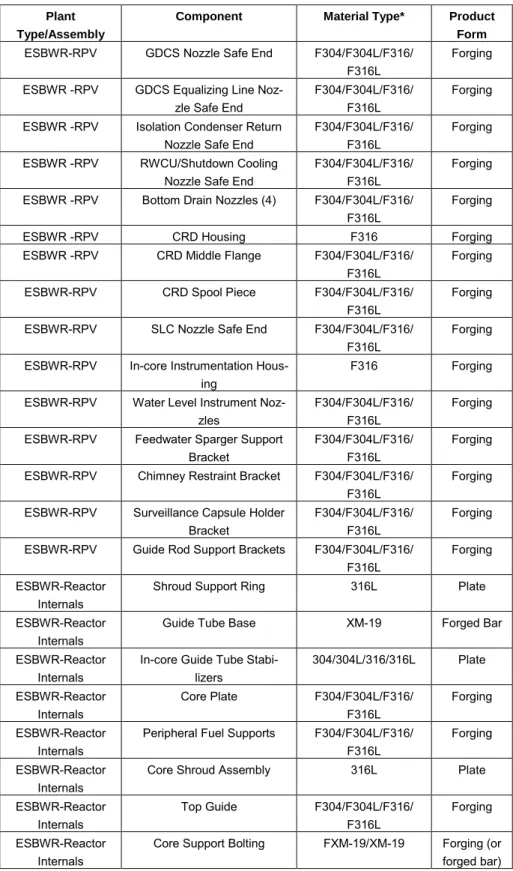
Table 3 Use of Stainless Steel Forgings and Plate in the ESBWR, from XGEN.11
Plant Type/Assembly
Component Material Type* Product
Form
ESBWR-RPV GDCS Nozzle Safe End F304/F304L/F316/ F316L
Forging ESBWR -RPV GDCS Equalizing Line
Noz-zle Safe End
F304/F304L/F316/ F316L
Forging ESBWR -RPV Isolation Condenser Return
Nozzle Safe End
F304/F304L/F316/ F316L
Forging ESBWR -RPV RWCU/Shutdown Cooling
Nozzle Safe End
F304/F304L/F316/ F316L
Forging ESBWR -RPV Bottom Drain Nozzles (4) F304/F304L/F316/
F316L
Forging
ESBWR -RPV CRD Housing F316 Forging
ESBWR -RPV CRD Middle Flange F304/F304L/F316/ F316L
Forging ESBWR-RPV CRD Spool Piece F304/F304L/F316/
F316L
Forging ESBWR-RPV SLC Nozzle Safe End F304/F304L/F316/
F316L
Forging ESBWR-RPV In-core Instrumentation
Hous-ing
F316 Forging
ESBWR-RPV Water Level Instrument Noz-zles
F304/F304L/F316/ F316L
Forging ESBWR-RPV Feedwater Sparger Support
Bracket
F304/F304L/F316/ F316L
Forging ESBWR-RPV Chimney Restraint Bracket F304/F304L/F316/
F316L
Forging ESBWR-RPV Surveillance Capsule Holder
Bracket
F304/F304L/F316/ F316L
Forging ESBWR-RPV Guide Rod Support Brackets F304/F304L/F316/
F316L
Forging ESBWR-Reactor
Internals
Shroud Support Ring 316L Plate
ESBWR-Reactor Internals
Guide Tube Base XM-19 Forged Bar
ESBWR-Reactor Internals
In-core Guide Tube Stabi-lizers 304/304L/316/316L Plate ESBWR-Reactor Internals Core Plate F304/F304L/F316/ F316L Forging ESBWR-Reactor Internals
Peripheral Fuel Supports F304/F304L/F316/ F316L
Forging ESBWR-Reactor
Internals
Core Shroud Assembly 316L Plate
ESBWR-Reactor Internals Top Guide F304/F304L/F316/ F316L Forging ESBWR-Reactor Internals
Core Support Bolting FXM-19/XM-19 Forging (or forged bar) *All 300 series stainless steel is 0.02% maximum carbon
**Isolation Condenser return line
†Pipe may also be 304/304L/316/316L extruded or drawn
Use of Stainless Steel Forgings and Plate in the ESBWR, from XGEN.11
Table 3 Continued Plant Type/Assembly
Component Material Type* Product
Form ESBWR-Reactor Internals Chimney Structure 304/304L/316 /316L Plate ESBWR-Reactor Internals
Chimney Head Rim and Cover
304/304L/316/316L Plate ESBWR-Reactor
Internals
Chimney Head Bolt Support Structure
304/304L/316/316L Plate ESBWR-Reactor
Internals
Steam Dryer Assembly 304/304L/316/316L Plate ESBWR-Reactor
Internals
Feedwater Thermal Sleeves F304/F304L/F316/ F316L
Forging ESBWR-Piping
Systems
Condensate** Lines, Fittings, and Valve Bodies
F304/F304L/F316/ F316L
Forging†
ESBWR-Piping Systems
GDCS Lines, Fittings, and Valve Bodies F304/F304L/F316/ F316L Forging† ESBWR-Piping Systems
RWCU Lines, Fittings, and Valve Bodies
F304/F304L/F316/ F316L
Forging†
*All 300 series stainless steel is 0.02% maximum carbon **Isolation Condenser return line
†
Pipe may also be 304/304L/316/316L extruded or drawn
Table 4 Use of Stainless Steel Forgings and Plate in the AP1000, from XGEN.11
Plant Type/Assembly
Component Material Type Product
Form
AP1000-RPV Primary Inlet/Outlet Safe Ends
F316L/F316LN Forging AP1000-RPV Direct Injection Nozzle
Safe Ends
F316L/F316LN Forging AP1000-RPV
Closure Head
CRDM Latch & Rod Travel Housings F304LN Forging AP1000-RPV Closure Head CRDM Adapter F304LN Forging AP1000-RPV Closure Head
CRDM Guide Funnel and Extension
F304LN Forging AP1000-RPV
Closure Head
Instrument Penetration Adapter and Housings
F304L/F304LN/F3 16L/F316LN
Forging AP1000-Reactor
Internals
Upper Support Welded Assembly 304/304L/304LN/ 304H Plate AP1000-Reactor Internals
Upper Guide Tube Flanges 304/304L/304LN/ 304H
Plate AP1000-Reactor
Internals
Upper Core Plate 304 Plate
AP1000-Reactor Internals
Core Shroud 304 Plate
AP1000-Reactor Internals
Upper Core Barrel 304 Plate
AP1000-Reactor Internals
Core Barrel Flange and Nozzles
F304 Forging
AP1000-Reactor Internals
Lower Core Barrel and Reinforcement Plate
304 Plate
AP1000-Reactor Internals
DVI Deflector F304/304L Forging AP1000-Reactor
Internals
Lower Core Support Plate F304H Forging AP1000-Reactor
Internals
Radial Supports 304 Plate
AP1000-Reactor Internals
Secondary Core Support Assembly
304 Plate
AP1000-Reactor Internals
Neutron Shield Panels and Spacer Blocks
304 Plate
AP1000-Reactor Internals
Vortex Suppression Plate 304 Plate AP1000-Reactor
Internals
Core Shroud 304 Plate
*Mostly forged pipe and fittings, but may also include some extruded pipe **NPS 6 inch (150 mm) nominal and greater
Use of Stainless Steel Forgings and Plate in the AP1000, from XGEN.11
Table 4 Continued Plant
Type/Assembly
Component Material Type Product
Form
AP1000-Reactor Internals
Core Shroud 304 Plate
AP1000-Reactor Internals
Upper Core Barrel 304 Plate
AP1000-Reactor Internals
Core Barrel Flange and Nozzles
F304 Forging
AP1000-Reactor Internals
Lower Core Barrel and Reinforcement Plate
304 Plate
AP1000-Reactor Internals
DVI Deflector F304/304L Forging AP1000-Reactor
Internals
Lower Core Support Plate F304H Forging AP1000-Reactor
Internals
Radial Supports 304 Plate
AP1000-Reactor Internals
Secondary Core Support Assembly
304 Plate
AP1000-Reactor Internals
Neutron Shield Panels and Spacer Blocks
304 Plate
AP1000-Reactor Internals
Vortex Suppression Plate 304 Plate AP1000-Primary
Piping**
Hot Leg and Cold Leg Piping and Branches
F304/304L/304LN / 316/316L/316LN
Forging* AP1000-Primary
Piping**
Surge Line Piping F304/304L/304LN / 316/316L/316LN
Forging* AP1000-Primary
Piping**
ADS Squib Valves and Piping Components F304/304L/304LN / 316/316L/316LN Forging* AP1000-Primary Piping**
Passive Core Cooling Heat Exchanger Outlet Piping
F304/304L/304LN / 316/316L/316LN
Forging* AP1000-Primary
Piping**
RHR Suction and Return Piping Components F304/304L/304LN / 316/316L/316LN Forging* AP1000-Primary Piping**
Core Makeup Tank Outlet Header F304/304L/304LN / 316/316L/316LN Forging* AP1000-Primary Piping**
DVI Header and Piping F304/304L/304LN / 316/316L/316LN
Forging* AP1000-Primary
Piping**
Accumulator Injection Header and Piping
F304/304L/304LN / 316/316L/316LN
Forging* *Mostly forged pipe and fittings, but may also include some extruded pipe
**NPS 6 inch (150 mm) nominal and greater
Use of Stainless Steel Forgings and Plate in the AP1000, from XGEN.11
Table 4 Continued Plant
Type/Assembly
Component Material Type Product
Form
AP1000-Primary Piping**
IRWST Header Piping Components F304/304L/304LN / 316/316L/316LN Forging* AP1000-Primary Piping**
ADS Header, Valves, and Piping F304/304L/304LN / 316/316L/316LN Forging* AP1000-Primary Piping**
Safety Relief Valves and Piping F304/304L/304LN / 316/316L/316LN Forging* AP1000-Primary Piping**
Passive Core Cooling Return Header F304/304L/304LN / 316/316L/316LN Forging* AP1000- Pressur-izer
Surge Nozzle Safe End F316LN Forging AP1000-
Pressur-izer
Safe Ends-Safety and ADS Valve Nozzles
F316LN Forging AP1000-
Pressur-izer
Heater Support Plates 304L Plate AP1000-SG
Channel Head
Primary Inlet and Outlet Safe Ends
F316LN Forging AP1000-SG
Channel Head
PXS PRHR Heat Ex-changer Return Nozzle
F316LN Forging AP1000-SG
Channel Head
CVS Return Nozzle Safe End
F316LN Forging AP1000-Core
Makup Tank
Inlet and Outlet Nozzle Safe Ends
F316 Forging
AP1000-Passive RHR Heat
Ex-changer
Tube Supports, Mounting Frame, etc.
304 Plate
AP1000-Passive RHR Heat
Ex-changer
Extended Flanges F304 Forging
AP1000-Passive RHR Heat
Ex-changer
Inlet and Outlet Nozzle Safe Ends
F316LN Forging
*Mostly forged pipe and fittings, but may also include some extruded pipe
**NPS 6 inch (150 mm) nominal and greater
Table 5 Use of Stainless Steel Forgings and Plate in the U.S. EPR, from XGEN.11
Plant Type/Assembly Component Material Type Product
Form
EPR-RPV Primary Inlet and Outlet Safe Ends
F316* Forging EPR-Closure Head CRDM Adapter Flanges F304* Forging EPR-Closure Head Instrument Adapter
Con-nector
F304* Forging EPR-Reactor Internals Upper Support Assembly 304* Plate EPR-Reactor Internals Upper Core Plate F304* Forging EPR-Reactor Internals CRGA Columns F304/304* Forging/Plate EPR-Reactor Internals Level Monitoring Probe
Columns
F304/304* Forging/Plate EPR-Reactor Internals Normal Column Flanges
and Brackets
304* Plate
EPR-Reactor Internals Guide Tube Support Plates 304* Plate EPR-Reactor Internals Instrument Guide Brackets 304* Plate EPR-Reactor Internals Heavy Reflector Slabs F304* Forging EPR-Reactor Internals Vertical Keys 304* Plate EPR-Reactor Internals Core Barrel Assembly
(flange, shells, outlet noz-zles)
F304* Forging
EPR-Reactor Internals Lower Support Plate F304* Forging EPR-Reactor Internals Heavy Reflector Positioning
Keys and Inserts
304* Plate
EPR-Reactor Internals Access Plugs F304* Forging EPR-Reactor Internals Flow Distribution Support
Columns
F304* Forging EPR-Reactor Internals Flow Distribution Plate F304* Forging
EPR-Primary Piping Hot Leg and Integral Branch Connections
F304* Forging EPR-Primary Piping Crossover Leg and Branch
Connections
F304* Forging EPR-Primary Piping Cold Leg and Integral
Branch Connections
F304* Forging EPR-Primary Piping Surge Line Pipe and Fittings F304* Forging EPR-Primary Piping Piping other than Main Loop
and Surge Line
304L/316LN Pipe EPR-Primary Piping Pipe Fittings other than
Main Loop and Surge Line
F304L/F316LN or WP304L/WP316 LN Forging or Fitting
EPR-RCPB Valves Bodies and Bonnets F304*/F304L/F3 04LN/F316*/F31 6L/F316LN
Forging
EPR-Primary Coolant Pump
Thermal Barrier Flange F304* Forging EPR-Pressurizer Nozzle Safe Ends F316* Forging EPR-Pressurizer Heater Support Plate 316L Plate *0.03% maximum carbon
Use of Stainless Steel Forgings and Plate in the U.S. EPR, from XGEN.11
Table 5 Continued
Plant Type/Assembly Component Material Type Product
Form
EPR-Pressurizer Spray Heads and Sleeves F316L or 316L Forging or Plate EPR-Pressurizer Heater Support Hardware
and Brackets
F316L or 316L Forging or Plate EPR-Pressurizer Surge Nozzle Debris Screen F316L or 316L Forging or
Plate EPR-Steam Generator
Channel Head
Primary Inlet and Outlet Nozzle Safe Ends
F316* Forging EPR-Steam Generator Upper Tube Bundle
Wrap-per and Roof
304L Plate
EPR-Steam Generator Feedwater Pipe, Fittings, Deflector Plate, Supports
316L/F316L Pipe/Plate/F orging *0.03% maximum carbon
Table 6 Use of Stainless Steel Forgings and Plate in the APR1400, from XGEN.11
Plant Type/Assembly Component Material Type Product
Form
APR1400-RPV DVI Nozzle Safe End F316LN Forging APR1400-Closure Head CEDM Motor Housing
Fittings
F347 Forging APR1400-Closure Head CEDM Guide Cone F304LN Forging APR1400-Reactor Internals Upper Guide Structure
Support Barrel Assem-bly
304 Plate
APR1400-Reactor Internals Upper Fuel Alignment Plate
304 Plate
APR1400-Reactor Internals Lift Rig Guide and Guide Lugs
304 Plate
APR1400-Reactor Internals Inner Barrel Assembly 304/F304 Plate/Forging APR1400-Reactor Internals Control Element
As-sembly Guide Tubes/Webs
304 Plate
APR1400-Reactor Internals Upper Core Barrel (flange, shell, nozzles)
304/F304 Plate/Forging APR1400-Reactor Internals Lower Core Barrel and
Flange
304/F304 Plate/Forging APR1400-Reactor Internals Snubber Lugs 304 or F304 Plate or
Forging APR1400-Reactor Internals Core Shroud Top Plate 304 Plate APR1400-Reactor Internals Core Shroud Panels,
Ribs, Ring, Braces
304 Plate
APR1400-Reactor Internals Core Shroud Bottom Plate
F304 Forging APR1400-Reactor Internals Lower Support
Struc-ture Beams and Plates
304 Plate
APR1400-Reactor Internals Instrument Nozzle Support Plate
304 Plate
APR1400-Primary Piping Surge Line Pipe and Fittings
347/F347/WP347 Pipe/Forging*/ Fittings APR1400-Primary Piping Shutdown Cooling Pipe
and Fittings
316/F316/WP316 Pipe/Forging*/ Fittings APR1400-Primary Piping Direct Vessel Injection
Line
304 or 316 and WP304 or
WP316
Pipe/Fittings
APR1400-Primary Piping Safety Relief Valve Body
F316LN Forging APR1400-Pressurizer Surge Nozzle Safe End F347 Forging APR1400-Pressurizer Spray Nozzle Safe End F316 or F347 Forging APR1400-Pressurizer SRV Nozzle Flanges F316 or F347 Forging APR1400-SG Channel
Head
Divider Plate 410S Plate
*Branch connection safe end
Use of Stainless Steel Forgings and Plate in the APR1400, from XGEN.11
Table 6 Continued.
Plant Type/Assembly Component Material Type Product
Form
APR1400-Steam Genera-tor Internals
Tube Supports (Egg crates and Bars)
409 Plate
APR1400-Steam Genera-tor Internals
Feedwater Flow Distri-bution Plate
405 Plate
APR1400-Primary Pump Seal Housing and Cov-er
Type 630 (17-4PH)
Forging *Branch connection safe end
Table 7 Use of Stainless Steel Forgings and Plate in the APWR, from XGEN.11
Plant Type/Assembly Component Material Type Product Form
APWR-RPV Primary Inlet and Outlet Safe Ends
F316* or F316LN
Forging APWR-RPV DVI Nozzle Safe End F316* or
F316LN
Forging APWR- Closure Head CRDM Housings F316* or
F316LN
Forging APWR- Closure Head In-Core Instrument
Nozzle Adapter Flange
F316* Forging APWR- Closure Head In-Core Instrument
Housings
F316* Forging APWR-Internals Upper Support Assembly 304/F304 Plate/Forging APWR-Internals Top Slotted Column
Flanges
304 Plate
APWR-Internals Upper Core Plate 304 or F304 Plate or Forging APWR-Internals Control Rod Guide
Plates
304 Plate
APWR-Internals Instrumentation Support Flanges and Brackets
304 Plate
APWR-Internals Mixing Devices 304 Plate
APWR-Internals CRDM Thermal Sleeve Guide Funnels
F304 Forging
APWR-Internals Neutron Reflector Ring Blocks
F304 Forging
APWR-Internals Upper Core Barrel (flange, shell, nozzles)
304/F304 Plate/Forging APWR-Internals Lower Core Barrel Shell 304 Plate APWR-Internals Head and Vessel
Align-ment Pins
F304 Forging
APWR-Internals Lower Core Support Plate
F304 Forging
APWR-Internals Radial Support Keys F304 Forging APWR-Internals Secondary Core Support
Columns
F304 Forging
APWR-Internals Diffuser Plate Support Columns
F304 Forging
APWR-Internals Upper and Lower Diffus-er Plates
304 Plate
APWR-Internals Base Plate 304 Plate
APWR-Primary Piping Main Loop Pipe and Fittings
F316* or F316LN
Forging APWR-Primary Piping Surge Line 316*/316L Pipe and Forged
Fittings APWR-Primary Piping RHR Suction Line 316*/316L Pipe and Forged
Fittings APWR-Primary Piping Safety Injection Line 316*/316L Pipe and Forged
Fittings *Carbon limited to 0.05% maximum
Use of Stainless Steel Forgings and Plate in the APWR, from XGEN.11
Ta-ble 7 Continued. Plant Type/Assembly
Component Material Type Product Form
APWR-Primary Piping Pressurizer Spray Line 316*/316L Pipe and Forged Fittings APWR-Primary Piping Safety Depressurization
Piping Components
316*/316L Pipe and Forged Fittings APWR-Primary Piping Depressurization and
Safety Valves F304*/F304L/ F304LN/ F316*/F316L/ F316LN Forging
APWR-Primary Piping Isolation Valves F304*/F304L/ F304LN/ F316*/F316L/ F316LN Forging APWR-Primary Pumps Thermal Barrier/Diffuser Flanges F304*/F304LN /F31*/ F316LN Forging APWR-Primary Pumps Main Flange F304*/F304LN /F316*/ F316LN Forging APWR-Primary Pumps Seal Housing F304*/F304LN /F316*/ F316LN Forging
APWR-Pressurizer Surge Nozzle Safe End F316* or F316LN
Forging APWR-Pressurizer Safe Ends-Safety and
Depressurization Valve Nozzles
F316* or F316LN
Forging
APWR-Pressurizer Spray Nozzle Safe End F316* or F316LN
Forging APWR-Pressurizer Spray Head F316* or
F316LN
Forging APWR-Pressurizer Internal Spray Piping F316* or
F316L
Forging APWR-SG Channel
Head
Primary Inlet and Outlet Safe Ends F316* or F316LN Forging APWR-Steam Gener-ator
Tube Support Plates 405 Plate *Carbon limited to 0.05% maximum
Figure 10
Region of abnormal grain growth (lower left) in uniaxial forged XM19.
Figure 11
Stringer of MnS plus NbC carbides in uniaxial forged XM19.
Technologically, the best case condition is achieved and expected of Ni-based and Fe-Ni based superalloys used in critical engineering applications. In many cases, Finite Element Modeling (FEM) is used to predict strains produced by each forging step and grain size refinement resulting from recrystallization. The FEM work itself is supported by data on; flow stresses of the metals being forged, temperature and strain to recrystallization; and forge strain rate effects. Similar technology could be applied to much simpler metals such as stainless steels to produce consistent bulk forgings, but the cost impact would be significant and if the specification environ-ment does not require microstructural uniformity, then there’s no motivation for vendors to adopt these methods. A critical factor in achieving uniform microstruc-tures is, in many cases, the ability to forge at lower temperamicrostruc-tures. Forging at lower temperatures does require higher press tonnages and hence returns to the original issue of vendor capability.
A good, practical example is the 310s stainless steel plate that was received in the partially recrystallized condition shown in Figure 1. The material clearly never received sufficient strain during hot working to recrystallize the dendrite grains and
the resulting microstructure consists of fine, nucleated-then-recrystallized, equiaxed grains surrounding the dendrite boundaries. The introduction of greater than 70% strain during hot working is typically required for full recrystallization of ingot structures. Since the objective of procuring this material was for testing, this micro-structure was unacceptable. Poor as-received micromicro-structures are a common occur-rence in plate materials, and so a repair forging and heat treatment was needed to make the material usable. The starting microstructure is compared to the repaired microstructure, as seen in Figure 12. In this example, the fix required a cold work-ing step to force deformation into the dendrite grain cores. Forgwork-ing at high, “recom-mended” temperatures would have concentrated plastic strain in the fine grained necklace structure, drive further recrystallization there, and left intact dendrite cores. The 1054°C forge step was low enough to ensure uniform dynamic recrystallization during forging.
So when we ask what factors could have influenced the quality of austenitic stainless steels used to construct nuclear power plants from the plant build period of 1960’s to 1970’s to present, the overwhelming factor was the upheaval in the global steel in-dustry that occurred between 1974 and 1986.2
A
B
Figure 12
A) As-received microstructure of ATI Allegheny Ludlum 310 stainless steel, heat 835342, piece 41044AA, lot 250651. B) Material re-processed using a 20% cold reduction by forging in thickness direction, followed by a 1054°C for 30 minute heat treatment then hot forged at 1054°C with isothermal dies at 1054°C to a 50% reduction followed by a 1065°C for 1 hour recrystalliza-tion anneal then water quenched.