Thesis paper, Computer Science
CDT307
Erik Thorstenson [19850808-1711] etn09004@student.mdh.se
February 21, 2013
Examiner: Sr. Lecturer Dag Nystr¨om Supervisor: Prof. Bj¨orn Lisper
Abstract
The hardware that computers consist of may for different reasons be difficult to monitor, the price may be high or the hardware itself may be unavailable. The most apparent reason though is the fact that hardware generally is not transparent, i.e. the hardware does not provide informa-tion on how a task is conducted, only its result. To provide a virtual en-vironment that enables simulation according to specific input parameters effectively solves many of the issues associated with hardware evaluation. Simulation has applications everywhere, not the least in computer science: From the low level of micro code all the way up to interpreting a high level implementation on top of a profound software stack. This thesis entails a virtual environment running a MIPS pipeline, although the simulator is implemented in the high level language C, it executes simulation at the fairly low level of assembler code. When provided with a user specified configuration file, the environment allows simulation of MIPS assembler programs, through the CPU, via interconnecting buses, ending at the level of virtual memory.
Acknowledgements
During this project I have been located in Shanghai, China. I received a scholar-ship to spend one semester at East China University of Science And Technology. I shortened the scholarship to 3 months to better suit my ongoing courses at M¨alardalen University and the period in which I had planned to do this project. Since I knew that guidance from my supervisor and colleagues back in Sweden would be limited I made sure to be prepared before leaving for Shanghai. I would like to thank the people who throughout February to April 2012 helped me with all of my conundrums. Thanks to this preparation, I have mostly man-aged with help from my Chinese Supervisor Fei Luo, whom I also would like to thank.
Contents
1 Introduction 1
1.1 Purpose . . . 1
1.2 Prospects and delimitations . . . 1
1.3 Problem formulation . . . 2
1.4 Roadmap . . . 3
2 Scientific background 4 2.1 Computer architectures . . . 4
2.2 RISC . . . 7
2.3 Simulation of computer architectures . . . 8
2.3.1 MIPS . . . 9 2.4 Existing simulators . . . 9 2.4.1 SPIM . . . 9 2.4.2 Simics . . . 10 2.4.3 SimpleScalar . . . 10 2.4.4 Gem5 . . . 10 3 Solution 12 3.1 Predefined MIPS pipeline simulator . . . 12
3.2 What needs to be solved . . . 14
3.2.1 System configuration interpreting . . . 14
3.2.2 Initialisation of system structures . . . 14
3.2.3 Parsing of the MIPS program . . . 14
3.2.4 Simulation and tracing . . . 14
3.2.5 Information management . . . 14
3.2.6 System tear down . . . 14
3.3 Verifying and interpreting user input . . . 14
3.3.1 The configuration file . . . 15
3.3.2 MIPS assembler code interpreting . . . 16
3.4 Memory hierarchies . . . 16
3.5 Calculating penalties and cost of communication . . . 18
3.6 Virtual memory . . . 19
3.7 The production of output . . . 20
3.7.1 Statistical information on memory structures . . . 20
3.7.2 Debug information . . . 21
3.7.3 CPU information per cycle . . . 21
4 Method 22 4.1 Software development methods . . . 22
4.1.1 Agile development . . . 22
4.1.2 Sequential development . . . 23
4.1.3 Conclusion . . . 24
4.2 Programming . . . 24
4.2.1 Predefined parts of the MMS . . . 25
5 Result 26
5.1 The application of a simulation . . . 26
5.2 Evaluation . . . 27
5.3 Future Work . . . 27
5.3.1 System functionality enhancements . . . 28
5.3.2 User interaction and experience enhancements . . . 29
6 Appendix 32 6.1 BNF Grammar . . . 32
1
Introduction
This project has been implemented at East China University of Science and Technology (ECUST) [3] in Shanghai, China, thanks to the scholarship Linnaeus-Palme [11]. Instead of choosing a pre-existing project from a company, MDH or ECUST I choose to define my own idea. The Idea as well as the result of this project is a simulator aimed at the MIPS [9, Chapter 4.1] [26] computer archi-tecture which from here on will be referred to as the MIPS Memory Simulator, or the three word abbreviation (MMS).
1.1
Purpose
Simulation of computer architectures is generally done in relation to research and development or education. Developing new CPUs or designing complete architectures is tedious work, simulation can be at great help. Simulators are frequently used in educational environments as complements to literature. The main motivation for developing the MMS is to gain a deeper understanding of how simulation works in general and computer architectures in specific. The MMS is in other words first and foremost a project that has been carried out with academic motivations rather than educational or professional. Other mo-tivations for the MMS are:
• The project is not connected to any commercial interests and may there-fore be freely used for educational purposes if found suitable. The MMS could be made available as an open source application allowing others to learn from it or make improvements
• The MMS could be applied as a tool to help understand the ways of computer architectures and e.g. present challenges in designing effective systems
• The project subject is closely related to the overall topic of the education it is meant to finalize
• The project subject is large enough to allow for future improvements and/or studies
1.2
Prospects and delimitations
The discrepancy between the original idea, which was formed during the autumn of 2011 and the specification that later on was approved as a suitable bachelor thesis, are fairly wide. During the phase of forming the idea, the main focus was the ability to simulate different types of computer architectures, and the possibility of an easy comparison between them. What represents the most pre-eminent alteration to the original idea is that only one architecture is simulated. An architecture for which a code base able to perform simulation already had been implemented by Linus K¨allberg on behalf of M¨alardalens University. The reason for this rather big change was mainly that the project proved too big in relation to the period of time during which it should be accomplished. The focus was in a sense moved from the execution of code to what happens when code is executed, the existing code base worked as a foundation for the MMS
to be built on. The idea was allowed to mature and ended up as figure 1 on page 12 describes. The details related to the figure will be discussed in chapter 3. Further delimitations where made to the original idea, most of which were decided upon during project planning. During its development the MMS did see a few revisions, mostly regarding which instructions to support, the system as a whole remained intact. The most important alterations to the MMS include:
The simulator
• will not handle peripheral devices
• will not handle interrupts
• will not implement instructions for floating point arithmetic
• will not implement certain instructions that may be compositions of other instructions, or may not be seen as important enough regarding evaluation of memory and CPU utilisation
1.3
Problem formulation
Simulation is an extensive subject, there most often exists a border where the simulation can end, the context to simulate has a scope in which the simula-tion should fit. The process of simulasimula-tion is often faced with the dilemma of choosing between speed and accuracy, it is therefore important to have a clear understanding of what needs to be simulated. The need for simulation appears when there exists a problem or a question to be answered in a context that is either not available or hard to come by. Apart from the academic motivations the MMS is meant to be a tool with applications in education and/or research. Considering the MMS as the solution, the problems could be identified as:
• The possibility to evaluate the level of utilisation a program has on the CPU and memories
• The possibility to examine many different virtual hardware configurations in a short amount of time, compared to evaluating real hardware
• The possibility to present an intuitive and less theoretic method of learn-ing for students in computer architecture, less theoretic compared to e.g. reading a book
• The possibility to analyse what a programs minimum demand for hard-ware is, many systems often run highly predictable and repetitive softhard-ware
• The possibility to create virtual models of computer components yet to exist. Rendering it possible to test, research and experiment with different configurations quick and easy
If looking through a more implementation specific viewpoint the MMS presents some questions worth mentioning:
• What information should be gathered during a simulation, i.e. what kind of diagnostic information should the simulator produce as output
• Should the simulation, apart from being as logically accurate as possible, strive to mimic the logical appearance as well. How should e.g. intercon-necting buses be realised, should the system rely on implied buses that are only taken into consideration whilst calculating communication costs or should buses be explicit structures in the simulator
• During the implementation, regarding distribution of time, which mea-sures should be taken in order to make future improvements and additions to the simulator easier
• There are subjects within the boundaries of the project that in their own suffices as thesis topics, e.g. input verification, compiler theory and data presentation. How should time be distributed amongst these important, though not central, parts of the simulator
1.4
Roadmap
This paper is structured more or less chronologically to reflect the progress of work as accurately as possible. Section 1 is meant to present a brief description on why the project was chosen. Further on it discusses prospects and delim-itations and the projects purpose. Section 2 is dedicated to introducing the reader to the concept of computer architectures in general, simulation of com-puter architectures and too present some existing simulators. Section 3 begins by presenting the parts of the MMS that has not been developed in relation to this project but still presents important functionality. More importantly it discusses what has been developed during this project, it defines what problems needs solving and thereafter presents what solutions that have been applied. Section 4 discusses Software engineering methods and concludes in what way the MMS has been developed. It also discusses how programming has been carried out, e.g. what languages that has been used and how programmatic and implementation specific problems have been approached. Section 5 explains the application of a simulation and what information is needed for a simulation to be able to run. It also focuses on future work and which additions would present the most gain in functionality to the MMS.
2
Scientific background
Simulation is the operation of imitating a real world process [2], the motivation may be to get a result, study a process or both. Simulation is used in many fields such as testing, evaluation, optimization, safety, entertainment, prognostication, education and indescribably many more areas. Simulation can be applied to just about any subject, not the least computer science. Alan Turing [12, Chapter 4.2] is said to be the father of computer science, the Turing machine [12, Chapter 4.2] which he introduced in 1936 is said to be the inception of the modern computer. Alan Turing also invented the Universal Turing Machine [12, Chapter 4.6] which is interesting since it can simulate any arbitrary Turing Machine. Simulation is conducted at different levels of detail depending on the purpose. The most detailed simulators are accurate at the level of single CPU cycles, others are rather to be considered as interpreters where all that matters is the output or result. There exists a trade off between speed and accuracy, it is a staggering thought to imagine a simulator that operates at the deepest level of accuracy with preserved speed and swiftness. But speed and accuracy rarely go hand in hand unless the complexity of a process to simulate is lower than the capacity of the resources. In the same area as simulation is the concept of emulation [20], it is sometimes hard to tell the difference between the two and different definitions exists. Emulation is about the imitation of a system within another system acting like a host, whereas simulation rather would act as the host system.
2.1
Computer architectures
The architecture of a computer is the relation between its hardware parts. An early and significant architecture is the design of logical components made by John Von Neumann [6] in 1945 which led to the Stored Program Computer [6, pages 282 - 289]. The stored program computer is an actuality today and is in a wider perspective referenced to as the Von Neumann Architecture [6, pages 282 - 289], its core idea is the uniform handling of instructions and data in memories. The more modern Harvard Architecture [25] dictates separate storage for instructions and data, many of today’s computer configurations are hybrids of the two: The primary memory is shared but the low level cache memories store instructions and data separately.
The main parts of a computers architecture are the CPU, the memories and the communication buses. The CPU reads instructions from memory, de-codes them and performs appropriate operations on either registers or memory locations, it then stores or places the result in a designated register and/or eventually writes the result back to memory. A processor has access to several registers which are destined for different purposes, some should strictly be used for passing arguments to subroutines, others should be used for storing tempo-rary data or alike. MIPS e.g. has access to 32 registers able to contain 32 bits of data each. The register of a CPU is often accessible and read or written in a single CPU cycle which is incredibly fast. Registers are kept small in order to maintain the fast access, maintaining a small physical distance between the information and where it is needed also plays a part. The kind of memory used in a CPU register is expensive, generally the further away from the CPU the cheaper and larger is the memory used.
sev-eral phases, to begin with each instruction needs to be loaded into the CPU. Thereafter several stages or phases usually follow, the flow of an instruction is completely dependent on the architecture at hand. Generally an instruction needs to be decoded so the system can interpret it. Instructions sometimes con-tains arithmetic expressions that needs to be evaluated, if a result is produced it needs to be stored to a register and/or memory. Thanks to the fact that in-structions only exist in one stage at a time a CPU may allow several inin-structions to execute simultaneously, called pipelining. At the same time as an instruction is being decoded an other is being loaded from memory and a third is using the ALU1 to evaluate an arithmetic expression, and so forth. Pipelining can dramatically increase the performance of a computer system in general because:
• The capacity of a CPU is better utilized since more of its logical parts are used more frequently
• Without Pipelining a CPU will most often need a longer clock cycle since more logic needs to be applied to an instruction in each cycle
• When a pipeline is fully operating it finishes an instructions as well as starts executing a new one in each cycle, this fact in relation to the shorter cycle time of a non pipelined system is perhaps to most important benefit
Pipelined CPUs generally reach a higher level of complexity than non pipelined CPUs, this is however motivated due to the increase in performance.
Memories of a system are, depending on the situation, organized in hierar-chies to be able to utilize the principle of locality [9, Chapter 5.1, 5.2]: Data that recently has been referenced or data close to it has a certain degree of probability to be referenced again. Therefore a computer is able to make use of cache memories which store subsets of information from larger memories that exist further away from the CPU. Cache memories becomes smaller and faster the closer they are to the CPU in relation to the memory hierarchy they are part of. Cache memories contains blocks of information, a block contains and represents data that has recently been referenced as well as surrounding data which may or may not be referenced. Since cache memories only reflect parts of other larger memories there will be conflicts on what blocks that should be contained in them. Least Recently Used (LRU) [9, Chapter 5.3] is an algorithm commonly used with associative memories [9, Chapter 5.3] in which a block of data can be placed anywhere within its designated set of indices. The purpose of LRU is to keep track of which block in a set of blocks has been unused for the longest period of time and therefore should be evicted when a new block has to fit in the same group of blocks. There exists a vast number replacement schemes of which many are simple: First In First Out, Round Robin and Ran-dom Replacement. Cache memories are also used to store address translations and are in that context called Translation Look aside Buffers (TLB) [9, Chapter 5.4]. TLBs are useful when working with virtual memory [9, Chapter 5.4] which requires that virtual addresses are translated into physical locations before a memory can be accessed. The mappings between virtual and physical addresses are kept in page tables. TLBs act as cache memories for the page tables which
1An ALU is a hardware component able to perform arithmetic operations and is a central part of any CPU
generally are stored in a computers main memory making it expensive to access them.
Memory accesses can be expensive, although accessing and finding an address translation in a TLB is lightning fast it may still correspond to several clock cycles where the CPU has to stall. A reference to main memory may correspond to millions or billions of clock cycles. In order to minimize the number of times that TLBs needs to be referenced, or atleast minimize the cost of accessing them, a system may address its closest cache memories using completely or partly virtual addresses. In the general case a CPU needs to refer a TLB to trade its virtual address to a physical location, this can however be avoided. Addresses are generally divided into three parts: Index; Tag; Block offset. The Index represents which block or cache line that an address belongs to; The Block Offset represents what data within a block that an address refers to; The tag is a part of the actual data stored in memory and is used to determine if some data is the correct data or some other data that maps to the same index and offset. The following combinations represents how a system may address a cache memory:
• Physically Indexed, Physically Tagged (PIPT) is the case where a virtual address always needs to be translated before a memory location can be read. Although this scheme is fail safe it is slow. every access that the CPU does to its memory needs to be proceeded by an address lookup. If the translation for the address is not currently cached then off course main memory needs to be referenced
• Virtually Indexed, Virtually Tagged (VIVT) is the case where the CPU can access a cache memory based solely on the virtual address. Data can be retrieved without consulting a TLB or in worst case a page table in main memory. This approach opens for a very fast execution but does however suffer from aliasing problems where several different virtual ad-dresses point to the same physical address. It also suffers from coherency problems, where the same virtual address points to different physical lo-cations. Both of which are related to the fact that different processes use the same virtual addresses
• Virtually Indexed, Physically Tagged caches uses the virtual address for indexing, and the physical address for the tag. It does not suffer from aliasing or coherency problems, and it has lower latency compared to PIPT. As the index is virtual the cache line might be looked up in parallel with the tag lookup in the TLB. When the possible cache line is ready for comparing the TLB lookup has taken place without any extra cost in time
• Physically Indexed, Virtually Tagged (PIVT) is merely a symbolic case and would be useless. There is no point in the index being virtual whilst the tag is physical since the index is used before the tag
Virtual memory is used to let processes view and access memory as contin-uous memory exclusively available to them. The fact that a computer in reality often contains a widely diversified and sometimes fragmented memory system is not something that processes ever notices. Each process that executes is as-signed its own virtual memory space. It allows processes to operate in a sealed
off environment not having to mind other processes, or allowing other processes to access their data for that matter. The operating system is responsible for mapping and distributing physical memory to which ever processes that needs it.
Different parts of an architecture communicate through buses [9, Chapter 6.5] which are sub-systems that transfers data, the capacity of a bus is deter-mined by its width in bits and speed in Hz. The rhythm of a computer is more or less determined by the bus that connects the CPU to main memory and peripheral devices, it sets a ground speed of which other buses and the CPU derives their own speed. The possibility to access several memories through sev-eral buses is a deviation from the Von Neumann architecture that for a gensev-eral purpose computer is indispensable.
2.2
RISC
Reduced Instruction Set Computing (RISC) [8] is the opposite of Complex In-struction Set Computing (CISC) [8], the most apparent distinction between them is what is implied by their names. The instructions of a RISC architec-ture are generally simple, optimized and regular, the instructions in CISC are allowed to be complex. CISC could be compared to, or viewed as RISC with in-struction compositions: If a CISC inin-struction is broken down then many of the pieces can be identified as RISC instructions. The main goal of CISC is to finish a task in as few assembler instructions as possible which is why the instructions tend to be complex, CISC can also be allowed to alter memory banks directly which also reduces the amount of instructions. RISC on the other hand employs the Load/Store architecture where memory needs to be accessed by load and store operations: all values for an operation need to be loaded from memory and be present in registers, the result needs to be stored back to memory after the operation has been carried out. This can be exemplified by translating a regular statement from the language of C such as:
1 a = a ∗ b
Into assembler code for RISC and CISC, listing 1 shows a perceivably compli-cated way of doing it whereas listing 2 can seem quick and easy to grasp.
Listing 1: Pseudo code for altering a memory location using RISC 1 // Load t h e v a l u e a t t h e s p e c i f i e d memory l o c a t i o n i n t o
t h e r e g i s t e r r 1
2 LOAD ( r 1 ) , ( Memory l o c a t i o n one )
3 // Load t h e v a l u e a t t h e s p e c i f i e d memory l o c a t i o n i n t o t h e r e g i s t e r r 2
4 LOAD ( r 2 ) , ( Memory l o c a t i o n two )
5 //Add t h e v a l u e s and p l a c e t h e r e s u l t i n r 1 6 ADD ( r 1 ) , ( r 1 ) , ( r 2 )
7 // S t o r e t h e v a l u e i n r e g i s t e r r 1 a t t h e s p e c i f i e d memory l o c a t i o n
8 STORE ( r 1 ) , ( Memory l o c a t i o n one )
1 ADD ( Memory l o c a t i o n one ) , ( Memory l o c a t i o n two )
One of the advantages with CISC is its low usage of memory since a lot can be accomplished with just a few instructions. The price of memory is no longer a problem whereupon this advantage has lost its edge. CISC does however keep a stronghold over desktop computers thanks to the x86-architecture [27]. RISC architectures are though more customary in the field of embedded systems, tablets and smart phones with popular architectures such as ARM [24] and MIPS [26]. Some of the advantages with RISC are:
• CISC takes advantage of features intended to facilitate manual assembly coding. As compilers have become more sophisticated they are capable of optimisations far more complex than what a human generally can achieve. This fact renders RISC a better approach because of the more dedicated instructions.
• When working with RISC the hardware needs less logical units and compo-nents since the instructions are more explicit and includes less operations • The simplicity and regularity of RISC instructions makes overlapping of
processor stages, called pipelining, easier to achieve
• RISC instructions are simpler and can therefore be conducted in less time which enables a shorter cycle time
• Since RISC operates on registers the amount of time spent on memory accesses is reduced, something that proved valuable as processors reached new speeds making memory accesses more expensive
There are also many advantages with CISC, obviously related to the fact that the instructions can perform more operations. The effects of Complex instructions may be:
• The possibility to operate on a memory location directly, without loading it to a register explicitly
• Moving or copying large memory sections
• The possibility to write the content of several registers to memory at once
• The possibility to execute operations atomically, e.g. a test-and-set oper-ation1
• The possibility of advanced and floating point arithmetic in single instruc-tions
2.3
Simulation of computer architectures
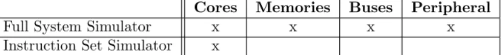
When simulating computer architectures you generally speak of two branches; Full System Simulators (FSS) [10] aim to implement an entire system in depth, making it possible to run full software stacks; On the opposite side there are Instruction Set Simulators (ISS) [21] which primarily aim to simulate CPUs.
1A Test And Set operation is dependent on the possibility to access and read a memory location without the possibility of it being interrupted in the process
Cores Memories Buses Peripheral
Full System Simulator x x x x
Instruction Set Simulator x
Table 1: Comparison of simulated components between FSS and ISS
Depending on the context in which a simulation is carried out, a simulator can often roughly be categorized as being driven by functional or timing related motivations. Regarding the execution, a functional simulator can limit its scope to the keyword what, whereas a timing oriented simulator would need the vital addition of the keyword when. A concept that is proven to have an expansive measure of applicability are Cycle Accurate Simulators (CAS). Although gen-erally more difficult to realize, CASs are in comparison with other less accurate simulators more versatile though sometimes not as fast. CASs work on a rela-tively low level where simulation is conducted on a cycle-by-cycle basis, a CAS satisfies many needs and must amongst other demands ensure that memory ac-cesses, branch predictions1, pipeline stalls2 and context switching3occurs when
they are suppose to. If a real world execution makes use of α cycles then a CAS should use α cycles as well in order to be accurate.
2.3.1 MIPS
MIPS (Microprocessor without Interlocked Pipeline Stages) is a reduced in-struction set computer (RISC) inin-struction set architecture (ISA) which was first developed during the 1980s, it has seen many revisions and additions and is a widely used ISA. MIPS main usage has historically been in embedded systems, it is also commonly used in educational environments in conjunction with the book Computer Organization and Design – The Hardware/Software Interface by David A. Patterson and John L. Hennessy.
2.4
Existing simulators
2.4.1 SPIM
SPIM [9, Appendix B.9] is a cross platform simulator with educational mo-tivations, it employs a graphic interface and has the option to operate cycle accurately. Alike the MMS it accepts MIPS assembler instructions, unlike the MMS SPIM offers static memory architectures. The memory management of SPIM is limited to toggling whether or not to use e.g. caching of address trans-lations, instructions and data. Whilst using SPIM it is possible to set flags to inform SPIM on what memory structures to use:
• Data cache consisting of 512 lines, each 32 bytes
• Instruction cache consisting of 512 lines, each 32 bytes
• Translation look aside buffer (TLB) consisting of 64 lines, each 20 bits
1Branch Prediction is the act of a CPU predicting the flow o a program
2Pipeline Stalls occurs when there is a hold-up, such as a memory access, and execution of a process needs to be halted
There are a couple of observations and clarifications to be made: Turning either the instruction or data cache off does not imply a situation where the system needs to access the system bus to fetch information from main memory, it solely means that memory accesses will not stall the CPU; Since the TLBs lines have the predetermined length of 20 bits there are 12 bits left for the virtual memory page size, leaving it fixed at 4 KB; Turning the TLB off will render the caches working with physical addresses.
2.4.2 Simics
Although there are binaries available for educational use, Simics [13] is first and foremost a commercially oriented simulator, mostly used to run software on hardware that has yet to leave the drawing board. Simics is a full system, cycle accurate simulator that allows entire software stacks, such as operating systems, to run in virtual environments.
Operating in a deterministic manner, Simics guarantees that from the same state, the same path of execution will always be chosen. This property makes way for some of Simics most powerful features:
• Execution from a checkpoint may be started over and over
• The smallest functional parts of Simics are single machine instructions, with the use of checkpoints it is possible to single step through them both backwards and forwards.
• Checkpoints are saved to file making it possible to evaluate different con-figurations over time
2.4.3 SimpleScalar
SimpleScalar [14] is distributed under an open source licence and is free of charge to non-commercial and academic users. It simulates the Alpha, PISA, ARM, and x86 instruction sets on most unix or windows-based platforms. The SimpleScalar software is used to build modelling applications for performance analysis of real programs. It is also capable of detailed micro-architectural modelling and hardware-software co-verification. The SimpleScalar software is adaptable to fit different needs, it can be configured as a fast result-oriented functional simulator. Or it may be configured as a dynamically scheduled pro-cessor model that supports non-blocking caches1, speculative execution2, and
branch prediction.
2.4.4 Gem5
Gem5 [4] is a simulator distributed under an open source licence and designed for use within research. Gem5 is a full system simulator which support multiple ISAs and CPUs as well configurable memory hierarchies and the possibility to
1Upon a cache miss, a non-blocking cache may handle additional calls to it whilst waiting for data from above in the hierarchy
2Speculative Execution may be utilized when a CPU is waiting. To possibly save time it may execute instructions that are not certain to be needed. If the result turns out to not be needed it is ignored, otherwise time has been saved
simulate clusters1both in terms of cores and separate systems. Gem5 simulates
the Alpha, ARM, SPARC, MIPS, POWERPC and x86 ISAs and has full system simulation capabilities for all of them. Many simulators, including the MMS, are implemented using a non-object orientated2 language. Gem5 has however
been implemented using object orientated principles which contributes to its modularity. Gem5 is marketed as interchangeable, modular and highly config-urable. Systems may be set up in a variety of ways and may be combined into larger systems and so forth.
1A Cluster is a collection of entities that are collaborating. A cluster may consist of multiple cores within a system, or e.g. multiple systems collaborating via a network or alike
2Object Orientation implies the use of objects which usually are instances of classes, objects encapsulates data fields and methods
3
Solution
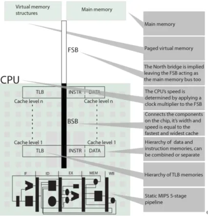
Apart from details and the specific problems of and solutions to different parts, the MMS in overall strives to mimic the properties of hardware. This implies that even though more effective variants of some solution exists the MMS might favour a slower, less effective version in order to keep the simulation closer to the reality. This behaviour is exemplified and becomes somewhat apparent minding Figure 1 which, although refined, represents the original design from which the implementation is derived. Figure 1 was the last part to be done in the project planning phase, it is representative for what the MMS is capable of abstractly.
Figure 1: How the system is constructed to function, both logically and seman-tically
3.1
Predefined MIPS pipeline simulator
MMS is short for MIPS Memory Simulator, the ”Memory” part is what rep-resents the core of what has been accomplished in this project. The ”MIPS” part is represented by the MIPS 5-stage Pipeline Simulator (MPS) that was developed by Linus K¨allberg on behalf of M¨alardalen University as an educa-tional tool. The MPS is implemented in C and reflects the core instructions of the 32-bit implementation of MIPS and a five stage pipeline. The MPS
en-sures the syntactical correctness of each MIPS program by the use of a lexical analyser generated with Flex [1, Chapter 3.5] [15] and a parser generated with Bison [1, Chapter 4.9] [16] , more on this in section 3.3.2. The MPS was chosen to be included in the project due to lack of time, to implement a pipeline as well as a dynamic memory system would not have been suitable in accordance with the thesis syllabus [7]. The MPS has been adapted to fit with the ad-ditions that this project carries and is basically the foundation on which the MMS has been built, they reflect different parts of a unified system. The MPS is capable of executing MIPS assembler instructions, it progresses instructions through the five pipeline stages in a cycle-by-cycle manner. The MPS further-more has knowledge of the memories closest to it and is therefore able to read and write whatever data the instructions it is executing demands. The MPS has no knowledge about the design of the system beyond its closest memories. If only minding functionality regarding simulation a distinction can be made between the MPS and the MMS at the point of accessing a memory:
The MIPS Pipeline Simulator is neither more or less than a pipeline able to execute MIPS assembler instructions, when a new instruction is to be read or when an instruction asks to access memory the MPS knows where to start; The other part of the MMS is neither more or less than a memory hierarchy with a paged virtual memory layer surrounding it, the hierarchy may be read from or written to on demand.
The basic measurement of time in the MMS is the cycles of the pipeline in the MPS, each cycle corresponds to a period of time and is a direct function of the CPUs speed in Hz. The pipeline is basically implemented as five functions representing the five pipeline stages:
1. The Instruction Fetch stage the address in the Program Counter (PC) register is read and the corresponding memory location is accessed. In reality all 32-bit MIPS instructions make use of 32 bits, the MMS does however let instructions use more memory in order to keep things simple and to save time during the development. The 32 bits are however im-portant to mind when considering memory utilisation so the MMS writes the 4 byte pointers too its simulated memory instead of the instructions themselves. The Instruction Fetch stage is also where the pipeline checks for and predicts branching
2. The Instruction Decode stage is in reality vital since it decodes and makes the instructions readable for the processor, the stage is however somewhat symbolic in the MPS as well as the MMS since instructions are not stored in their encoded format
3. The Execution stage is where logical operations are conducted, i.e. address calculations and arithmetic operations
4. The Memory stage is where data is stored from a register to memory or loaded from a memory to a register
5. The Write Back stage is where information from either a memory load or the result from the Execution stage are stored in the register file
3.2
What needs to be solved
In order to keep implementation, documentation and planning of the project at a structured level, the MMS is divided into sub-problems each representing a part of the simulator with specific properties and problems.
3.2.1 System configuration interpreting
The simulator needs a configuration to simulate, since the user of the simulator needs to provide the configuration there has to exist an easy-to-use yet powerful interface for supplying it.
3.2.2 Initialisation of system structures
The system will need to be initialised in a specific order since certain structures may depend on other to already have been initiated: The MIPS program to simulate cannot e.g. be written to memory before a memory exists.
3.2.3 Parsing of the MIPS program
Although programs run in the MMS and/or the MPS might be error-prone during their execution, measures need to be taken to make sure that there are no lexical or syntactical errors. Also, the source program needs to be interpreted and written to a memory structure in order for the MMS to run it.
3.2.4 Simulation and tracing
The simulator needs to simulate the execution in a functionally accurate way to allow for tracing, in the scope of this project, the simulator will not provide a runtime transparency, diagnostic information will only be considered after execution has finished.
3.2.5 Information management
Some general diagnostic structure or the structures that the simulator consists of, e.g. memories or page tables, will need to hold information on how the simulation has utilized each part of the simulator. The information should then be available for analysis and presented in an informative and interesting way.
3.2.6 System tear down
Before the simulator shuts down, allocated structures and resources need to be returned to the operating system. This process can be conducted as with any standard C program, Some Heap debugging mechanism will be used to ensure that the simulator is correctly released.
3.3
Verifying and interpreting user input
The user of the MMS needs to specify the system to simulate and the program to be run in it. The system is specified by providing a configuration file and within should be a name of the file containing the program to be run in the system.
3.3.1 The configuration file
The MMS is highly configurable, the specifics for configuring i.e. a memory can be seen in listing 4 on page 17. The configuration file needs to be called ”config” and have the file extension ”cfg”, the MMS will then read the file from beginning to end searching for tags that indicate that a system structure will be specified. Each tag is handled uniquely in its own function specialized on initializing that structure, after a structure has been initialized the MMS will continue to search for tags until the end of the configuration file appears. The file may contain comments by starting a line with ’#’.
The configuration file needs to be structured in a certain manner, the infor-mation it contains is however relatively free for the user to specify however he or she wants. There are no limitations or rules on how to configure the system, there are no controls to check if i.e. the size of a memory is evenly dividable by the size of its blocks. The user must in other words exercise common sense in order to achieve a functional environment.
The shell of the configuration file is structured with meta-tags, each tag tells the input interpreter what to do with the information associated with the tag. Listing 3 explains which tags exist and in what order they should appear.
Listing 3: The tags used to specify the systems structures in the configuration file 1 #w e t h e r o r n o t t h e s y s t e m s h o u l d p r i n t d e b u g i n f o r m a t i o n d u r i n g e x e c u t i o n 2 <debugmode> 3 </debugmode> 4 5 #A d a t a o r i n s t r u c t i o n memory 6 <mem> 7 </mem> 8 9 #A t r a n s l a t i o n l o o k a s i d e b u f f e r 10 <t l b > 11 </ t l b > 12 13 #The f r o n t s i d e b u s 14 <bus> 15 </bus> 16 17 #A p r o c e s s c o n t r o l b l o c k 18 <pcb> 19 <p a g e t a b l e > 20 </ p a g e t a b l e > 21 </pcb>
There is no limit to the amount of mem, tlb or pcb tags that can be specified, though the system is not prepared for any more then one Process Control Block. The configuration file needs to satisfy a few basic requirements in order for the system to function:
• At least one memory designed to hold instructions
• At least one memory designed to hold address translations
• The specifics of the Front Side Bus
• Which program to simulate
• The total and page size of the virtual memory
The complete rules and possible layouts of the configuration file are specified by the BNF grammar in section 6.
3.3.2 MIPS assembler code interpreting
The correctness of the MIPS program to be run in a simulation and the inter-preting of it is highly dependent on the use of a lexical analyser and a parser.
Flex [1, Chapter 3.5] [15] is a tool used to generate lexical analysers which are used to tokenise an input program. It is commonly used together with the parser generator Bison [1, Chapter 4.9] [16] which takes Context Free Grammars (CFG) as input and generates Look Ahead Left to Right (LALR) parsers as output. A program can be validated by letting a parser work its way through the tokens that a lexical analyser provides.
The use of Flex and Bison in the MMS is a feature that has been adapted from the MPS that was created by Linus K¨allberg. The parsing related mecha-nisms have been slightly modified by implementing support for two instructions:
• Jump Register, the execution of instructions will continue at the address specified by a register
• Jump And Link, the execution will continue at a specified address and the return address will be automatically stored in a return register
The MMS is structured to provide the parsing related mechanisms with pointers to the simulated memory and a file descriptor to the MIPS program file to parse. The parser will then go through the lexically analyzed input, writing identifiers to memory and creating a list of instructions which are written to memory after the parsing process. The MIPS assembler program is written to memory in its assembler form, in a real situation the instructions would be handled in their binary format.
3.4
Memory hierarchies
The MMS provides two or three different memory hierarchies depending on how they are viewed, memories containing data and instructions can be separate but will inevitably be united at some point since they will always share the mem-ory at the top of the hierarchy, the hierarchy of Translation Look aside Buffers (TLB) relies on the page table and is therefore separate. Apart from a few dif-ferences in the read and write functions for memories, all memories are identical. They use the same programmatic structures and the same algorithms, what de-termines the function of a memory is partially its location in the hierarchy and which bus it is connected to. But also a variable which tells if it can contain data, instructions or address translations. The CPU has knowledge of where to
find the memory or memories closest to it, thereafter, provided a hierarchy has been specified, memories are accessed in a recursive manner. Traversing the hi-erarchy means that memories read from the memory above and then writes the information to itself rendering the information readable to the memory below.
Memories are specified in the configuration file and need to be structured as listing 4 shows.
Listing 4: An example of the specification of a memory in the configuration file, The MMS supports 4 kind of memories: TLBs; Data memories; instruction memories; Combined memories that can store both instructions and data. The field Memory Type is used to set what kind of information is to be held in a memory 1 <mem> 2 #s i z e i n b y t e s 3 32768 4 #b l o c k s i z e i n b y t e s 5 32 6 #a s s o c i a t i v i t y 7 1024 8 #Memory t y p e 9 0 10 #r e p l a c e m e n t p o l i c y 11 1 12 #c a s l a t e n c y 13 3 14 #ns from p r e v i o u s s t r u c t u r e 15 2 16 </mem>
In listing 4 each row starting with a ’#’ contains meta-information about the row directly beneath it. Each row not starting with ’#’ contains data that will be decisive for the memory’s design:
• The ”Size in bytes” is the total size of the memory and may vary in powers of 2
• The ”Block size in bytes” is the size of the memory’s rows and may vary in powers of 2
• The ”Associativity” is the number of blocks that should be contained in each set of blocks, may vary in powers of 2
• The ”Memory type” determines what kind of information the memory may contain: Data; Instructions; Data and instructions; Address translations
• The ”Replacement policy” determines which method will be used to evict a block when information needs to be written to set of blocks that is full
• The ”Cas latency” tells the amount of time that a memory needs to provide a row of data from the moment it is told to provide it
• The ”NS from previous structure” tells the amount of time it takes for the memory to send or receive data to or from the memory below in the hierarchy, or the CPU if it is the last memory
The smallest accessible parts of a memory are single bytes, the specification of a memory needs to specify how many bytes that each memory block should consist of. A byte is the smallest part that the CPU can access, memories must however access entire blocks, blocks are entities that apart from the actual data they can hold contains meta-information: A block can be valid for reading or writing; it can be initiated which means that it has been written; It can be dirty which means that it has been altered and needs to be written to the memories above in the hierarchy before it can be altered again; It has zero or one of the four LRU-bits set. First in First Out (FIFO) which is self explanatory is however used in the memory at the top of the hierarchy, this is due to the fact that no secondary storage exists whereupon no evictions will occur and the cost of LRU is not motivated.
Along the line of endorsing spatial and temporal locality [9, Chapter 5.1, 5.2] is associative memories, the MMS handles associativity at both extremes, specifying a memory to be 1-way associative renders it direct mapped, making LRU obsolete. Specifying the associativity to be equal to the total memory size divided by the size of the blocks renders the memory fully associative. Since the MMS holds four LRU-bits for each block it can handle 4-way associative memories in a deterministic manner, if the associativity is more than four the LRU replacement scheme will be approximate.
3.5
Calculating penalties and cost of communication
The calculation of execution times is to be seen as one of the main features of the MMS. The detailed information on time spent in memories is also what represents the core of the output of the MMS.
Calculating time spent reading or writing memories is not a general op-eration that can be properly conducted in a general manner. Manufacturers have their own specifications, patents and conventions, memories are, unlike e.g. Instruction Set Architectures, often possible to exchange without changing any other part of a system. This fact motivates the choice to let the simula-tion of memory access times be fully flexible and not based on manufacturers specifications, though it is possible to enter parameters to as closely as possi-ble resempossi-ble a specific memory module. The MMS is not simulating the logic within a memory which would be more complicated, instead the configuration file should specify a latency for each memory. The latency is the delay time between the moment a memory is told to access a particular memory column and the moment the data from the given location is available. The following pseudo code shows the algorithm used to calculate the time spent on an access.
Listing 5: Algorithm for calculating amount of time spent accessing a memory 1 // from t h e p r e v mem t o t h i s mem and back
2 Communications c o s t = Nano s e c o n d s t o p r e v i o u s memory ∗ 2 ;
4 //The t i m e i t t a k e s f o r t h i s memory t o p r o v i d e t h e b l o c k t o be read o r w r i t t e n
5 Cas l a t e n c y = The t i m e needed f o r t h e memory t o p r o v i d e a row o f d a t a
6
7 //The number o f c y c l e s needed t o s e n d t h e d a t a o v e r t h e bus
8 Number o f c y c l e s t o t r a n s f e r t h e d a t a = ( Number o f b y t e s t o s e n d ) / ( Width o f t h e bus ∗ The number o f times t h e bus can s e n d d a t a p e r
c y c l e ) ; 9
10 //The t i m e t h e bus n e e d s t o p e r f o r m one C y c l e 11 Nano s e c o n d s p e r c y c l e= 1000000 / t h e s p e e d o f
t h e bus i n MHz; 12
13 //The t i m e s p e n t on s e n d i n g d a t a o v e r t h e bus 14 Time Spent on bus = Number o f c y c l e s t o t r a n s f e r
d a t a ∗ nano s e c o n d s p e r c y c l e ) ; 15
16 t o t a l t i m e s p e n t = c o m m u n i c a t i o n s c o s t + Cas l a t e n c y + Time s p e n t on bus ;
Except for the latency of memories, it is important to mind the cost of com-munication over buses, in the MMS each memory specified knows the time it takes to reach the previous memory, this allows for simulation of the physical distances between components. The configuration file needs to specify the prop-erties of the Front Side Bus (FSB) [9, chapter 6.5] from which the cycles per second of the CPU and Back Side Bus (BSB) [9, chapter 6.5] are calculated. Listing 6: An example on how the FSB can be specified in the configuration file 1 <bus> 2 #mhz 3 600 4 #w i d t h i n b i t s 5 32 6 #c l o c k m u l t i p l i e r 7 8 8 #t r a n s f e r s p e r c y c l e 9 1 10 </bus>
Besides the latency to the structure beneath a memory, each memory knows which bus it is connected to. Buses are not explicit structures in the MMS which may be implied by figure 1, they are merely numbers applied to the calculation according to listing 5.
3.6
Virtual memory
The MMS provides a paged virtual memory layer which needs to be specified in the configuration file, the virtual address space is limited to 232 bytes and the
page size can vary in powers of 2. The system does not support but is somewhat prepared for context switching whereupon each Process Control Block (PCB) has its own virtual address space.
Listing 7: An example of the specification of the virtual memory in the config-uration file
1 <pcb>
2 #name o f f i l e c o n t a i n i n g MIPS program 3 program . s 4 <p a g e t a b l e > 5 #p a g e s i z e i n b y t e s 6 4096 7 #s t a c k s i z e i n b y t e s 8 16384 9 </ p a g e t a b l e > 10 <\pcb>
Accessing memories in the MMS should be proceeded by an address lookup which renders a physical address to a valid memory location. The address lookup itself can take different turns: Either the lookup is a success, meaning that there existed a translation somewhere in the hierarchy of Translation Look aside Buffers (TLB); Or the lookup ended without a result and the system needs to refer the page table, once again this can take different turns: Either a mapping exists in the page table and the result can be written to the TLB hierarchy; Or the page is not mapped which renders a page fault. Page faults in the MMS are merely symbolic since secondary storage does not exist. In the case of a page fault the MMS will create a mapping making it possible to work with the page, however, if the page fault occurred due to a memory access and not an address lookup the MMS will shut down since that would imply that secondary storage would exist.
3.7
The production of output
The MMS produces different types of output, all with different motives. The original output of the MPS has been preserved giving detailed information on each CPU cycle, the MMS carries detailed information on memory utilisation as well as extensive debug printouts during a simulation.
3.7.1 Statistical information on memory structures
Associated with each memory is a structure capable of storing diagnostic in-formation. During simulation the MMS will continually make notes on reads, writes, misses, hits, evictions and expenditure of time for each memory struc-ture. When the simulation is finished the MMS will go through the diagnostics, making relevant calculations and writing the information to file. The name of the output file is a composition of the current date and time and the file extension is ”opt”.
Listing 8: Information that has been gathered during a simulation and is pre-sented in the output file.
1 Memory ID : 4
2 ID o f memory above : 5
3 Memory type : T r a n s l a t i o n Look a s i d e B u f f e r 4 Replacement P o l i c y : L e a s t R e c e n t l y Used 5 A s s o c i a t i v i t y : 4 6 Number o f b l o c k s : 16 7 B l o c k S i z e 16 8 Nano s e c o n d s i n memory 28600 9 READS: H i t s : 1 0 9 , M i s s e s 32 10 WRITES : H i t s : 0 , M i s s e s 0 11 E v i c t i o n s 9 3.7.2 Debug information
Although mostly a tool during the development of the MMS the user may choose to include debug printouts by specifying so in the configuration file. The print-outs appear in the console and tells what happens when and in which memory. It is possible to trace every access and the sometimes fairly complex patterns that are the product of associative memories arranged in hierarchies.
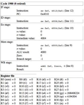
3.7.3 CPU information per cycle
The product of the MPS is a file reporting the state of the CPU after each cycle, this includes what data is contained in each register as well as what instruction is contained in each pipeline stage. The file is organized using HTML [17] and therefore offers a graphical experience.
At the top of figure 2 the 5 pipeline stages are shown, section 3, sub-section 3.1 describes the basic functionality of each stage. At the bottom of the figure are the contents of the register file, section 2 discusses register files briefly.
Figure 2: The look of the cycle-by-cycle information that is the output of the MPS
4
Method
This section is meant to discuss how a software such as the MMS can be devel-oped but more importantly how the MMS has been develdevel-oped. The software development method is laid out and concluded and the major programming conventions are explained.
4.1
Software development methods
When developing software there are numerous techniques to consider in order to keep work focused and effective, although many of the problems related to soft-ware development mainly occurs whilst collaborating in teams, working alone also demands for structure and consistency. Software development methods are roughly divided in two branches: the agile [19] [5] and the sequential [23].
4.1.1 Agile development
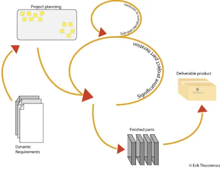
Agile Development (AD) endorses change and adaptation during the develop-ment, the project plan is alive and can even be allowed to take shape during a project. These properties are more or less bi-products of the cornerstone in Agile development: A project shall not rely on a single person or software part, the project shall be structured to allow for pieces and persons to be exchanged or removed. A suitable analogy could be a puzzle where any piece can be fitted at any time, the outcome of the puzzle will still be the same. The development
is in one way or another progressed through cycles depending on the level of agility, a cycle may represent one or several tasks within the project, or it may represent a period of time.
Figure 3: The iterative behaviour of agile development
The MMS has benefited from Agile ideas, work has been progressed through weekly meetings, also the work has been divided into sub problems that has been allowed to evolve and progress side by side, in the case of difficulties, focus has been put elsewhere until suitable solutions or ideas has been found. Many advantages of Agile development will though be more advantageous the more people that are included, to a limit. A one man project will e.g. not benefit as much as a multi person project would from the puzzle analogy, one person can only put down one piece at a time. Projects with fewer people will tend to avoid some of the problems associated with AD, too many people may render poor structure or the need for unjustified small puzzle pieces, to continue the analogy. Also, the more people involved, the higher will the requirements be on the overall organisation and planning. Since the MMS has been developed in a one man project, there has existed some limitations to the degree of agility possible to use, though there has throughout the project existed a strive to endorse AD.
4.1.2 Sequential development
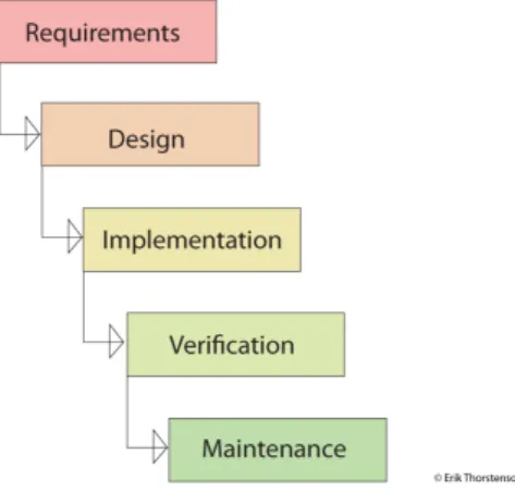
Sequential Development (SD) is said to be synonymous, or in a matter sprung from the Waterfall model where progress flows through the different phases of a project.
Figure 4: The main phases and flow through a project using the Waterfall model
property of SD that makes it stand out from Agile Development techniques is the difficulties that often occur in the case of problem or when having to redo some part. SD is not solely sequential, it may also be incremental, imagining a skyscraper it is obvious that construction can not start in mid air, it must be constructed from the bottom and up and it might be difficult to exchange pieces that is not on the very top. The MMS has not been developed with any SD ideas in mind, though it might be difficult to avoid some of the core ideas in single person projects. SD favours structure and regularity, as opposed to Agile Development a project can only exist in one stage at a time, something that in a sense is inevitable for one man projects.
4.1.3 Conclusion
The MMS has throughout its development been seen as a collection of dif-ferent systems: A Parser; A memory hierarchy; A virtual memory system; A Pipeline simulator; An information management system. These systems has been constructed at different times, sometimes in conjunction with each other, some times in completely different contexts. The point being that the MMS is a product of agility, it consists of different pieces that operate and function on their own but equally well fit together like a puzzle. Apart from agility, the MMS has benefited from Sequential Development mostly because it is a one man project, if more people would have been involved the project would probably have adapted an even more agile coarse of action.
4.2
Programming
The MMS has been programmed in C [22], a general purpose programming language which was developed during the early 1970s. C is one of the most widely spread languages of all time and is despite its age still very popular. The MMS does not make use of any third party Application Programming Interfaces, though it has been developed in conjunction with and is dependent on code generated by Flex and Bison which is covered in section 3.
4.2.1 Predefined parts of the MMS
Some parts of the MMS, such as the MIPS pipeline and parser was not originally programmed or generated in relation to this project, although these structures have been modified and adapted in a number of ways, they were to begin with alien and the majority of time spent on these structures have been spent in order to understand them. New parsers have had to be generated whereupon the grammar that defines the MIPS instruction set have been studied deep enough to allow for changes without introducing bugs. The pipeline have been thoroughly studied, mostly through debugging to understand the flow of operations, but also semantically in order to understand coding conventions and other properties that vary depending on the developer.
4.2.2 The defining of new structures
Most of the functionality in the MMS has been constructed during this project, the predefined parts appear at the ends of the simulation, the predefined pipeline being the deepest part and the generated parser lying on top. In between is where the majority of the developing within this project has taken place. Many of the structures, such as Page tables, memories, the virtual memory layer and process control blocks have been developed with a data centric approach. To begin with, a data structure is created, e.g. a memory, the structures interface is then allowed to grow and take shape in conjunction with the structure itself and the requirements that is put on it. Other parts such as the diagnostic infor-mation management, though operating on e.g. memories, have been developed as interfaces where the data is not as centric: A requirement is identified and satisfied through the interface, algorithms and data are applied afterwards. The operation of interpreting input data which is used to set up the environment to simulate is made possible through a mark-up behaviour. Inspiration has been taken from other mark-up languages such as HTML [17] and XML [18], this topic is discussed in section 3.
5
Result
The MMS is the outcome and product of this project, it presents a virtual envi-ronment for assembler code diagnosis. It accepts a configuration file and a MIPS assembler program as input and produces diagnostic information as output. The MMS is a system in which it is possible to study the effects a certain program has on a system configuration. In order for the MMS to be executed it needs to be placed in the same folder as a configuration file and a MIPS assembler program. After execution it will place a file containing diagnostic information in the same folder. This section focuses on what is actually outputted from a simulation as well as what additions could be made to the MMS in the future.
5.1
The application of a simulation
Amongst other things the MMS set out to be a scientific tool, this section will show how the MMS could be used, though this example will be at a fairly ob-vious level. The MIPS program to be simulated consists of 64 consecutive store operations which addresses 16 virtual memory locations 4 times in ascending order. By looking at the total amount of cycles used and the time spent waiting accessing memories it is possible to view the effects of changes made to i.e. a cache. The listings below presents the results of different simulations with focus on the cache memory storing data closest to the processor.
Listing 9: This configuration is not very effective in combination with the pro-gram simulated. There is no utilisation of spatial or temporal locality since there is too much data for the memory to handle. The memory is too small so the memory above in the hierarchy often needs to be referenced for reads and writes. This configuration needs 85990 CPU cycles to execute the program 1 A s s o c i a t i v i t y : 1 2 Number o f b l o c k s : 2 3 B l o c k S i z e 4 4 NS i n memory 26586 5 READS: H i t s : 0 , M i s s e s 62 6 WRITES : H i t s : 6 4 , M i s s e s 0
Listing 10: This configuration is more effective, the memory has enough room to gain from spatial locality whereupon other memories in the hierarchy does not need referencing as often. This configuration needs 44219 CPU cycles to execute the program
1 A s s o c i a t i v i t y : 1 2 Number o f b l o c k s : 16 3 B l o c k S i z e 4 4 NS i n memory 20256 5 READS: H i t s : 3 2 , M i s s e s 0 6 WRITES : H i t s : 6 4 , M i s s e s 0
Listing 11: This configuration is an example of the price you have to pay when a memory is over dimensioned. Even though this memory is capable of handling a lot more data and has the possibility of utilizing a lot more of spatial and
temporal locality it is the slowest configuration. The problem is the size of the blocks, every time the memory needs to read or write something to the levels above, it does so in chunks of 32 bytes which puts a lot of stress on the interconnecting buses. This configuration needs 126840 CPU cycles to execute the program. 1 A s s o c i a t i v i t y : 4 2 Number o f b l o c k s : 4 3 B l o c k S i z e 32 4 NS i n memory 20256 5 READS: H i t s : 3 2 , M i s s e s 0 6 WRITES : H i t s : 6 4 , M i s s e s 0
The time spent in the cache memory is the same for listing 10 and 11 which implies that a possible bottleneck or improvement is to found or done in another memory, bus or in the CPU. Minding the educational aspects of the MMS, finding such a bottleneck could present a challenge for students trying to understand how memory hierarchies function.
5.2
Evaluation
The MMS is capable of producing debug printouts which tells what happens when and in which structure, thanks to this the correctness of the MMS has continuously been evaluated during its development. Towards the end of devel-opment the MMS has been further evaluated using more subtle methods: E.g. a debugger to single step a complete simulation; Or making sure that the result of a simulated MIPS program is correct. The MMS has not seen any criticism from its possible users which most likely would bring light on how the MMS should interact with them, especially in what way to present the results of a simulation.
5.3
Future Work
The MMS operates in a field with practically unlimited possibilities for improve-ment and additions, mostly due to the never ending developimprove-ment of computer architectures but also due to the immense amount of existing and legacy archi-tectures. Although the possibility to simulate several instruction set architec-tures would have a large impact on the amount of possible users that the MMS could be of interest to, the MMS should first be subject to changes and additions that improve on the functionality that is needed within the context in which it operates. The MMS is primarily advocated by academic reasons but should also satisfy eventual scientific and/or educational demands, both of which calls for a reality-based and adaptable system. The MMS is a functioning simulator which offers both a connection to the reality with respect to MIPS, and flexibil-ity minding the possibilities of specifying the system through the configuration file. There however exists a countless number of additions, improvements and alterations to be made to the MMS, both in terms of system functionality and user experience.
5.3.1 System functionality enhancements
Much of the functionality that would contribute the most to the MMS is depen-dant or in some way related to making the MMS multi threaded1 [9]. A com-puter consists of several parts which may operate on their own which enables different work to happen simultaneously. The perceived realism of a simulator can benefit from operating in a multi threaded environment. Simulation can more closely resemble the reality where different components often have their own resources which are only available to them. The MMS only uses one thread in a single process whereupon the simulation visually is quite different from the reality. Operations that could and sometimes should take place at the same time executes sequentially, this is most apparent during memory accesses when the general CPU is able to perform context switches in order to let other processes execute.
Below is a general list of possible additions to the MMS of which many are related to the use of multiple threads. Others are dependant on other resources to be realized.
• The possibility to handle multiple processes and the ability to perform context switches between them. The addition of such functionality would not only further employ the use of virtual memory since more processes equals more virtual memory spaces. But it also allows for simulation more closely related to reality since many real-world systems executes more than one process
• Computers consists of several logical units, each operating atomically whereupon each could be represented by a thread. In the MMS this could entail instruction pre-fetching2 and/or the use of simultaneous memory
accesses and address look ups. Functionality that allows a system to ac-cess memory before an address translation exists is dependent on that one or more memories use virtual indexes (VIPT) and/or tags (VIVT) which is discussed in section 2.1, Computer Architectures on page 4
• Simulation of a scheduler in a multi process environment would allow for accurate context switching
• If simulating computation heavy programs or tasks, the use of multiple threads may carry a real world speed up of the simulation
• When the pipeline stalls due to memory accesses it will not do so in a proper manner. Since the MMS executes in one thread the pipeline will freeze until the memory access is complete. This is problematic since it deviates from the otherwise cycle accurate behaviour of the MMS. How-ever, since memories calculate the amount of time that has been spent accessing them, the CPU can calculate how many cycles that correspond to each access
• The possibility to Address memories with Virtual indices and tags
1A multi threaded program is a program consisting of several instruction streams 2Instruction pre-fetching is the act of a CPU loading instructions that are likely to be needed to its cache memories. The CPU may do so in lack of other things to do, it saves it the time from accessing main memory at a more critical point
5.3.2 User interaction and experience enhancements
The general user of the MMS needs to provide a complete system configuration as well as a MIPS assembler program. Both of which are fairly complex things that require a general understanding of how computers function at a low level. The MMS does not provide any guidelines or visual help on how a system should be configured, neither does the MMS analyse a users configuration: It is possible to design a system that will not function properly. The errors that would appear in such a case would not be unlike those that would appear in a real system that has been put together inappropriately. An obvious enhancement to the MMS would be a filter in which the system configuration could be analysed, errors could be detected and the user could even be given tips on how to improve on the configuration. Such functionality would not be unlike that of the validation of the MIPS assembler program which is syntactically and lexically verified when loaded into the MMS. The MMS might also gain from offering a more visual experience, especially during simulation but also after simulation when presenting results. A richer visual experience would probably have its largest application in an educational environment where it could serve a pedagogical and entertaining purpose. Each memory could be visualised showing how data is transferred and stored, buses connecting memories could show when data is transferred and so forth. After simulation graphs and other visual media could give an easier way of conveying diagnostic data.